1
TEMPERATUTE
CONTROLLER
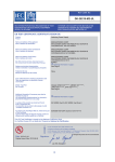
USER MANUAL
(KN303)
1
2
3 4
POWER
AC100~240V 50~60Hz
DC100~200V
5
FAN
OUT
6
7
8
ALARM
OUT
Pb
9 10 11 12 13
TRIP
OUT
FAULT
OUT
!
KN303
AUTO
MAN
MODE
T.MAX
TEST
CH 1
CH 2
CH 3
Pt100Ω
Pt100Ω
Pt100Ω
DC4~20mA RS-485
+
- T/X+ T/X-
16 17 18 19 20 21 22 23 24 25 26 27 28
Neuron Tech
CONTENTS
● Caution for Safety
---------------------
2
● KN 303 TEMPERATURE CONTROLLER --------
4
1. Specifications ------------------------
4
2. External Dimension and Panel Cutting Size ----
5
3. Connection Diagram --------------------
6
4. Features -----------------------------
7
5. Output Operating Diagram ----------------
7
6. Name of Each Part ----------------------
8
7. Operation and Setting -------------------
8
8. Example of Wring ----------------------
10
-1-
Caution for Safety
Caution for safety, aims at securing safety of user and preventing accident
or danger in advance by using it safely ,so read and follow it well.
Caution matters are divided into ‘warning’ and ‘caution’ whose meanings
are as follows
Violating instruction may cause serious damage or
death
Violating instruction may cause injury product
damage or material loss.
WARNING
CAUTION
WARNING
1.power
1) use it within rated voltage in order to protect equipment and prevent and
prevent trouble.
2) ln order to prevent electric shock and equipment damage when installing
equipment check wiring after finishing wiring and than input power.
3) use standard wiring and terminal for connecting power .this can cause
electric shock and fire.
2.caution for operation
1) lf abnormality of this equipment is related to serious accident, it is
recommended to install protection device in addition.
2) Do not use this equipment in the gas (This is not explosion-proof structure).
If this equipment is exposed to gas do not operate power switch and
so on but operate ane it when it is sage after venting the space.
3) Do not use in the place with chemical materials, There is danger of electric
leakage and electric shock.
4) Do not touch or loosen terminal when there is applied lt can cause electric
shock or mal -operation.
5) Do not touch the product when there is water around or when body is wet.
There is danger of electric shock.
6) Do not install the equipment in the place where children can touch the
equipment.
3. Caution for wiring and maintenance
1) Perform wiring for this equipment exactly into relevant number as show in
the instruction manual or terminal instruction. (Tighten terminal bolt firmly)
mal-wiring can cause equipment damage, mal- operation of fire .
2) Perform repair or assembling after turning off external power switch and
interrupting external circuit power. It can cause electric shock or trouble.
3) Never disassemble reform or repair equipment lt cause electric shock fire
product damage mal-operation or trouble.
-2-
4) Replace sensor after turning off power by all means. Lt can cause electric
shock.
Fire product damage mal-operation or trouble.
5) The components of this equipment have life period and include year -passing
components There is 1 year of guarantee period from purchasing date.
However. Trouble due to customer mistake and natural disaster is excluded.
CAUTION
1.caution for attachment and wiring
1) Fix the equipment firmly with the fixing device (included during shipment
below and above the equipment when attaching equipment.
2) lf there is severe induction noise in the power ,it is recommended to us
insulation transformer and noise removal circuit.
3) Twisted wiring of power line is effective for noise
4) lf water enters receive checking by all means.
5) Use lead wire which has low resistance is non-combustible.
6) Use output and input signal lines by separation them by all means. Use
shield wire for input signal wire and be away from load or high voltage.
7) Use sensor of non-grounding type.
2.Caution for handling
1) when operation output relay frequently by connecting load without
allowance in rating, relay life can be shorter rating so use it by adding relay
to outside. *Electric life of relay --About 100.000 times (under rated load)
2) Make each setting exactly and check abnormality in input and output,
3) lf sensor is single or short it is displayed “---”.
turn off voltage by all means when replacing sensor at this time .
It can cause trouble and mal -operation
4) Do not drop this product nor give shock this product. It can cause trouble
or mal-operation
5) Do not wipe the product with organic
solvent lt can cause damage in appearance .
6) Avoid use in the following condition.
: ln the place where surrounding temperature and humidity exceed the
temperature and humidity scope in usage condition.
: ln the place exposed to combustible gas or corrosive gas.
: ln the place where there is much oil water steam iron or salt.
: ln the place which is not waterproof structure exposed to outside water
or rain.
: ln the place directly exposed to direct sunshine.
: ln the place where freezing phenomenon takes due to severe
change of temperature and humidity.
-3-
KN303 DIGITAL TEMPERATURE CONTROLLER
Free voltage
(AC100~240V 50~60Hz,DC 100~300V )
3 sensor input(Pt100Ω)
Operation setting function for each channel(run/stop)
caution:”stop”seleced channel is not displayed.
Program type function
(Setting value)
Temp, max storage function for each channel
Data storage function
Fan auto / manual function
Test function for each input channel
Channels scanning
SCAN : ch1-2-3 scanning( 2~9 sec)
AUTO :automatic hottest scanning
MAN :manual function
Scan time setting function(2~10 sec)
Outputs delay time setting function
Fan ( 0.1~6.0 sec)
Alarm, Trip ( 0.5~10.0 sec)
1
2
POWER
3 4
AC100~240V 50~60Hz
DC100~200V
5
FAN
OUT
6
7
8
ALARM
OUT
9 10 11 12 13
TRIP
OUT
FAULT
OUT
!
KN303
AUTO
MODE
MAN
T.MAX
TEST
CH 1
CH 2
CH 3
Pt100Ω
Pt100Ω
Pt100Ω
DC4~20mA RS-485
+
- T/X+ T/X-
16 17 18 19 20 21 22 23 24 25 26 27 28
1.Specification
DIMENSION
115(W)X90.5(H)X72(D)mm
INPUT MEASURING CYCLE
100m SEC
ACCURACY
INPUT
+/- 0.5 ℃( Full Scale)
3 INPUT Pt100 Ω- 3WIRE(DIN IEC 751)
AMBIENT TEMPERATURE & HUMIDITY
OPERATION (-20 TO 60 ℃
MEASURING RANGE
- 50~250 ℃
1℃
TEMPERATURE INDICATION
/ 10 TO 90% RH)
OUTPUT CONTACTS CAPACITY
TRIP, ALARM , FAN, FAULT
RELAY CONTACT
AC 250V 5A(Resistance Load)
DC 30V 5A(Resistance Load)
ANALOG OUTPUT
DC 4~20mA (RANGE:0~200℃) Load Resistance Max 600Ω
(INPUT/OUTPUT ISOLATION)
COMMUNICATION
SERIAL RS-485 MODBUS RTU (OPTION: RS-232)
(INPUT/OUTPUT ISOLATION)
DATA STORAGE
10 YEARS
POWER SUPPLY
FREE VOLTAGE
AC 100V TO 240V 50~60Hz,DC 100~300V
POWER
7 VA
CONSUMPTION
DIELECTRIC STRENGTH
AC 2000V FOR 1MIN
INSULATION
DC 500V 100M ohm MINIMUM
RESISTANCE
WEIGHT
750g
-4-
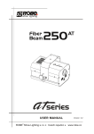
2.External Dimension and Mounting
◎ External Dimension
단위 :mm
115mm
72mm
96mm
1
2
POWER
3 4
AC100~240V 50~60Hz
DC100~200V
5
FAN
OUT
6
7
8
ALARM
OUT
9 10 11 12 13
TRIP
OUT
FAULT
OUT
!
KN303
90.5mm
90.5mm
AUTO
MAN
MODE
T.MAX
TEST
CH 1
CH 2
CH 3
Pt100Ω
Pt100Ω
Pt100Ω
(En50022)
MOUNTING
FOR DIN RAIL
DC4~20mA RS-485
+
+
-
- T/X+ T/X-
16 17 18 19 20 21 22 23 24 25 26 27 28
96mm
72mm
9mm
115mm
104mm
70.5mm
-5-
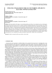
3.Connection Diagram
◎ Connection Diagram
1
2
3 4
POWER
AC100~240V 50~60Hz
DC100~200V
5
6
7
8
ALARM
OUT
FAN
OUT
9 10 11 12 13
TRIP
OUT
FAULT
OUT
!
CH1
Pt100Ω
CH2
CH3
Pt100Ω
Pt100Ω
DC4~20mA RS-485
+
- T/X+ T/X-
16 17 18 19 20 21 22 23 24 25 26 27 28
NOTE: When the unit is powered the fault relay 12-13 closed
and it opens again in case of fault condition
-6-
4.Features
Power input is free voltage (AC 100~240V,DC 100~300V) and it is stably
operated even at bad condition such as outside power change,surge etc
Temperature of transformer is measured and displayed and
alarm output (alarm, trip) and fan is controlled according to
temperature.
Temp max function -lt is possible to check the highest
temperature of transformer during operation up to now.
Data storage function memorizes T .MAX value and each control
temperature setting values.(Semieternal) T.MAX value is stored
even after turning power it is reset during operation.
Each setting value is also stored after turning off power unless
setting value is changed during operation.
Fan out function -lt is possible to control outside fan by
comparing fan on and fan off setting values and measured
temperature.
5.Output Operating Diagram
OUTPUT
SPECIFICATIONS(△:setting temp)
ALARM,TRIP
ALARM,TRIP ON
FAN OUT
FAN OFF
FAN ON
-7-
6. N ame of Each Part
(1)AUTO MODE
DISPLAY LED
(18)TEMP&SETTING DISPLAY
(2)MAN MODE
DISPLAY LED
(17)TRIP OUTPUT
DISPLAY LED
(3)Temp. Max
DISPLAY LED
(16)ALARM OUTPUT
DISPLAY LED
(4)FAN MANUAL OUTPUT
DISPLAY LED
AUTO
(15)FAN AUTO OUTPUT
DISPLAY LED
MAN
T.MAX
(5)PROGRAM MODE
DISPLAY LED
MODE
TEST
(14)FAULT OUTPUT
DISPLAY LED
(6)T.MAX CHECK SWITCH
(13)CHANNEL DISPLAY
(7)RESET SWITCH
(12)MODE/TEST SWITCH
(8)FAN MANUL ON/OFF SWITCH
(11)UP SWITCH
(9)PROGRAM MODE/SETTING SWITCH
(10)DOWN SWITCH
7. Operating and Setting
(1)AUTO : Control device automatically displays the highest
temperature channel
(2)MAN :Channel temperature manual reading through cursor keys
(3)T.MAX: Monitoring unit shows the highest temperature recorded
FUNCTIONS
by the sensor and the last reset
(4)FAN : FAN is automatically controlled by fan on and fan off
setting value
(16)ALARM:When the measurement temperature is over ALARM
setting value, ALARM ON
(17)TRIP :When the measurement temperature is over TRIP
setting value, TRIP ON
(8)T.MAX : T.MAX value check key(SCAN,AUTO,MAN mode only)
(9)RESET: RESET(In T.MAX MODE)->The current T.MAX
value delete and record again
(“RESET” key 3 seconds pressing)
OPERATION
(8)FAN MAN: FAN operation the button which the ON/OFF
KEYS
operation with a manual operation.
(9)PRG/ENT:PROGRAM MODE(“PRG/ENT”key 3 seconds pressing)
Program setting function key
(10)DOWN: When Program setting value change DOWN.
(11)UP
: When Program setting value change UP.
(12)MODE/TEST: DISPLAY MODE(SCAN,AUTO,MAN) change key
TEST MODE key
("MODE/TEST” key 3 seconds pressing)
-8-
Setting manual
After power supply
The display shows the measurement temperature
KN303
AUTO
MAN
MODE
T.MAX
TEST
PRG
Pressing ENT key 3 seconds
PRG ON PRG ON led turns on
" Fan on " Setting display
PRG
ENT
" FAN ON " Setting value changes
PRG
ENT
Save the changed setting value
" Fan oFf " Setting display
PRG
ENT
" FAN OFF " Setting value changes
PRG
ENT
Save the changed setting value
" ALarm on Setting” display
PRG
ENT
" ALARM ON " Setting value changes
PRG
ENT
Save the changed setting value
" Trip on Setting” display
PRG
ENT
" TRIP ON " Setting value changes
PRG
ENT
Save the changed setting value
“Com Id " Communication ID setting display
PRG
ENT
" COM ID " Setting ID value changes
PRG
ENT
Save the changed setting value
Return to first display
PRG
* Anywhere in the program by pressing ENT key 3 seconds
or key operation is not longer than 30 seconds
in the measurement mode is changed.
* Measurement mode
PRG ON PRG ON led turns off
-9-
8.Example of Wiring
◎ In case of Phase
16 A
POWER SOURCE
(USER SUPPLY)
1¢ AC 100~240V
50~60Hz
R
1
T
1
2
3
AC100~240V
50~60Hz
DC100~300V
17 B
CH 1
18 BA
19
MCCB
T1
R1
FAN
OUT
20
3
21
4
22
5
TO CUSTOMER
ALARM
OUT
23
6
25
8
TO CUSTOMER
MC
TRIP
OUT
26
9
27
10
28
11
TO CUSTOMER FAULT
OUT
M FAN MOTOR
CH 2
BA
B
CH 3
B24
7
MC
B
+
DC4~20mA
TO CUSTOMER
COMMUNICATION
TO CUSTOMER
T/X+
T/X-
RS-485
12
13
◎ In case of Three Phase
16 A
POWER SOURCE
(USER SUPPLY)
R S T
1
1
2 3
2
AC100~240V
50~60Hz
DC100~300V
17 B
18 BA
CH 1
19
MCCB
20
R1 S1 T1
FAN
OUT
3
4
5
TO CUSTOMER
ALARM
OUT
6
7
8
TO CUSTOMER
TRIP
OUT
10.
MC
MC
U V
9
21
22
23
B
BA
B
B24
25
26
27
28
CH 2
CH 3
+
DC4~20mA
TO CUSTOMER
COMMUNICATION
TO CUSTOMER
T/X+
T/X-
RS-485
11
W
TO CUSTOMER
M FAN MOTOR
FAULT
OUT
12
13
- 10 -
Neuron Tech
A 303 ,875-1Maesonggosaek-Ro, Gwonseon-Gu,
Suwon-City, Gyeonggi-Do, Korea, 441-230
TEL : +82-31-227-4504 / FAX : +82-31-298-1962
www.neurontech.kr