1
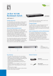
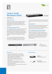
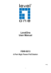
FSW-1650 FSW-2450 User Manual 16/24 10/100 Rackmount Switch V3.0..0906 COPYRIGHT & TRADEMARKS Specifications are subject to change without notice. LevelOne is a registered trademark of Digital Data Communications Asia Co., Ltd. Other brands and product names are trademarks or registered trademarks of their respective holders. No part of the specifications may be reproduced in any form or by any means or used to make any derivative such as translation, transformation, or adaptation without permission from Digital Data Communications Asia Co., Ltd. All rights reserved. FCC STATEMENT The Switch has been tested and found to comply with the limits for a class A digital device, pursuant to part 15 of the FCC Rules. These limits are designed to provide reasonable protection against harmful interference in a residential installation. This equipment generates, uses and can radiate radio frequency energy and, if not installed and used in accordance with the instructions, may cause harmful interference to radio communications. However, there is no guarantee that interference will not occur in a particular installation. If this equipment does cause harmful interference to radio or television reception, which can be determined by turning the equipment off and on, the user is encouraged to try to correct the interference by one or more of the following measures: ¾ Reorient or relocate the receiving antenna. ¾ Increase the separation between the equipment and receiver. ¾ Connect the equipment into an outlet on a circuit different from that to which the receiver is connected. ¾ Consult the dealer or an experienced radio/TV technician for help. EC DECLARATION OF CONFORMITY (EUROPE) In compliance with the EMC Directive 89/336/EEC, Low Voltage Directive 73/23/ EEC, this product meets the requirements of the following standards: ¾ EN55022 ¾ EN55024 ¾ EN60950 SAFETY NOTICES Caution: Do not use this product near water, for example, in a wet basement or near a swimming pool. Avoid using this product during an electrical storm. There may be a remote risk of electric shock from lightning. Package Contents: The following contents should be found in your box: ¾ One FSW-1650 / FSW-2450 Switch ¾ One power cord ¾ This User's Guide ¾ Mounting screws and two “L” planks ) Note: Make sure that the package contains the above items. If any of the listed items are damaged or missing, please contact with your distributor. CONTENTS Chapter 1 Introduction of the Product ........................................... 1 1.1 Overview of the product ............................................................... 1 1.2 Features ....................................................................................... 1 1.3 IEEE 802.1p QoS ......................................................................... 2 Chapter 2 Installation ....................................................................... 3 2.1 Mounting the Switch on a Desk .................................................... 3 2.2 Mounting the Switch in a Rack ..................................................... 3 2.3 Power on ...................................................................................... 4 Chapter 3 Identifying External Components.................................. 4 3.1 Front Panel................................................................................... 4 3.2 Rear Panel ................................................................................... 5 Appendix A: Specifications ............................................................. 6 Appendix B: Troubleshooting ......................................................... 7 FSW-1650/FSW-2450 10/100 Rackmount Switch User's Guide Chapter 1 Introduction of the Product This chapter describes the features of the model of FSW-1650/FSW-2450 16/24- port 10/100 Rackmount Switch. FSW-1650 and FSW-2450 just differ in the number of LED indicators and ports, all figures in this guide are of FSW-2450. 1.1 Overview of the product FSW-1650/FSW-2450 6/24-port 10/100 Rackmount Switch provides 16/24 10/100Mbps Auto-Negotiation RJ45 ports. Each port of the FSW1650/FSW-2450 supports auto MDI/MDI-X function, eliminating the need for crossover cables or Uplink ports. The Switch is Plug- and-Play and any port can be simply plugged into a server, a hub or a switch, using straight cable or crossover cable. The LevelOne FSW-1650/FSW-2450 16/24-port 10/100 Rackmount switch provides you with a low-cost, easy-to-use, high-performance, seamless and standard upgrade to improve your old network to a 100Mbps network. It will boost your network performance up to full duplex data transfer. 1.2 Features ¾ Complies with IEEE802.3, IEEE802.3u standards ¾ Support IEEE 802.1p QoS ¾ 16/24 10/100M MDI/MDIX ¾ Supports IEEE802.3X flow control for full-duplex mode and backpressure for half-duplex mode ¾ LED indicators for monitoring power, link, activity, speed (FSW-2450) ¾ Standard 19” rack-mountable steel case ¾ Internal power supply Auto-NegotiationRJ45portssupporting 1 Auto- FSW-1650/FSW-2450 1.3 10/100 Rackmount Switch User's Guide IEEE 802.1p QoS The FSW-1650/2450 16/24-Port 10/100M switch supports 802.1p priority queuing Quality of Service, which is an implementation of the IEEE 802.1p standard. With 802.1p QoS function, you can reserve bandwidth for important functions that require a large bandwidth or have a high priority, such as VoIP (voice-over Internet Protocol), web browsing applications or video conferencing. The switch has separate hardware queues on every physical port which packets from various applications are mapped to and assigned a priority to. The illustration below shows how 802.1p priority queuing is implemented on the switch. The switch has two priority queues labeled 0 and 1. The untagged packets and the eight IEEE 802.1p priority levels defined by the standard are mapped to the two class queues used on the switch. Class 1 has the higher priority of the two priority queues on the switch. The untagged packets and eight priority tags, specified in IEEE 802.1p are mapped to the switch’s priority as follows: The untagged packets and priority 0,1,2 and 3 are assigned to the switch’s class 0 queue. Priority 4,5,6, and 7 are assigned to the switch’s Class 1 queue. The Switch uses WRR( Weighted Robin Round) for scheduling. WRR queue-scheduling algorithm schedules all the queues in turn and every queue can be assured of a certain service time. The default weight value of Class 0 queue and Class 1 queue is 1 to 8. 2 FSW-1650/FSW-2450 10/100 Rackmount Switch User's Guide Chapter 2 Installation 2.1 Mounting the Switch on a Desk Before placing the Switch on a desk, attach four rubber feet to the flutes on the Switch bottom, then lay the Switch on the desktop, where it is able to withstand 5kg of weight. ) Note: Make sure there is a grounded AC outlet within 1.5 meters, and working well. Make sure there is free space for radiating heat and air. Make sure not to place anything to heavy on top of the switch. 2.2 Mounting the Switch in a Rack The dimension of FSW-1650 / FSW-2450 is designed according to the standard 19” rack-mountable steel case of Electronic Industries Association. Powers off all the equipment connected to the Switch before mounting it in the rack, then rivet the two “L” brackets onto each side of the Switch, and fasten it with screws in the rack. Figure 2-1 Rivet the ‘L’brackets onto the Switch 3 FSW-1650/FSW-2450 10/100 Rackmount Switch User's Guide Figure 2-2 Fasten the Switch in the rack 2.3 Power on The FSW-1650/FSW-2450 16/24-port 10/100 Rackmount switch is powered by an AC Power Supply. Connect the Switch and power outlet by power cord. Powering on the Switch, it will be automatically initialized and the LED indicators should respond as follows: 1) All of the LED indicators will flash momentarily for one second, which represent a resetting of the system. 2) The Power LED indicator will light up. Chapter 3 Identifying External Components This Chapter describes the front panel, rear panel and LED indicators of the Switch. 3.1 Front Panel The front panel of FSW-2450 consists of switch model, switch LED indicators, and 24 10/100Mbps RJ-45 ports. 4 FSW-1650/FSW-2450 10/100 Rackmount Switch User's Guide Figure 3-1 FSW-2450 Switch Front Panel sketch 3.2 Rear Panel The rear panel of FSW-2450 only features an electrical outlet, which is an AC electrical outlet. Connect the female of the power cord head here, and the male head to the AC power. Figure 3-2 FSW-2450 Switch Rear Panel sketch LED indicators The LED indicators include Power, Link/Act LED indicators, which are used for monitoring and pre-troubleshooting of the Switch. The following section shows the LED indicators of the Switch along with an explanation of each indicator. Figure 3-3 FSW-2450 Switch LEDs sketch ¾ Power LED: This indicator will light solid red when the Switch powers up. If the LED is not lit, please check the power supply and connection. ¾ LINK/ACT LED: The LED indicates Link/Active status. The corresponding LED indicator will light solid green when connected to a network device. It flashes green when data is being transmitted or received on the working connection. ¾ 100Mbps: The corresponding gigabit port LED indicator will light solid green when it's working on 100Mbps speed, not lit when working on 10Mbps speed. 5 FSW-1650/FSW-2450 10/100 Rackmount Switch User's Guide Appendix A: Specifications General Standards IEEE802.3 10Base-T Topology Star Protocol CSMA/CD IEEE802.3u 100Base-TX Ethernet: 10Mbps (Half Duplex), 20Mbps (FullDuplex) Data Transfer Rate Fast Ethernet: 100Mbps (Half Duplex), 200Mbps (Full Duplex) Number of Ports 16/24 10/100Mbps Auto-Negotiation RJ-45 ports Safety & Emissions FCC, CE Environmental and Physical Operating Temperature 0°C ~40°C Storage Temperature -40°C ~70°C Operating Humidity 10%~90% non-condensing Storage Humidity 5%~95% non-condensing 6 FSW-1650/FSW-2450 10/100 Rackmount Switch User's Guide Appendix B: Troubleshooting 1. The Power LED is not lit ¾ Make sure the AC power cord connected the Switch with power source properly. ¾ Make sure the power source is ON. 2. The Link/Act LED is not lit when a device is connected to the corresponding port ¾ Make sure that the cable connectors are firmly plugged into the Switch and the device. ¾ Make sure the connected device is turned on and working well. ¾ The cable must be less than 100 meters long (328 feet). 7