1
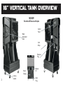
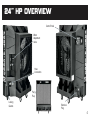
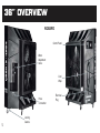
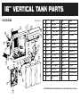
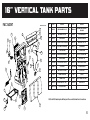
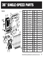
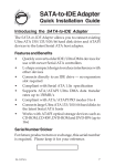
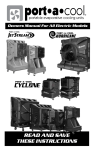
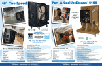
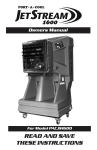
PORTACOOL OWNER’S MANUAL FOR PAC2K482S, PAC2K363S, PAC2K361S, PAC2K36HPVS, PAC2K24HPVS and PAC163SVT TABLE OF CONTENTS READ AND SAVE THESE INSTRUCTIONS CONTENTS: QUICK SETUP GUIDE.......................................................................... page 2 PRODUCT OVERVIEW................................................................... pages 3-7 SAFETY INFORMATION...................................................................... page 8 GENERAL OPERATION................................................................ pages 9-10 MAINTENANCE AND STORAGE....................................................... page 11 STOP TROUBLESHOOTING................................................................. pages 12-13 TECHNICAL SUPPORT AND WARRANTY................................ pages 14-15 EXPLODED VIEWS..................................................................... pages 16-20 WIRING DIAGRAM............................................................................. page 21 FREQUENTLY ASKED QUESTIONS................................................. page 22 DO NO T RETU RN! For questions or comments, please call Portacool Customer Service at 936-598-5651. QUICK SET UP 1 2 Remove box and palette 5 Position product on level surface 3 Fill sump or attach water hose For setup, pads should appear wet before starting the fan. Check the water gauge to monitor water level in tank.The water flow valve on each unit is set at max flow. However, ensure the knob is turned completely to the left before use. Turn to the left to increase water flow. Less water is required for cooling in more humid environments. Fill the tank, then turn on the pump switch and the fan. 4 Plug into appropriate outlet 16" VERTICAL TANK OVERVIEW PAC163SVT This unit does NOT have a hose fill option. Control Panel Water Adjustment Valve Cord Wrap Electrical Plug 3 Locking Casters Water Gauge Manual Fill Drain Plug 24" HP OVERVIEW Control Panel Water Adjustment Valve Hose Connection Pad Flap Locking Casters Electrical Plug 4 36" OVERVIEW PAC2K36HPVS Control Panel Water Adjustment Valve Cord Wrap Hose Connection 5 Locking Casters Electrical Plug 48" OVERVIEW PAC2K482S Water Adjustment Valve Hose Connection Control Panel Cord Wrap Electrical Plug Locking Casters 6 SAFETY INFORMATION OPERATION WARNINGS 1) Not intended for use by children 2) Not intended for use by persons with reduced physical, sensory, or mental capabilities 3) Not intended for use by persons with lack of experience and knowledge, unless they have been given instruction and are supervised during operation 4) Children should be supervised to ensure they do not play with the evaporative cooler SAFE OPERATION To reduce the risk of electric shock, fire, or injury: • • • • • • • • • • • • • Do not operate any product with a damaged cord or plug. Discard product or return to place of purchase for examination and/or repair. Do not run cord under carpeting. Do not cover cord with throw rugs, runners, or similar coverings. Arrange cord away from traffic area so it will not be tripped over. Read instructions and labels carefully. Always unplug the electric cord to the Portacool evaporative cooler before performing inspections or repairs. Plug into three-prong grounded GFCI protected electrical receptacle only. Do not step on or roll over power cord with heavy or sharp objects. Do not operate evaporative cooler unless all pads are securely in place. Remove the plug from the electrical receptacle by pulling on the plug and not the cord. Test the GFCI receptacle or breaker monthly to ensure it is functioning properly. Do not operate near open containers of flammable liquids or gases. Ensure evaporative cooler pumps are running continuously to saturate and wet combustible media when used in close proximity to open flame or spark producing activities. A distance of at least 35 feet away from open flame or sparks is recommended to ensure safe operation. Never wash the evaporative cooler cabinet with a garden hose; water may harm the motor and electrical system. If the product is damaged or malfunctions, do not continue to operate it. Refer to the warranty, troubleshooting or FAQ section, call Portacool, LLC, Technical Support at 1-888-266-5243, or email [email protected]. 7 GENERAL OPERATION Electrical Connection PRODUCT MUST BE IN UPRIGHT POSITION WITH COOLING PADS INSTALLED! All models utilize a single power cord and control switches. Before connecting the plug to an outlet, ensure there is no standing water where the cord may lie or where the operator is standing. The use of separate multiple outlet devices is not recommended. When making electrical connections, ensure compliance to local and national codes. Use only with GFCI Protected Receptacles. Please refer to the Barcode Product Label on the side of the product for specific electrical requirements. OPERATING PROCEDURES Specifications Each Portacool evaporative cooler has its own set of operational specifications, sizes, weights, voltage frequency, current requirements, etc. Please ask for the specifications for your model from your distributor, check the serial number plate, or visit www.portacool.com for the specifications for your product. Placement of the Portacool Evaporative Cooler There are three primary considerations when deciding where to place the Portacool evaporative cooler. 1) Make sure there is a clear, unobstructed path to provide maximum airflow. 2) If the evaporative cooler is positioned on a raised platform, ensure the platform constructed for holding the product is stable, well constructed, and will not allow the product to tip over and that it allows for the full weight of the evaporative cooler including water in the tank. The product must be level and in the upright position. 8 3) If placed near a wall or other obstruction, position the product a minimum of 3 feet (0.9 meters) from the wall or obstruction with pads facing the wall. This allows the unrestricted flow of warm air to the cooling pad side of the product. When using multiple products in close proximity, be sure to aim the product so the air flows complement each other to achieve maximum cooling capacity. Starting the Pump and Adjusting the Water Flow Once the water tank is full, moving the pump switch to the “ON” position will turn on the pump. When initially turning on the pump, the level in the water tank will drop suddenly and restart the flow of supply water. This is a normal condition, as the cooling pads require a large amount of water for proper wetting. When the Portacool evaporative cooler is new, the new pads will require an initial ‘breaking-in’ period. This period is required for the pads to begin readily absorbing water. It may require up to a week to achieve maximum efficiency. It is important to ensure that the spray bar is properly adjusted when first starting the water flow in the Portacool evaporative cooler. Increasing the flow using the water flow valve (see Quick Setup on page 2) makes this adjustment. Proper water adjustment should leave the pads saturated with water, but not flooded. Pads should appear wet. However, cascading amounts of water can actually reduce cooling efficiency. Proper adjustment will prevent problems and increase cooling capacity. When properly adjusted, one or two dry streaks will appear across the pads. When turning the evaporative cooler off at the end of the day or week, the pump should be turned off about 15 minutes before the fan to allow the cooling pads to dry. This will increase the life of the pads. Starting the Portacool Evaporative Cooler COOLING PADS MUST BE INSTALLED AND CASTER LOCKS MUST BE ENGAGED Start the fan by turning the fan switch to the ‘ON’ position. Step slowly through the speeds allowing the fan to obtain its full speed at the LOW speed before going to HIGH. 9 MAINTENANCE & STORAGE MAINTENANCE 1) Keep the product clean to ensure peak operating performance. 2) The rugged, corrosion-resistant construction ensures low maintenance will be required. However, in dusty or dirty environments, optional filters are available from your distributor or at www.portacoolparts.com. Daily Maintenance The pump should be turned off approximately 15 minutes before the fan is turned off. This will allow the cooling pads to dry out and extend their life. This also helps control the growth of mildew, mold, bacteria, and other odor-causing elements. Weekly Maintenance The product should be shut down and the water tank should be drained once a week. Closing the water flow valve and removing the drain plug will accomplish this. Once the water tank is drained and the power disconnected, the pads may be removed to allow cleaning of the water tank. Dust may collect in the water tank over time. Replace pads in correct airflow direction, referring to the label on the pads. Storage 1) Drain all water from the water tank and wipe clean, ensuring the pads and water tank are completely dry. 2) Roll up the electrical power cord and secure it to ensure it will not be rolled over, tripped over, or caught in equipment. 3) Cover the product completely to prevent dust build-up and store in a dry area. This also helps to prevent damage to the pads. Optional dust covers are available from your distributor or at www.portacoolparts.com. 10 TROUBLESHOOTING The Portacool evaporative cooler consists of three systems — the fan system, the electrical system, and the water system. It is important to determine with which of the systems the problem is associated. Certain problems may be associated with more than one system. A careful check of all systems should be made to fully understand the extent of the problem. CAUTION — DISCONNECT POWER BEFORE REMOVING COOLING PADS FROM THE PRODUCT! NOTICE — POWER CORD MAY BE REPLACED ONLY BY THE MANUFACTURER OR QUALIFIED AGENT! Repair and Replacement Procedures Ensure all water is removed from the Portacool evaporative cooler and all power is disconnected. Remove all impediments to access the component you are checking or replacing. REPLACING THE COOLING MEDIA PADS The flap must be removed to allow access to the cooling pads. Start with the center pad, which can be tilted out from the top and lifted out of the drain trough. The two pads to either side of the center pad may then be removed in the same manner. To remove the two outside pads, they must first be pulled sideways toward the center of the Portacool evaporative cooler until they clear the side retainer before removing in the same manner as the other pads. 1) Locate the screw in the rear of the unit on the upper right side of the pad flap. 2) Remove screw and lower pad flap to vertical position. 3) Once the pad flap is moved, grasp the middle pad and tilt out at a 90 degree angle. 4) Pull the pad up to remove from unit. Repeat for other pads. 11 The following troubleshooting guide is intended to address the most common symptoms which may occur. If you are unable to resolve the issue, please call Technical Support. Turn off all power to the evaporative cooler before attempting to troubleshoot any of the following symptoms. SYMPTOM POSSIBLE CAUSES REMEDY Product fails to start or deliver air 1. No electrical power to product 1. Check power A. Circuit breaker tripped A. Reset breaker* B. GFCI tripped B. Reset GFCI* C. Cord(s) unplugged or damaged C. Plug in cord(s) or replace if damaged * If condition persists, call electrician 2. Motor overheated and/or frozen 2. Replace motor Product starts but air delivery inadequate 1. Insufficient air exhaust 1. Open windows or doors 2. Insufficient water – pad not wet 2. Check water distribution system A. Cooling pads plugged A. Clean or replace pads B. Dry streaks on pads B. Check water level C. Large dry spots on pads C. Make sure cooler is level, clean spray bar D. Pump not working D. Clean or replace pump E. Loose water connections E. Check for leaks and correct Water draining from cooler 1. Seat in float valve leaking 1. Replace float valve 2. Drain bushing/cap not tight 2. Tighten fitting and/or cap Musty or unpleasant odor 1. Stale or stagnant water in sump 1. Drain, flush and clean sump 2. Pads mildewed or clogged 2. Replace pads 3. Pads not completely wet before cooler is turned on 3. Turn on pump before starting fan Knocking, shaking, or rattling sounds 1. Loose parts 1. Check and tighten where needed 2. Fan blade rubbing shroud 2. Inspect and adjust, or replace Water droplets in the discharge air stream 1. Too much water delivered to the cooling pads 1. Make sure pads are properly positioned in the frames and product is level 2. Outdoor humidity level is too high or it is raining 2. Use cooler as a fan only (turn pump off) or discontinue use of product until 3. Leaking hoseoutdoor humidity level drops. 3. Tighten connection or replace hose TECHNICAL SUPPORT TECHNICAL SUPPORT Technical support and service is available directly from your distributor or call Portacool, LLC Technical Support Hot Line at 888-266-5243 for the distributor nearest you. You may also contact the Support Hot Line for consultation on troubleshooting and parts replacement. Please have serial number and model number of product available. WARRANTY AND REPLACEMENT PARTS PORTACOOL® Evaporative Cooler Limited Warranty For one (1) year from date of purchase, Portacool, LLC (hereafter “Portacool”) warrants any original component part or parts of its Portacool™ portable evaporative coolers (the “Equipment”) that are found, upon examination by factory-authorized personnel, to be defective in material or workmanship, excepting, however, that the following component motors shall be warranted by Portacool for a period of three (3) years from the date of purchase: MOTOR-013-04, MOTOR-010-07, MOTOR-012-06, MOTOR-012-05 and MOTOR-034-01. All transportation charges for shipment of the Equipment and/or its component parts that are submitted for replacement or repair under this warranty must be borne by the purchaser. If the Equipment and/or its original component parts develop a defect covered by this limited warranty within the applicable time periods described above, the same will be repaired or replaced at Portacool’s option. In the case of a breach of any implied or written warranty relating to the Equipment and/or its component parts, Portacool shall not be liable for any incidental or consequential damages, and the limits of liability against Portacool for any such breach shall not exceed the cost of replacement or repair of the Equipment. This warranty is void if the Equipment and/or its component parts are found to have been misused, abused, repaired by or tampered with by unauthorized or unqualified personnel. 13 RETURNS Returned Merchandise Authorization (RMA) Procedures All Portacool evaporative coolers, parts, or materials being returned to Portacool, LLC for warranty replacement or repair require an RMA (Return Merchandise Authorization) number. Warranty parts can be replaced by: 1. The distributor can purchase the part with an RMA number and will only be charged for the cost of the part, not for the shipping. When the defective part is returned freight paid, the distributor’s account will be credited for the cost of the part. 2. The defective part need to be returned to Portacool, LLC, labeled with the RMA number within 90 days of receipt of replacement parts. 3. The customer / distributor can call Tech Support to get an RMA number to send the defective part back to Portacool, LLC. Once the part is received by Portacool, a replacement part will be sent at no charge. Information needed to get an RMA number: 1. The product serial number or manufacturer date code 2. The product model number (ex. PAC2K363S) 3. The part number or description of the part to be replaced Only major component parts need an RMA number, i.e. fans, motors, pumps, and some plumbing parts. For replacement of small parts, the serial and model numbers are still required, but the parts do not need to be returned to Portacool, LLC. For warranty replacement parts call Portacool® Technical Support at 1-888-266-5243. FAX: 936-598-1431. Shipping Address Mailing Address: Portacool, LLC Portacool, LLC 721 FM 2468 P.O. Box 2167 Center, Texas 75935 Center, Texas 75935 To expedite your request, please submit the RMA form found on our website at info.portacool.com/returnshold 14 16" VERTICAL TANK PARTS PAC2K163SHD REVISED 02/12/15 21 7 1 11 22 22 25 24 24 4 23 2 22 22 15 28 29 20 19 16 9 8 27 3 17 5 26 3 26 3 14 13 10 18 3 # PART # DESCRIPTION # PART # DESCRIPTION 1 BONNET-03 SPRAY BAR BONNET 16 PRES-REG-01 WATER PRESSURE REGULATOR 2 BOX-UL-01 3 SPD ELECTRICAL BOX 17 PUMP BRACKET PLASTIC PUMP COVER/BRACKET 3 CLAMP-01 1/2” CLAMP FOR PLASTIC TUBE 18 PUMP-0150-1 PUMP 1/70HP W/NETTING 4 CTRL-3SPD-02 3-SPD HARNESS W/SALZER SWITCH 19 PVC-ADP-01 3/4 X 1/2 ADAPTER 5 DRAIN-PLUG-01 DRAIN PLUG 16 PAC 20 S-004 1/4-20 X 1/2” BOLT FOR FLOAT 6 FAN-ASSM-15 16” VT FAN BLADE 21 S-006 #12 X 1 1/4” TEK SCREW 7 FLAP-16-01 FRONT FLAP FOR 16” 22 S-009 10-24 x 3/4” TRUSS HEAD SCREW 8 FLOAT-02 FLOAT VALVE 23 SPRAY-07 SPRAY BAR FOR 16” PAC 9 HOSE-FM18 1/2” X 18” F/M HOSE 24 SPRAY-ACC-04 CLAMP FASTENER 1029 10 HOSE-FTG-05 FEM/FEM 3/4” BRASS SWIVEL 25 SWITCHPL-REV3SP SWITCH CVR PLATE REVERSE 3SPD 11 MESH-PAC-05 FAN SCREEN 26 TUBE-01 1/2” PLASTIC TUBE (PER FOOT) 12 MOTOR-012-04E 16” HD,FC,VT 3 SPD MOTOR 27 VALVE-01 1/2” GATE VALVE 13 PAC-PLB-01 BRASS INLET FITTING 28 VENT16-INJ-01 INJECTION MOLDED VENTURI 14 PAD6024/G PAD FOR 16” UNIT (3 per unit) 29 VENTURI-MNT-01 N/S H/D MOTOR MOUNT FRAME 15 POWERCORD-01F 16’ POWER CORD W/STRAIN RELIEF 6 220/50 and 220/60 models require additional parts. Please contact Customer Service for assistance 12 16" VERTICAL TANK PARTS PAC163SVT PART # DESCRIPTION # PART # DESCRIPTION 1 BASE-JS/VT CASTER BASE ASSEMBLY FOR JS/VT 16 POWERCORD-03F 10FT POWER CORD W/STRAIN RELIEF/ NUT/WASHER 22 2 BONNET-03 SPRAY BAR BONNET FOR 16” PAC 17 PAD6024/G 16” PAC REPLACEMENT PAD 3 BOX-UL-01 3SPD ELECTRICAL BOX 18 POLY-FTG-06 90DEG FITTING FOR SIGHT TUBE PUMP ASSEMBLY FOR 16” UNIT REVISED 02/17/2015 2 21 25 # 11 24 14 3 24 6 23 26 4 CASTERS-HD-4 4” JS/VT HEAVY DUTY NON-LOCKING CASTER 19 PUMP-0140-1 7 5 CASTERS-HD-4L 4” JS/VT HEAVY DUTY LOCKING CASTER 20 PUMP-ACC-17 JS/VS PUMP BRACKET 6 CLAMP-01 1/2” WIRE SPRING CLAMP 21 S-006 12-14 BLACK TEC SCREW 10-24 X 3/4” TRUSS HEAD SCREW 28 13 8 20 16 12 26 6 19 18 4 9 27 7 CTRL-VLV-BRKT-1 CONTROL VALVE MOUNTING BRACKET 22 S-009 8 CTRL-3SPD-02 3SPD SWITCH HARNESS 23 SPRAY-07 SPRAY BAR FOR 16” PAC 9 DRAIN-PLUG-34 1/4” NPT PLUG #P-28 FOR 16”UNIT 24 SPRAY-ACC-04 CLAMP FASTENER FOR SPRAY BAR 10 FAN-ASSM-15 16” VT FAN BLADE 25 SWITCHPL-REV3SP 3SPD SWITCH COVER PLATE 11 FLAP-16-01 FRONT FLAP FOR 16” JETSTREAM 26 TUBE-01 SOFT PLASTIC TUBE 12 JS-ACC-01 2” THREADED FILLER CAP RING 27 TUBE-03 SIGHT TUBE 13 JS-ACC-02 2” THREADED FILLER CAP 28 VALVE-01 PUMP TO SPRAYBAR CONTROL VALVE 14 MESH-PAC-05 FAN GUARD SCREEN FOR 16” UNITS 29 VENT16-INJ-01 VENTURI FOR 16” FAN 15 MOTOR-012-04E 16” HD, FC,VT 3SPD MOTOR 1 10 24 22 220/50 and 220/60 models require additional parts. Please contact Customer Service for assistance 5 29 15 17 16 24" HIGH PERFORMANCE PARTS PAC2K24HPVS 35 8 Revised 02/25/15 12 18 30 32 3 5 4 34 34 28 33 15 17 22 37 10 9 14 1 24 29 6 31 20 7 16 25 21 27 26 23 13 7 2 19 11 38 # PART # DESCRIPTION # PART # DESCRIPTION 1 BASE-2K24 CADDY 20 LOCKNUT-FNG-516 5/16-18 FLANGE NYLON INSERT LOCK NUT 2 BLADE-ASSM-02 VOSTERMAN 24” FAN BLADE ASSY. (33deg.) 21 PAC-PLB-01 BRASS INLET FITTING 3 BONNET-02 SPRAY BAR BONNET FOR 24” PAC 22 PAC-PLB-02 BLACK PLUMBING ASSEMBLY PAD FOR 24” PAC (4 per unit) 4 BOX-UL-03 VARIABLE SPEED ELECTRICAL BOX 23 PAD6036/G 5 BRACE-24-01 BONNET STEEL BAR 24 POWERCORD-01F 16’ POWER CORD ASSEMBLY 6 CASTERS-HD-4 SWIVEL CASTER 25 PRES-REG-01 WATER PRESSURE REGULATER 7 CASTERS-HD-4L LOCKING SWIVEL CASTER 26 PUMP-016-4Z SUBMERSIBLE 1/6 HP PUMP 8 CTRL-KNOB-02 D-SHAFT KNOB FOR CONTROL SWITCH 27 PUMP-ACC-15 PUMP BRACKET- 1/6 HP PUMP 24” PAC 9 CRTL-VS-02 SWITCH SET FOR 24” HPVS UNIT 28 PVC-ADP-01 3/4” X 1/2” REDUCING ADAPTER 10 DRAIN-01 1/2” BOILER DRAIN 29 S-004 1/4-20 X 1/2” BOLT FOR FLOAT 11 FAN24HP-MNT-01 MOTOR MOUNT ARM FOR 24” HPVS UNIT 30 S-006 #12 X 1 1/4” TEK SCREW 12 FLAP-24-01 FRONT FLAP FOR 24” PAC 31 S-007 5/16” TRUSS HEAD SCREW FOR CASTER 13 FLOAT-02 FLOAT VALVE 32 S-009 10-24 X 3/4” TRUSS HEAD SCREW 14 HOSE-FF30 1/2” X 30” FEM/FEM HOSE TO PLB TO PUMP 33 SPRAY-04 SPRAY BAR FOR 24” PAC 15 HOSE-FF37 1/2” X 37” FEM/FEM HOSE TO SPRAYBAR TO PLB 34 SPRAY-ACC-04 CLAMP FASTENER 1029 16 HOSE-FM22 1/2” X 22” MALE/FEMALE HOSE TO FLOAT 35 SWITCHPL-VSPD-T SWITCH PLATE FOR HP UNIT PAD TROUGH FOR 24” PAC 17 HOSE-FTG-05 FEM/FEM 3/4” X 3/4” BRASS SWIVEL 36 TROUGH-02 18 MESH-PAC-03 FAN SCREEN FOR 24” PAC 37 VALVE-01 1/2” GATE VALVE 19 MOTOR-012-06 1/3 HP DIRECT DRIVE VOSTERMAN MOTOR 38 VENTURI-24-02 PLASTIC VENTURI FOR 24”HPVS UNIT 36 220/50 and 220/60 models require additional parts. Please contact Customer Service for assistance 36" SINGLE-SPEED PARTS PAC2K361S PART # DESCRIPTION # PART # DESCRIPTION 1 BASE-2K36 CADDY 21 MOTOR-MNT-01 MOUNT FOR 36” MOTOR 34 2 BEARING-FAN-01 BEARING FOR 24” & 36” PAC 22 N-516-NYLOK 5/16” NYLOCK NUT FOR CASTERS 6 3 BELT2K-38-01 A-38 FAN BELT 23 PAC-PLB-01 BRASS INLET FITTING 4 BONNET-01 SPRAY BAR BONNET 24 PAD6048/G PAD FOR 36” PAC (5 per unit) 5 BOX-UL-02 1 SPD ELECTRICAL BOX 25 POWERCORD-01F POWER CORD ASSEMBLY 6 BRACE-36-02 BONNET BRACE 26 PRES-REG-01 WATER PRESSURE REGULATOR 7 BRACE-36-03 36” PULTRUSION ASSEMBLY 27 PULLEY-3.75 3.75 O.D. PULLEY 15 8 CASTERS-HD-4 HEAVY DUTY CASTER 28 PUMP-016-4Z L/G 1/6HP SUBMERSIBLE PUMP 9 CASTERS-HD-4L HEAVY DUTY LOCKING CASTER 29 PUMP-ACC-13 SUBMERSIBLE PUMP BRACE 28 10 CTRL-1SPD-01 1 SPEED SWITCH SET 30 PVC-ADP-01 3/4” X 1/2” REDUCING ADAPTER 1/4-20 X 1/2” BOLT FOR FLOAT 13 19 32 4 37 36 16 10 5 26 30 22 12 40 23 35 39 29 24 14 2 33 9 17 31 1 36 11 18 25 8 # Revised 02/25/15 3 7 27 38 21 20 11 DRAIN-01 1/2” BOILER DRAIN VALVE 31 S-004 12 FAN-ASSM-01 PLASTIC BLADE & HUB ASSEMBLY FOR 36” PAC 32 S-006 #12 X 1 1/4” TEK SCREW 13 FLAP-36-01 FRONT FLAP FOR 36” 33 S-007 5/16-18 TRUSS HEAD SCREW 14 FLOAT-02 FLOAT VALVE 34 S-009 10-24 X 3/4” TRUSS HEAD SCREW 15 HOSE-FF24 1/2” X 24” FEM/FEM HOSE PUMP TO PLB 35 SPRAY-06 SPRAY BAR FOR 36” PAC 16 HOSE-FF50 1/2” X 50” FEM/FEM HOSE PLB TO SPRAYBAR 36 SPRAY-ACC-04 CLAMP FASTENER 1029 17 HOSE-FM30 1/2” X 30”FEM/MALE HOSE INLET TO FLOAT 37 SWITCHPL-1SPD SWITCH COVER PLATE 18 HOSE-FTG-05 FEM/FEM 3/4” BRASS SWIVEL 38 TROUGH-01 PAD TROUGH FOR 36” PAC 19 MESH-PAC-02 FAN SCREEN 39 VALVE-01 1/2” GATE VALVE MOTOR-012-01STA 1SPD STUD MOUNT MOTOR (PRODUCED W/9K922B) 40 VENTURI-36-01 36” RTM FAN VENTURI 20 220/50 and 220/60 models require additional parts. Please contact Customer Service for assistance 18 36" THREE-SPEED PARTS PAC2K363S Revised 02/25/15 13 20 33 38 34 4 6 37 17 37 36 40 10 11 5 27 24 19 26 16 29 15 1 18 32 23 8 8 41 9 25 14 9 35 31 30 2 12 3 7 28 39 22 21 # PART # DESCRIPTION # PART # DESCRIPTION 1 BASE-2K36 CADDY 22 MOTOR-MNT-01 MOUNT FOR 36” MOTOR 2 BEARING-FAN-01 BEARING FOR 24”/36” FAN BLADE ASSEMBLY 23 N-516-NYLOK 5/16” NYLOCK NUT FOR CASTERS 3 BELT2K-38-01 A-38 FAN BELT 24 PAC-PLB-01 BRASS INLET FITTING 4 BONNET-01 SPRAY BAR BONNET 25 PAD6048/G PAD FOR 36” PAC (5 per unit) 5 BOX-UL-04 3 SPD ELECTRICAL BOX 26 POWERCORD-01F 16’ ELECTRICAL CORD 6 BRACE-36-02 BONNET BRACE 27 PRES-REG-01 WATER PRESSURE REGULATOR 7 BRACE-36-03 36” PULTRUSION ASSEMBLY 28 PULLEY-3.75 3.75 O.D. PULLEY 8 CASTERS-HD-4 HEAVY DUTY SWIVEL CASTER 29 PUMP-016-4Z 1/6 HP SUBMERSIBLE PUMP FOR 36” PAC 9 CASTERS-HD-4L HEAVY DUTY LOCKING SWIVEL CASTER 30 PUMP-ACC-13 PUMP BRACE 10 CTRL-3SPD-02 3 SPEED SALZER SWITCH SET 31 PVC-ADP-01 3/4”X1/2” REDUCING ADAPTER 1/4-20 X 1/2” BOLT FOR FLOAT 11 DRAIN-01 1/2” BOILER DRAIN VALVE 32 S-004 12 FAN-ASSM-01 PLASTIC BLADE & HUB ASSEMBLY 33 S-006 #12 X 1 1/4” TEK SCREW 13 FLAP-36-01 FRONT FLAP FOR 36” 34 S-007 5/16-18 TRUSS HEAD SCREW 14 FLOAT-02 FLOAT VALVE 35 S-009 10-24 X 3/4” TRUSS HEAD SCREW 15 FLOATSWITCH-01 WATER PUMP SHUT OFF SWITCH 36 SPRAY-06 SPRAY BAR FOR 36” PAC 16 HOSE-FF24 1/2” X 24” FEM/FEM HOSE PLB TO PUMP 37 SPRAY-ACC-04 CLAMP FASTENER 1029 17 HOSE-FF50 1/2” X 50” FEM/FEM HOSE SPRAY BAR TO PLB 38 SWITCHPL-3SPD SWITCH COVER PLATE - 3SPD 18 HOSE-FM30 1/2” X 30” MALE/FEM HOSE INLET TO FLOAT 39 TROUGH-01 PAD TROUGH FOR 36” PAC 19 HOSE-FTG-07 FEM/FEM 3/4” BRASS SWIVEL 40 VALVE-01 1/2” GATE VALVE 20 MESH-PAC-02 FAN SCREEN 41 VENTURI-36-01 36” FAN VENTURI 21 MOTOR-012-02STA 3 SPD MOTOR 220/50 and 220/60 models require additional parts. Please contact Customer Service for assistance 36" VARIABLE SPEED PARTS PAC2K36HPVS 32 37 8 Revised 02/25/15 13 5 20 33 3 36 36 4 9 17 29 27 23 19 15 26 6 18 31 34 7 14 11 22 21 2 40 39 24 16 28 1 12 38 30 35 10 25 ITEM # PART # DESCRIPTION ITEM # PART # DESCRIPTION 1 BASE-2K36 CADDY 21 MOTOR-012-05 1/2 HP DIRECT DRIVE VOSTERMAN MOTOR 2 BLADE-ASSM-01 VOSTERMAN 36” FAN BLADE ASSEMBLY 22 N-516-NYLOK 5/16-18 NYLOK NUT 3 BONNET-01 SPRAY BAR BONNET FOR 36” PAC 23 PAC-PLB-01 BRASS INLET FITTING PAD FOR 36” PAC (5 per unit) 4 BOX-UL-06 VARIABLE SPEED ELECTRICAL BOX 24 PAD6048/G 5 BRACE-36-02 BONNET BRACE 25 POWERCORD-01F ELECTRICAL CORD FOR PAC 6 CASTERS-HD-4 HEAVY DUTYSWIVEL CASTER 26 PRES-REG-01 WATER PRESSURE REGULATER 7 CASTERS-HD-4L HEAVY DUTY LOCKING SWIVEL CASTER 27 PUMP-016-4Z SUBMERSIBLE 1/6 HP PUMP 8 CTRL-KNOB-01 LONG EXT. KNOB FOR CONTROL SWITCH 28 PUMP-ACC-13 PUMP BRACKET- 1/6 HP PUMP 9 CTRL-VS-01 VAR. SPD. SWITCH SET FOR 36” HPVS 29 PVC-ADP-01 3/4” X 1/2” REDUCING ADAPTER 10 DRAIN-01 1/2” BOILER DRAIN 30 S-004 1/4-20 X 1/2” BOLT FOR FLOAT 11 FANHP-BOOTS BOOTS FOR 36” MTR CONNECTS TO ARMS 31 S-006 #12 X 1 1/4” TEK SCREW 12 FAN36HP-MNT-01 PI-CO 3VP1006 MOTOR SUPPORT ARM36” PAC 32 S-007 5/16-18 TRUSS HEAD SCREW 13 FLAP-36-01 FRONT FLAP FOR 36” PAC 33 S-009 10-24 X 3/4” TRUSS HEAD SCREW SPRAY BAR FOR 36” PAC 14 FLOAT-02 FLOAT VALVE 34 SPRAY-06 15 FLOATSWITCH-01 WATER PUMP SHUT OFF SWITCH 35 SPRAY-ACC-04 CLAMP FASTENER 1029 16 HOSE-FF24 FEM/FEM HOSE 24” LONG 36 SWITCHPL-VSPD-T SWITCH COVER PLATE VAR. SPD. PAD TROUGH FOR 36” PAC 17 HOSE-FF50 FEM/FEM HOSE 50” LONG 37 TROUGH-01 18 HOSE-FM30 FEM/MALE HOSE 30” LONG 38 VALVE-01 1/2” GATE VALVE 19 HOSE-FTG-07 FEM/FEM 3/4” BRASS SWIVEL 39 VENTURI-36-01 36” FAN VENTURI 20 MESH-PAC-02 FAN SCREEN FOR 36” PAC 220/50 and 220/60 models require additional parts. Please contact Customer Service for assistance 20 48" TWO-SPEED PARTS PAC2K482S 36 11 18 33 REVISION 02/17/15 31 5 3 35 8 4 26 14 22 17 13 32 30 6 21 15 23 16 25 34 12 35 39 9 28 24 29 1 7 40 2 38 10 27 20 21 19 37 # PART # DESCRIPTION # PART # DESCRIPTION 1 BASE-2K48 CADDY 21 N-516-NYLOK 5/16-18 NYLOK NUT FOR CASTERS 2 BELT2K-45-01 A-45 FAN BELT 22 PAC-PLB-01 BRASS INLET FITTING 3 BONNET-04 SPRAY BAR BONNET 23 PAC-PLB-02 BLACK PLUMBING ASSEMBLY PAD FOR 48” PAC (6 per unit) 4 BOX-UL-02 2 SPD ELECTRICAL BOX 24 PAD6060/G 5 BRACE-48-03 BRACE FOR BONNET 25 POWERCORD-01F ELECTRICAL POWER CORD 6 CASTERS-8 8” CASTERS 26 PRES-REG-01 WATER PRESSURE REGULATOR 7 CASTERS-8L 8” LOCKING CASTERS 27 PULLEY-3.25 3.25 MOTOR PULLEY 8 CTRL-2SPD-01 2 SPEED SWITCH SET 28 PUMP-016-4Z L/G 1/6HP SUBMERSIBLE PUMP 9 DRAIN-01 1/2” BOILER DRAIN VALVE 29 PVC-ADP-01 3/4” X 1/2” ADAPTER 10 FAN-ASSM-05 FAN BLADE ASSEMBLY FOR 48” UNIT 30 S-004 1/4-20 X 1/2” BOLT FOR FLOAT 11 FLAP-48-01 FRONT FLAP FOR 48” PAC 31 S-006 #12 X 1 1/4” TEK SCREW 12 FLOAT-02 FLOAT VALVE 32 S-007 5/16-18 TRUSS HEAD SCREW FOR CASTERS 13 FLOATSWITCH-01 WATER PUMP SHUT OFF SWITCH 33 S-009 10-24 X 3/4” TRUSS HEAD SCREW 14 HOSE-FF37 1/2” X 37” FEM/FEM HOSE PLB TO PUMP 34 SPRAY-08 SPRAY BAR FOR 48” PAC 15 HOSE-FF68 1/2” X 68” FEM/FEM HOSE SPRAY BAR TO PLB 35 SPRAY-ACC-04 CLAMP FASTENER 1029 16 HOSE-FM25 1/2” X 25” MALE/FEM HOSE INLET TO FLOAT 36 SWITCHPL-2SPD 2SPD SWITCH COVER PLATE 17 HOSE-FTG-05 FEM/FEM 3/4” X 3/4” SWIVEL 37 TROUGH-03 PAD TROUGH FOR 48” PAC 18 MESH-PAC-06 FAN SCREEN 38 UPRIGHTS-48 UPRIGHT FOR 48” UNIT 19 MOTOR-010-01 1HP/2SPD MOTOR FOR 48” UNIT 39 VALVE-01 1/2” GATE VALVE 20 MOTOR-MNT-48 MOTOR MOUNT FOR 48” UNIT 40 VENTURI-48-02 VENTURI FOR 48” PAC FAN ASSEMBLY 220/50 and 220/60 models require additional parts. Please contact Customer Service for assistance VARIABLE SPD WIRING DIAGRAM 22 ONE-SPEED WIRING DIAGRAM 23 TWO-SPEED WIRING DIAGRAM 24 THREE-SPEED WIRING DIAGRAM 25 FREQUENTLY ASKED QUESTIONS Q. WHAT ASSEMBLY IS REQUIRED? A. None. Portacool evaporative coolers are ready to use right out of the box. Q. HOW DO I PREPARE MY PORTACOOL PRODUCT FOR STORAGE? A. Drain the product, dry out the pads, cover the product, and store in a dry place. Q. I JUST RAN THE EVAPORATIVE COOLER FOR THE FIRST TIME AND THERE’S AN UNPLEASANT ODOR! A. The pads, located in the back of your Portacool product, have never been wet before. The resin in the pads will emit an odor the first time you wet them that lasts approximately one to three weeks. Keep the product in an open area until the odor goes away or put a capful of laundry softener directly in the tank in the bottom of your product. After approximately two weeks of operation, the odor should disappear. Q. MY PORTACOOL PRODUCT ISN’T PUTTING OUT ANY COOL AIR. A. First, make sure the water source and electricity source are connected and working. Second, check to see if the pads are damp. If not, adjust the water flow with the water adjustment valve. Third, make sure there is water in the tank. It should be allowed to fill before you turn the pump on. Q. WHAT IS THE BEST ENVIRONMENT TO PRODUCE THE MOST COOL AIR? A. For optimum performance, the temperature should be 85˚ F or higher and the relative humidity should be below 75%. However, Portacool products will reduce the temperature in almost any environment, making it more pleasant. Q. HOW OFTEN DO PADS HAVE TO BE REPLACED? A. Depending on the quality of maintenance and frequency of use, pads typically last up to five years. Q. WHAT IS THE DIFFERENCE BETWEEN EVAPORATIVE COOLING AND MISTING SYSTEMS? A. Misting units spray a shower of water into the air that will collect on people, objects, equipment, floors, etc. Portacool products use the process of evaporation to produce cooler air, but do not discharge a mist. Q. WHERE CAN I BUY REPLACEMENT PARTS? A. Replacement parts may be purchased from any Portacool product distributor or directly from Portacool Parts/Technical Support department. You may also visit www. portacoolparts.com to order online. Q. WHAT IS THE AMOUNT OF MOISTURE PRODUCED? A. An increase in humidity of approximately two to five percent is produced, depending on the temperature and humidity of the environment. This increase is not noticeable in a ventilated area where the air produced by the unit is exhausted. Q. HOW LONG WILL THE WATER SUPPLY LAST IN THE TANK? A. With no direct water source available, the water will evaporate in a filled water tank within two to 10 hours of operation, depending on the water capacity of the product, ambient conditions, temperature, and humidity. A water source for refilling the tank is recommended by the manufacturer. Q. WHERE ARE THE MODEL AND SERIAL NUMBERS FOUND? A. The model number can be found on a metal plate on the outside of the product. Model numbers begin with the letters “PAC.” Serial numbers are all-digits. Q. WHAT IF MY QUESTIONS AREN’T ANSWERED HERE? A. Our Tech Support staff is available 8 a.m. to 5 p.m. Central Time, Monday though Friday at 1-888-COOL-AID or you can e-mail them at [email protected]. The manual is available in other languages. To download a digital copy, please visit www.portacool.com. CUSTOMER SERVICE CONTACT 1-936-598-5651 • 1-800-695-2942 [email protected] TECHNICAL/PARTS CONTACT 1-936-598-5651 • 1-888-COOLAID [email protected] VISIT PORTACOOL.COM OR CALL 1-936-598-5651 FOR MORE INFORMATION El manual está disponible en otros idiomas. Para descargar una copia digital, por favor visite www.portacool.com. Le manuel est disponible en d’autres langues. Pour télécharger une copie numérique, se il vous plaît visitez www.portacool.com. لتحميل.والدليل هو متاح في اللغات الأخرى www.portacool.com يرجى ز يارة،نسخة رقمية MANR0003 Portacool, LLC • Manufacturer of Portacool™ portable evaporative coolers and KÜÜL® Pads evaporative media 709 Southview Circle • Center, Texas 75935 • 936-598-5651 • www.portacool.com • www.kuulpads.com