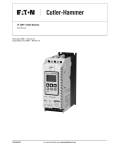
Download S811 SOFTSTARTER
Transcript
1.2 1 Reduced Voltage Motor Starters Solid-State Starters Contents Type S811, Soft Starters with DIM Description 1 Page Type S611, Solid-State Soft Starters . . . . . . . . . . . Type S801, Soft Starters. . . . . . . . . . . . . . . . . . . . . Type S811, Soft Starters with DIM Operation . . . . . . . . . . . . . . . . . . . . . . . . . . . . . Features and Benefits . . . . . . . . . . . . . . . . . . . Standards and Certifications . . . . . . . . . . . . . . Instructional Leaflets . . . . . . . . . . . . . . . . . . . . Catalog Number Selection . . . . . . . . . . . . . . . . Product Selection . . . . . . . . . . . . . . . . . . . . . . . Accessories . . . . . . . . . . . . . . . . . . . . . . . . . . . Options . . . . . . . . . . . . . . . . . . . . . . . . . . . . . . Technical Data and Specifications . . . . . . . . . . Wiring Diagrams . . . . . . . . . . . . . . . . . . . . . . . Dimensions . . . . . . . . . . . . . . . . . . . . . . . . . . . 1 1 1 1 1 1 1 V6-T1-39 V6-T1-56 V6-T1-86 V6-T1-89 V6-T1-92 V6-T1-92 V6-T1-92 V6-T1-93 V6-T1-107 V6-T1-108 V6-T1-109 V6-T1-113 V6-T1-114 1 1 Type S811, Soft Starters with DIM 1 Product Description Application Description Eaton’s S811 offers all the popular features of the S801, but adds enhanced functionality with the new DIM (Digital Interface Module), communications, metering, monitoring and diagnostics capabilities. Designed to control the acceleration and deceleration of three-phase motors, the S811 soft starter uses SCRs to control the voltage to soft start and soft stop the motor. After the motor is started, internal run bypass contactors close, resulting in the motor running directly across-the-line. The built-in solid-state overload protects the motor from overload conditions with sophisticated algorithms that model true motor heating, resulting in better motor protection and fewer nuisance trips. Advanced protective and diagnostic features reduce downtime. 1 1 1 1 1 1 1 1 1 1 1 1 1 1 Eaton’s line of S811 reduced voltage soft starters is very compact, multi-functional, easy to install and easy to set operating parameters. Designed to control the acceleration and deceleration of three-phase motors up to 690V, the line is available from 11–1000A. The S811 is designed to be a complete package combining the silicon controlled rectifiers (SCRs), bypass contactor and overload in one, very compact unit. The S811 is available as a component for panel mounting, in motor control centers or in enclosed control (NEMA Type 1, 3R, 4, 4X, 7/9 and 12). 1 1 A voltage ramp start or current limit start is available. Kick start is available in either starting mode. The soft stop option allows for a ramp stop time that is longer than the coast to stop time. The pump control option provides a smooth transition for starting and stopping a motor and eliminating the “waterhammer” effect that can damage pipes, valves and pumps. The S811 offers an impressive array of advanced protective features. Not only are the protective features selectable, but many offer variable settings and adjustable time delays to ride through system discrepancies. The S811 has an easy to use Digital Interface Module (DIM) that allows the user to configure the device and to read system parameters and monitor system values. The DIM includes an LCD display and keypad to scroll through the various menus. The DIM allows the user to modify control parameters, enable or disable protections, set communication variables, monitor system parameters such as line voltages and currents, and access the fault queue. 1 1 V6-T1-84 Volume 6—Solid-State Motor Control CA08100007E—January 2012 www.eaton.com The DIM can be removed from the S811 and remote mounted. Kits are available to door mount the DIM, enabling users to safely configure, commission, monitor and troubleshoot the system at the electrical panel without opening the enclosure door. This will help eliminate the possibility of an arc flash incident. Digital Interface Module (DIM) ONLN SS OXFDO1 H STOP Monitoring PREV ESC NEXT ENTER 1.2 Reduced Voltage Motor Starters Solid-State Starters Communications The S811 has built-in communication capabilities through Eaton’s QC (Quick Connect) Port. QCPort™ enables the soft starter to be connected to a variety of networks, including DeviceNet™, EtherNet/Modbus, EtherNet/ IP and PROFIBUS. The advantage of QCPort is that multiple control components can be connected to one Eaton D77D gateway. The gateway concentrates data from the devices into a single node. Configuration is simple—a single press of the gateway’s Auto Configuration button sets the system up for default operation. This automatically configures the I/O assemblies to the QCPort system devices. The data from these devices are then assembled into single input and output messages 1 The S811 communication parameters can be configured with the DIM or through the Fieldbus using CH Studio Component Manager. Advanced communication configuration settings provide the system integrator with powerful tools to facilitate system optimization 1 1 1 1 1 1 1 S811 Connection Communications Reference Description Part Number DeviceNet network adapter D77D-DNA EtherNet Modbus network adapter D77D-EMA EtherNet/IP network adapter D77D-EIP PROFIBUS network adapter D77D-PNA Terminator and power tap D77E-QPLR DIN rail communications backplane, 7-position D77E-BP7 DIN rail communications backplane, 12-position D77E-BP12 85–264 Vac input, 24 Vdc output PSG240E 360–575 Vac input, 24 Vdc output PSG240F 24 Vdc Power Supply Fieldbus 1 1 1 1 Network Adapter (Gateway) 1 Terminator and Power Tap 1 DIM 1 1 S811 Soft Starter +– 1 0 DIN Rail Communications Backplane 1 1 1 1 1 1 1 1 1 1 1 1 1 1 Volume 6—Solid-State Motor Control CA08100007E—January 2012 www.eaton.com V6-T1-85 1.2 Reduced Voltage Motor Starters Solid-State Starters 1 Operation 1 Starting and Stopping Modes The S811 has a variety of starting and stopping methods to provide superior performance in the most demanding applications. The motor can be started in either voltage ramp start or current limit start mode. Kick start and soft stop are available within both starting modes. 1 1 Starting Characteristics—Ramp Start 1 1 1 1 1 1 1 Locked Rotor Torque 1 Voltage Ramp Start Provides a voltage ramp to the motor resulting in a constant torque increase. The most commonly used form of soft start, this start mode allows you to set the initial torque value and the duration of the ramp to full voltage conditions. Bypass contactors close after ramp time. 1 ● ● Adjustable initial torque 0–85% of locked rotor torque Adjustable ramp time 0.5–180 seconds (can be extended with factory modification) 100% Run (FLA) Initial Torque 1 Time (Seconds) 1 1 1 1 1 1 1 Current Limit Start Limits the maximum current available to the motor during the start phase. This mode of soft starting is used when it becomes necessary to limit the maximum starting current due to long start times or to protect the motor. This start ● Maximum current of 0–85% locked rotor current Adjustable ramp time 0.5–180 seconds (can be extended with factory modification) Max. Allowed Current 1 ● Starting Characteristics—Current Limit Start 1 1 mode allows you to set the maximum starting current as a percentage of locked rotor current and the duration of the current limit. Bypass contactors close after current limit time. Run 100% FLA 1 1 Time (Seconds) 1 1 1 1 V6-T1-86 Volume 6—Solid-State Motor Control CA08100007E—January 2012 www.eaton.com Reduced Voltage Motor Starters Solid-State Starters Kick Start Selectable feature in both voltage ramp start and current limit start modes. Provides a current and torque “kick” for 0 to 2.0 seconds. This provides greater initial current to develop additional torque to breakaway a high friction load. ● ● 1.2 1 0–85% of locked rotor torque 0–2.0 seconds duration 1 1 1 1 1 Starting Characteristics—Kick Start 100% 1 Locked Rotor Torque 1 1 1 Run (FLA) Kick Start 1 1 Ramp 1 Time (Seconds) 1 Soft Stop Allows for a controlled stopping of a load. Used when a stop-time that is greater than the coast-to-stop time is desired. Often used with high friction loads where a sudden stop may cause system or load damage. ● 1 Stop time = 0–60 seconds 1 1 1 1 Starting Characteristics—Soft Stop 1 1 Run 1 1 1 1 Ramp Time (Seconds) 1 1 1 1 1 Volume 6—Solid-State Motor Control CA08100007E—January 2012 www.eaton.com V6-T1-87 1.2 1 1 1 1 1 1 1 1 1 1 1 Reduced Voltage Motor Starters Solid-State Starters Edge and Level Sensing Control Edge Sensing Edge sensing requires +24 Vdc power be momentarily applied to Pin 1 (with terminal P at +24 Vdc) to initiate a start under all conditions. After a stop or fault occurs, the +24 Vdc must be removed, then reapplied to pin 1 before another start can occur. This control configuration should be used when restarting of the motor after a fault or stop must be supervised manually or as a part of a control scheme. The cycling of +24 Vdc power to Terminal 1 before starting is required regardless of the position of the auto reset switch on the DIM. 1 1 Level Sensing Level sensing will enable a motor to restart after a fault is cleared without cycling +24 Vdc power to Terminal 1 as long as: ● ● ● Note: If the auto reset feature is used, CAUTION must be exercised to ensure that any restart occurs in a safe manner. Terminal P is supplied with +24 Vdc (to start from Terminal Block, Input #3 must also be enabled) The auto reset switch on the DIM is set to enabled All faults have been reset This control configuration should be used where it is desirable to restart a motor after a fault without additional manual or automatic control. An example of this condition would be on a remote pumping station where it is desirable to automatically restart a pump after a power outage without operator intervention. 1 1 1 1 1 1 1 1 1 1 1 1 1 1 1 1 1 V6-T1-88 Volume 6—Solid-State Motor Control CA08100007E—January 2012 www.eaton.com Reduced Voltage Motor Starters Solid-State Starters 1.2 Features and Benefits ● ● ● ● Communication capabilities with various protocols The DIM (Digital Interface Module) provides an intuitive, easy-to-use human interface with powerful configuration capabilities to maximize system performance Door or device mounted DIM enables users to safely configure, commission, monitor and troubleshoot the system at the electrical panel without opening the enclosure door, eliminating the possibility of an arc flash incident System operating parameters can be monitored enterprise-wide through a communications network. Increase uptime by providing data for process management and preventive diagnostics ● ● ● Run internal bypass mode greatly reduces internal heating created by the greater power dissipation in the SCRs. Bypass contactor directly connects the motor to the line and improves system efficiency by reducing internal power losses Internal solid-state overload protection provides accurate current measurement and trip settings. Sophisticated algorithms solve a series of differential equations that model true motor heating and cooling, resulting in superior motor overload protection while minimizing nuisance trips. Advanced selectable protective features safeguard the motor and system against a variety of system faults Internal run bypass contactors and overload protection eliminate the need for additional devices, reducing enclosure sizes, minimizing installation and wiring time, and reducing overall assembly size and cost ● ● ● ● ● Wide range of overload FLA settings (31–100% of rated current) and a selectable trip class (5–30) offers users the flexibility to fine tune the starter to match specific application requirements Variable ramp times and torque control settings provide unlimited starting configurations, allowing for maximum application flexibility Kick-start feature enables soft starting of high friction loads Soft stop control for applications where an abrupt stop of the load is not acceptable Pump control option with sophisticated pump algorithms on both starting and stopping that minimize the pressure surges that cause water hammer. The pump control option will maximize the life of the pump and piping systems while minimizing the downtime caused by system failure ● ● ● ● ● ● Six SCRs control all three motor phases, providing smooth acceleration and deceleration performance Soft acceleration and deceleration reduces wear on belts, gears, chains, clutches, shafts and bearings Reduce the peak inrush current’s stress on the power system Manage peak starting torque to diminish mechanical system wear and damage 24 Vdc control voltage enhances personnel and equipment safety Removable, lockable control terminal block reduces maintenance costs. Also provides the opportunity for OEMs to reduce assembly and test costs by utilizing preassembled wire harnesses The S811 calculates a thermal memory value based on the heat energy introduced into the motor during the start process. A 100% value represents the maximum safe internal temperature of the motor. When the thermal memory value reaches 100%, an overload trip will occur removing power to the motor. Upon trip, the S811 stores the calculated motor heating value and will not allow a motor re-start until the motor has a thermal memory value of less than 100%. This feature ensures the motor will not be damaged by repeated overload trip, reset and restart cycles. The thermal memory value can be monitored through the DIM or the communications network. The thermal memory value can be of great use in determining an impending overload trip condition.Alarms can be implemented in the process monitoring system warning of an impending trip before a trip occurs halting the process. Costly system downtime can be avoided. The trip current is adjusted to match the specific application requirements by entering the motor nameplate full load current rating and trip class. The FLA parameter is adjustable from 32% to 100% of the unit’s rated current. The overload trip class is adjustable from class 5 through class 30. The overload is ambient temperature compensated—meaning its trip characteristics will not vary with changes in ambient temperature. The overload protection can be enabled, disabled, or disabled on start. 1 1 1 1 1 1 1 1 1 1 1 1 1 1 1 1 Protective Features All protective features can be configured, enabled or disabled with the DIM or through the communications network. Motor Overload The S811 includes electronic overload protection as standard. The overload meets applicable requirements for a motor overload protective device. The overload protects the motor from over heat conditions with the use of sophisticated algorithms that model true motor heating, resulting in superior motor protection and fewer nuisance trips. 1 1 Short Circuit The use of a short-circuit protective device in coordination with the S811 is required in branch motor circuits by most electrical codes. Short-circuit coordination ratings with both fuses and Eaton molded case circuit breakers are available providing customers with design flexibility. The S811 has short-circuit coordination ratings as an open component, an enclosed starter, and in a motor control center. Volume 6—Solid-State Motor Control CA08100007E—January 2012 www.eaton.com 1 1 1 1 1 1 1 1 1 1 1 1 V6-T1-89 1.2 1 1 1 1 1 1 1 1 1 1 1 1 1 1 1 1 1 1 1 1 1 1 1 1 1 1 1 1 1 Reduced Voltage Motor Starters Solid-State Starters Jam Excessive current and torque up to locked rotor levels can occur in a jam condition. The condition can result in stress and damage to the motor, load, mechanical system, and the electrical distribution system. Jam protection prevents the stress and damage from a jam during normal run. After the motor is in bypass, a current greater than 300% FLA setting will cause the starter to trip on a jam fault. Stall Excessive current and torque up to locked rotor levels can occur in a stall condition. The condition can lead to an overload trip and result in stress and damage to the motor, load, mechanical system, and the electrical distribution system. Stall protection prevents stress and damage to a motor that has not come up to speed during the soft start time. The S811 will trip to protect the system in the event that the motor did not get to the rated speed in the defined soft start period. A current greater than 200% FLA at the end of the soft start period will cause the starter to trip on a stall fault. Pole Over Temperature High ambient temperatures, extended ramp times and high duty cycle conditions may cause the S811 power pole conductors to reach a temperature that exceeds their thermal rating. The S811 is equipped with sensors that monitor the temperature of the power poles. Over temperature protection occurs if the power pole’s thermal capacity is exceeded. The soft starter will trip in over temperature conditions, preventing device failure. Each power pole temperature value can be monitored through the DIM or the communications network. This feature can be of use in determining an impending over temperature trip condition. When using a communications network, alarms can be implemented in the process monitoring system warning of an impending trip before the trip occurs, halting the process. Phase Loss Loss of a phase can cause a significant increase in the current drawn in the remaining two phases. Phase loss can lead to motor damage before an eventual overload trip occurs. Phase loss is typically an indication of a failure in the electrical distribution system. The S811 will detect a phase loss and trip if any phase current drops below a preset value. The phase loss trip level is adjustable from 0% to 100% of the average of the other two phase levels with an adjustable trip delay of 0.1 to 60 seconds. Phase Imbalance Phase current or voltage imbalance can cause a significant increase in the current drawn in the remaining two phases. Phase imbalance can lead to motor damage before an eventual overload trip. Phase imbalance is typically an indication of a failure in the electrical distribution system or the motor. The S811 will detect both current and voltage phase imbalances and trip if any phase becomes imbalanced as compared to the average of the other two phases. The phase current imbalance trip level is adjustable from 0% to 100% of the average of the current in the other two phases with an adjustable trip delay of 0.1 to 60 seconds. Reset Mode The S811 can be set up for automatic or manual reset on trip. The manual reset mode requires the operator to physically press the RESET button located on the Soft Starter. The trip can be manually reset through the DIM or through the communications network. The trip can also be electrically reset by energizing a 24 Vdc input on the control terminal block. The automatic reset mode allows the Soft Starter to be automatically reset as soon as the trip condition is no longer present. With the automatic reset mode, after the fault is no longer present, the motor will be restarted as soon as a valid start signal is present. Phase Reversal The S811 can determine if the proper line phase sequence is present by default. The device will trip if the line phase sequence is something other than A-B-C. The S811 can be configured to operate under reversed phase conditions (A-C-B). Shorted SCR Detection The S811 monitors the operation of the power poles and will trip under a shorted SCR condition. Open SCR Detection The S811 monitors the operation of the power poles and will trip under an open SCR condition. The phase voltage imbalance trip level is adjustable from 0% to 100% of the average of the voltage in the other two phases with an adjustable trip delay of 0.1 to 60 seconds. 1 V6-T1-90 Volume 6—Solid-State Motor Control CA08100007E—January 2012 www.eaton.com Low Current Low current conditions can be a result of a loss of load or a failure in the mechanical system. The S811 has low current protection that will trip if the average rms current falls below a preset value. The low current protection can be programmed as a percent of motor FLA from 0% to 100%. Low Voltage Low voltage conditions can result from disturbances in the electrical power distribution system. Low voltage conditions can cause a malfunction and damage to electrical equipment. The S811 has low voltage protection that will trip if the average rms voltage falls below a preset value. The low voltage protection can be programmed as a percent of nominal voltage from 1% to 99% with a trip delay of 0.1 to 60 seconds to accommodate short temporary voltage drops during the start process. High Voltage High voltage conditions can result from disturbances in the electrical power distribution system. High voltage conditions can cause malfunctions or failures of electrical equipment. The S811 has high voltage protection that will trip if the average rms voltage is greater than a preset value. The high voltage protection can be programmed as a percent of nominal voltage from 101% to 120% with a trip delay of 0.1 to 60 seconds. Reduced Voltage Motor Starters Solid-State Starters Monitoring Capabilities The S811 has an impressive array of system monitoring capabilities that allows users to access real time process and diagnostic data. This data can be viewed at the device with the DIM or through a communications network. Data over a communications network can provide valuable insight into the condition of the equipment and processes. Maintenance and Average Line Current Provides the average of the three-phase rms line currents in amps, accurate to within 2%. Current data can be used to indicate a need for maintenance. Increased currents in a fixed load application can indicate a reduction in system efficiencies and performance, signifying system maintenance is due. Average Pole Current Provides the average of the three-phase rms pole currents in amps, accurate to within 2%. The pole current is the current through the Soft Starter. The line and pole current will be identical in inline applications, and will differ in inside-the-delta applications. Average Line Current as a % FLA Provides the average rms line current as a percentage of the S811 FLA setting. Three-Phase Line Currents Provides three rms phase line currents in amps, accurate to within 2%. Imbalances or changes in the relative phase current to one another can indicate anomalies in the motor or electrical distribution system. production personnel can monitor critical operational and maintenance data from a central control station that can be located far away from the production facility. Process data can be monitored to determine system anomalies that may indicate a need for preventive maintenance or an impeding failure. Adjustments made through the communications network can reduce costs by minimizing the time traveling to the location where the motor controls are located. When faults do occur, real time fault data can assist maintenance in troubleshooting and planning repair resources. Remote reset signals can be given to tripped devices without the need for manual intervention by maintenance personnel. Three-Phase Pole Currents Provides three rms phase pole currents in amps, accurate to within 2%. The pole current is the current through the soft starter. The line and pole current will be identical in in-line applications, and will differ in inside-the-delta applications. Percent Thermal Memory Provides the real time calculated thermal memory value. The S811 calculates thermal memory value. A 100% value represents the maximum safe internal temperature of the motor. When the thermal memory value reaches 100%, an overload trip will occur, removing power to the motor. Three-Phase Line Voltages Provides the individual rms three-phase line voltages. Imbalances or changes in |the relative phase voltage to one another can indicate anomalies in the motor or electrical distribution system. Voltage can be used to monitor electrical distribution system performance. Warnings, alarms and system actions to low or high voltage conditions can be implemented. The thermal memory value can be of great use in determining an impending overload trip condition. When using a communications network, alarms can be implemented in the process monitoring system warning of an impending trip before the trip occurs, halting the process. Costly system downtime can be avoided. DC Control Voltage Monitors level of the 24 Vdc control voltage. Fluctuations in control voltage can cause component malfunction and failure. System control voltage data can be used to implement warnings, alarms and system actions to low or high voltage conditions. 1.2 1 1 1 1 1 1 1 Pole Temperature Increases in power pole temperature are caused by increases in ambient temperature, start/stop times and start duty cycles. Changes in pole temperatures represent a change in system operating conditions. Identifying unexpected operating conditions or changes can prompt maintenance and aid in process evaluation activities. PCB Device Temperature An increase in printed circuit board (device) temperature is a strong indication of an increase in ambient temperature. High ambient temperature operation can be identified with the device temperature data. Device temperature increases can be due to undersized enclosures, failure of cooling fans or blocked venting. High operating temperatures will reduce the life of all electrical equipment in the enclosure. Start Count Start count data can be used to monitor system output, schedule preventative maintenance, identify system anomalies and identify changes in system operation. 1 1 1 1 1 1 1 1 1 1 1 1 1 1 1 1 1 1 1 1 1 1 1 Volume 6—Solid-State Motor Control CA08100007E—January 2012 www.eaton.com V6-T1-91 1.2 1 1 1 1 1 1 1 1 1 1 1 1 Reduced Voltage Motor Starters Solid-State Starters Diagnostics Fault Queue Current fault and a fault queue containing the last nine system faults can be read through the DIM or communications network. Fault identification can minimize troubleshooting time and cost, and prevent arc flash incidents. The fault queue can be remotely accessed through a communications network to assist in planning maintenance resources. Thirty different faults can be identified by the S811. ● ● ● ● IEC 60947-4-2 EN 60947-4-2 UL listed (NMFT-E202571) Frame N37 to V85 UL recognized (NMFT2)– Frame V10 1 Instructional Leaflets 1 ● 1 1 1 1 ● ● 1 1 S 811 T 30 N 3 S S = Soft Starter S= 811 = Non-combination soft starter 37 = 37A 66 = 66A 10 = 105A 13 = 135A 18 = 180A 1 1 ● CE marked CSA certified (3211 06) CSA elevator (2411 01) S811 Open Soft Starters 1 1 1 ● Catalog Number Selection 1 1 ● User manual MN03902002E Inside-the-Delta user manual MN03902009E Outline drawings: ● 65 mm, N-Frame: 10-8574 ● 110 mm, R-Frame: 10-8575 ● 200 mm, T-Frame: 10-8576 ● 200 mm, U-Frame: 10-8857 ● 290 mm, V-Frame: 10-8577 1 1 Breaker Status The S811 has provisions to read and display circuit breaker status. Eaton communicating cover control or other communicating protective device is required to take advantage of this feature. Standards and Certifications 1 1 Control Status The S811 provides data that represents system conditions that can be read through the DIM or the communications network. This data identifies the status of the system and the control commands the system is requesting of the S811. This can be used for advanced troubleshooting and system integration activities. Frame Size 2 N = 65 mm R = 110 mm T = 200 mm U = 200 mm V = 290 mm Ampere Rating 24 = 240A 30 = 304A 36 = 360A 42 = 420A 50 = 500A 3 Options N = No options P = Pump control V = 690V option (Frame T18 through V85) 4 Standard soft starter (configurable for edge or level control) D = Inside-the-delta L = Extended ramp start W = Without DIM Number of Poles 3 = Three-pole device 65 = 650A 72 = 720A 85 = 850A 10 = 1000A Notes 1 All units require a 24 Vdc power supply found on catalog Page V6-T1-107, or equivalent. 2 T-, U- and V-Frames require lug kits found on Page V6-T1-107. 3 U-Frame 500A unit does not have IEC certification. 4 Not available in U-Frame. V6-T1-92 Volume 6—Solid-State Motor Control CA08100007E—January 2012 www.eaton.com Reduced Voltage Motor Starters Solid-State Starters 1.2 Product Selection 1 Standard Duty Ratings Starting Method Ramp Current % of FLA Ramp Time Seconds Starts per Hour Ambient Temperature Soft start 300% 30 sec. 3 50°C Full voltage 500% 10 sec. 3 50°C Wye-delta 350% 20 sec. 3 50°C 80% RVAT 480% 20 sec. 2 50°C 65% RVAT 390% 20 sec. 3 50°C 50% RVAT 300% 20 sec. 4 50°C Motor applications and customer needs come in many different varieties. With the standard and severe duty rating tables, we have attempted to provide S811 guidelines on what the soft starter is capable of. If the application falls under these categories, you can use these charts. For other applications, or when a 1 1 1 1 1 question arises, consult with your local Eaton representative or call our Technical Resource Center. 1 1 1 Standard Duty—15 Second Ramp, 4 Starts per Hour, 300% Current Limit at 40°C 1 Three-Phase Motors kW Rating (50 Hz) Max. Current 230V 1 hp Rating (60 Hz) 200V 380–400V 440V 1.0SF 230V 1.15SF 1.0SF 575–690V 1 460V 1.15SF 1.0SF 1.15SF 1.0SF 1.15SF Catalog Number 1 Frame Size N 1 37 10 18.5 18.5 10 10 10 10 25 20 30 30 S811N37N3S 66 18.5 30 37 20 15 20 20 50 40 60 50 S811N66N3S 1 1 Frame Size R 105 30 55 59 30 25 40 30 75 60 100 75 S811R10N3S 135 40 63 80 40 30 50 40 100 75 125 100 S811R13N3S 50 60 60 150 125 150 150 S811T18N3S Frame Size T 1 180 51 90 110 60 240 75 110 147 75 60 75 75 200 150 200 200 S811T24N3S 304 90 160 185 100 75 100 100 250 200 300 250 S811T30N3S 1 1 Frame Size U 1 360 110 185 220 125 100 150 125 300 250 350 300 S811U36N3S 420 129 220 257 150 125 175 150 350 300 450 350 S811U42N3S 500 150 257 300 150 150 200 150 400 350 500 450 S811U50N3S 2 1 1 Frame Size V 360 110 185 220 125 100 150 125 300 250 350 300 S811V36N3S 420 129 220 257 150 125 175 150 350 300 450 350 S811V42N3S 500 150 257 300 150 150 200 150 400 350 500 450 S811V50N3S 650 200 355 425 250 200 250 200 500 450 600 500 S811V65N3S 720 220 400 450 — — 300 250 600 500 700 600 S811V72N3S 850 257 475 500 — — 350 300 700 600 900 700 S811V85N3S 1000 277 525 550 — — 400 350 800 700 900 800 S811V10N3S 3 For Pump Option, replace character 8 with “P” and also, see Page V6-T1-108. 1 1 1 1 1 Notes 1 690V is available only from T18 thru V85. Not available on U-Frames. 2 500A rating does not have IEC certification. 3 For more information on optimum performance of the 1000A Frame Size V S811, see Appendix E of MN03902002E. 1 1 1 1 Volume 6—Solid-State Motor Control CA08100007E—January 2012 www.eaton.com V6-T1-93 1.2 1 S811 Reduced Voltage Motor Starters Solid-State Starters Standard Duty—25 Second Ramp, 4 Starts per Hour, 300% Current Limit at 40°C Three-Phase Motors 1 kW Rating (50 Hz) Max. Current 1 hp Rating (60 Hz) 200V 230V 230V 575–690V 1 460V 380–400V 440V 1.0SF 1.15SF 1.0SF 1.15SF 1.0SF 1.15SF 1.0SF 1.15SF Catalog Number Frame Size N 1 34 9 15 18.5 10 7-1/2 10 10 25 20 30 25 S811N37N3S 1 63 15 30 33 20 15 20 20 40 40 60 50 S811N66N3S Frame Size R 1 96 25 45 55 30 25 30 30 75 60 75 75 S811R10N3S 120 33 63 63 40 30 40 40 75 75 100 100 S811R13N3S 1 Frame Size T 1 150 45 80 90 50 40 50 50 100 100 150 125 S811T18N3S 215 63 110 132 60 60 75 60 150 150 200 150 S811T24N3S 1 278 80 147 160 75 75 100 75 200 200 250 250 S811T30N3S 1 320 90 160 185 100 75 125 100 250 200 300 250 S811U36N3S 380 110 200 220 125 100 150 125 300 250 350 300 S811U42N3S 460 140 250 280 150 125 150 150 350 300 450 400 S811U50N3S 2 Frame Size U 1 Frame Size V 1 320 90 160 185 100 75 125 100 250 200 300 250 S811V36N3S 1 380 110 200 220 125 100 150 125 300 250 350 300 S811V42N3S 460 140 250 280 150 125 150 150 350 300 450 400 S811V50N3S 1 610 185 315 375 250 150 200 200 500 450 600 500 S811V65N3S 680 200 375 445 — 200 250 200 600 500 700 600 S811V72N3S 1 810 250 450 500 — — 300 300 700 600 900 700 S811V85N3S 1 890 290 510 560 — — 400 350 700 600 900 700 S811V10N3S 3 For Pump Option, replace character 8 with “P” and also, see Page V6-T1-108. 1 Notes 1 690V is available only from T18 thru V85. Not available on U-Frames. 2 500A rating does not have IEC certification. 3 For more information on optimum performance of the 1000A Frame Size V S811, see Appendix E of MN03902002E. 1 1 1 1 1 1 1 1 1 1 1 1 1 V6-T1-94 Volume 6—Solid-State Motor Control CA08100007E—January 2012 www.eaton.com Reduced Voltage Motor Starters Solid-State Starters S811 1.2 Standard Duty—15 Second Ramp, 4 Starts per Hour, 300% Current Limit at 50°C 1 Three-Phase Motors kW Rating (50 Hz) Max. Current 230V 1 hp Rating (60 Hz) 200V 230V 575–690V 1 460V 380–400V 440V 1.0SF 1.15SF 1.0SF 1.15SF 1.0SF 1.15SF 1.0SF 1.15SF Catalog Number 1 Frame Size N 34 9 15 18.5 10 7-1/2 10 10 25 20 30 25 S811N37N3S 63 15 30 33 20 15 20 20 40 40 60 50 S811N66N3S Frame Size R 1 1 96 25 45 55 30 25 30 30 75 60 75 75 S811R10N3S 120 33 63 63 40 30 40 40 75 75 100 100 S811R13N3S 1 50 100 100 150 125 S811T18N3S 1 Frame Size T 150 45 80 90 50 40 50 215 63 110 132 60 60 75 60 150 150 200 150 S811T24N3S 278 80 147 160 75 75 100 75 200 200 250 250 S811T30N3S 1 1 Frame Size U 1 320 90 160 185 100 75 125 100 250 200 300 250 S811U36N3S 460 110 200 220 125 100 150 125 300 250 350 300 S811U42N3S 460 140 250 280 150 125 150 150 350 300 450 400 S811U50N3S 2 1 1 Frame Size V 320 90 160 185 100 75 125 100 250 200 300 250 S811V36N3S 380 110 200 220 125 100 150 125 300 250 350 300 S811V42N3S 460 140 250 280 150 125 150 150 350 300 450 400 S811V50N3S 610 185 315 375 250 150 200 200 500 450 600 500 S811V65N3S 680 200 375 445 — 200 250 200 600 500 700 600 S811V72N3S 830 257 450 500 — — 300 300 700 600 900 700 S811V85N3S 960 302 510 540 — — 350 300 800 700 900 800 S811V10N3S 3 For Pump Option, replace character 8 with “P” and also, see Page V6-T1-108. 1 1 1 1 1 Notes 1 690V is available only from T18 thru V85. Not available on U-Frames. 2 500A rating does not have IEC certification. 3 For more information on optimum performance of the 1000A Frame Size V S811, see Appendix E of MN03902002E. 1 1 1 1 1 1 1 1 1 1 1 1 1 Volume 6—Solid-State Motor Control CA08100007E—January 2012 www.eaton.com V6-T1-95 1.2 1 S811 Reduced Voltage Motor Starters Solid-State Starters Standard Duty—50 Second Ramp, 2 Starts per Hour, 300% Current Limit at 50°C Three-Phase Motors 1 kW Rating (50 Hz) Max. Current 1 hp Rating (60 Hz) 200V 230V 230V 575–690V 1 460V 380–400V 440V 1.0SF 1.15SF 1.0SF 1.15SF 1.0SF 1.15SF 1.0SF 1.15SF Catalog Number Frame Size N 1 21 5.5 10 11 5 5 5 5 15 10 15 15 S811N37N3S 1 42 11 18.5 22 10 10 15 10 30 25 40 30 S811N66N3S Frame Size R 1 60 15 30 33 15 15 20 15 40 40 50 50 S811R10N3S 80 22 40 45 25 20 30 25 60 50 75 60 S811R13N3S 1 Frame Size T 1 115 33 59 63 30 30 40 30 75 75 100 100 S811T18N3S 150 45 80 90 50 40 50 50 100 100 150 125 S811T24N3S 1 192 55 100 110 60 50 60 60 150 125 200 150 S811T30N3S 1 280 80 150 160 75 75 100 75 200 200 250 250 S811U36N3S 340 110 180 200 100 100 125 100 250 200 350 300 S811U42N3S 380 110 200 220 125 100 150 125 300 250 350 300 S811U50N3S 2 Frame Size U 1 Frame Size V 1 280 80 150 160 75 75 100 75 200 200 250 250 S811V36N3S 1 340 110 180 200 100 100 125 100 250 200 350 300 S811V42N3S 380 110 200 220 125 100 150 125 300 250 350 300 S811V50N3S 1 420 129 220 257 150 125 150 150 350 300 450 350 S811V65N3S 480 147 257 295 150 150 200 150 400 350 500 450 S811V72N3S 1 590 180 315 375 200 150 200 200 500 400 600 500 S811V85N3S 1 650 205 370 415 250 200 250 200 500 450 600 500 S811V10N3S 3 For Pump Option, replace character 8 with “P” and also, see Page V6-T1-108. 1 Notes 1 690V is available only from T18 thru V85. Not available on U-Frames. 2 500A rating does not have IEC certification. 3 For more information on optimum performance of the 1000A Frame Size V S811, see Appendix E of MN03902002E. 1 1 1 1 1 1 1 1 1 1 1 1 1 V6-T1-96 Volume 6—Solid-State Motor Control CA08100007E—January 2012 www.eaton.com Reduced Voltage Motor Starters Solid-State Starters S811 1.2 Standard Duty—15 Second Ramp, 4 Starts per Hour, 450% Current Limit at 40°C 1 Three-Phase Motors kW Rating (50 Hz) Max. Current 230V 1 hp Rating (60 Hz) 200V 230V 380–400V 440V 1.0SF 1.15SF 1.0SF 575–690V 1 460V 1.15SF 1.0SF 1.15SF 1.0SF 1.15SF Catalog Number 1 Frame Size N 29 7.5 12.5 15 7-1/2 7-1/2 10 7-1/2 20 15 25 20 S811N37N3S 49 12.5 22 25 15 10 15 15 30 30 40 40 S811N66N3S Frame Size R 1 1 73 18.5 37 40 20 20 25 20 50 40 60 60 S811R10N3S 94 25 45 55 30 25 30 30 60 60 75 75 S811R13N3S 1 50 100 100 150 125 S811T18N3S 1 Frame Size T 155 45 80 90 50 40 60 219 63 110 132 60 60 75 60 150 150 200 150 S811T24N3S 280 80 150 160 75 75 100 75 200 200 250 250 S811T30N3S 1 1 Frame Size U 345 100 185 200 100 100 125 100 250 200 350 300 S811U36N3S 405 110 200 250 125 100 150 125 300 250 400 350 S811U42N3S Frame Size V 345 100 185 200 100 100 125 100 250 200 350 300 S811V36N3S 405 110 200 250 125 100 150 125 300 250 400 350 S811V42N3S 465 140 250 280 150 125 150 150 350 300 450 400 S811V50N3S 530 160 280 335 150 150 200 150 450 350 500 450 S811V65N3S 590 180 315 375 200 150 — 200 500 400 600 500 S811V72N3S 651 200 355 425 — — — — 600 450 700 600 S811V85N3S 754 220 400 465 — — — — 600 500 800 700 S811V10N3S 2 For Pump Option, replace character 8 with “P” and also, see Page V6-T1-108. 1 1 1 1 1 1 1 Notes 1 690V is available only from T18 thru V85. Not available on U-Frames. 2 For more information on optimum performance of the 1000A Frame Size V S811, see Appendix E of MN03902002E. 1 1 1 1 1 1 1 1 1 1 1 1 1 1 Volume 6—Solid-State Motor Control CA08100007E—January 2012 www.eaton.com V6-T1-97 1.2 1 S811 Reduced Voltage Motor Starters Solid-State Starters Standard Duty—30 Second Ramp, 4 Starts per Hour, 450% Current Limit at 40°C Three-Phase Motors 1 kW Rating (50 Hz) Max. Current 1 hp Rating (60 Hz) 200V 230V 230V 575–690V 1 460V 380–400V 440V 1.0SF 1.15SF 1.0SF 1.15SF 1.0SF 1.15SF 1.0SF 1.15SF Catalog Number Frame Size N 1 21 5.5 10 12.5 5 5 5 5 15 10 15 15 S811N37N3S 1 40 11 18.5 22 10 10 10 10 30 25 30 30 S811N66N3S Frame Size R 1 55 15 25 30 15 15 20 15 40 30 50 40 S811R10N3S 75 22 37 45 20 20 25 20 50 50 60 60 S811R13N3S 1 Frame Size T 1 151 45 80 90 50 40 50 50 100 100 150 125 S811T18N3S 215 63 110 132 60 60 75 60 150 150 200 150 S811T24N3S 1 264 80 140 160 75 75 100 75 200 150 250 200 S811T30N3S 1 300 90 160 185 100 75 100 100 200 200 300 250 S811U36N3S 340 100 180 200 100 100 125 100 250 200 350 300 S811U42N3S 1 380 110 200 220 125 100 150 125 300 250 350 300 S811U50N3S 1 300 90 160 185 100 75 100 100 200 200 300 250 S811V36N3S 1 340 100 180 200 100 100 125 100 250 200 350 300 S811V42N3S 380 110 200 220 125 100 150 125 300 250 350 300 S811V50N3S 1 420 129 220 257 150 125 150 150 350 300 450 350 S811V65N3S 460 140 250 280 150 125 150 150 350 300 450 400 S811V72N3S 1 500 150 257 300 150 150 200 150 400 350 500 450 S811V85N3S 1 560 160 277 325 200 150 250 200 500 400 600 500 S811V10N3S 2 For Pump Option, replace character 8 with “P” and also, see Page V6-T1-108. Frame Size U Frame Size V 1 Notes 1 690V is available only from T18 thru V85. Not available on U-Frames. 2 For more information on optimum performance of the 1000A Frame Size V S811, see Appendix E of MN03902002E. 1 1 1 1 1 1 1 1 1 1 1 1 1 V6-T1-98 Volume 6—Solid-State Motor Control CA08100007E—January 2012 www.eaton.com Reduced Voltage Motor Starters Solid-State Starters 1.2 Severe Duty 1 Severe Duty Ratings Starting Method Ramp Current % of FLA Ramp Time Seconds Starts per Hour Ambient Temperature 1 Soft start 450% 30 sec. 4 50°C Full voltage 500% 10 sec. 10 50°C 1 Wye-delta 350% 65 sec. 3 50°C 80% RVAT 480% 25 sec. 4 50°C 65% RVAT 390% 40 sec. 4 50°C 50% RVAT 300% 60 sec. 4 50°C Severe duty ratings are defined as any combination of parameters that exceed the standard duty ratings where S811 the ramp time is over 30 seconds, the number of starts per hour exceeds 4, or the current limit set is over 1 1 1 300%. Example: 35-second ramp, 5 starts per hour, 350% current limit at 40°C ambient. 1 1 1 Severe Duty—>30 Second Ramp, >4 Starts per Hour or >300% Current Limit Three-Phase Motors kW Rating (50 Hz) Max. Current 230V 1 hp Rating (60 Hz) 200V 230V 575–690V 1 460V 380–400V 440V 1.0SF 1.15SF 1.0SF 1.15SF 1.0SF 1.15SF 1.0SF 1.15SF Catalog Number 1 Frame Size N 1 22 5.5 10 11 5 5 7-1/2 5 15 10 20 15 S811N37N3S 42 11 18.5 22 10 10 15 10 30 25 40 30 S811N66N3S 1 1 Frame Size R 65 15 30 33 15 15 20 15 50 40 50 50 S811R10N3S 80 22 40 45 25 20 30 25 60 50 75 60 S811R13N3S 59 63 30 30 40 30 75 75 100 100 S811T18N3S Frame Size T 115 33 1 1 150 45 80 90 50 40 50 50 100 100 150 125 S811T24N3S 192 55 100 110 60 50 75 60 150 125 200 150 S811T30N3S 1 1 Frame Size U 240 75 110 147 75 60 75 75 200 150 200 200 S811U36N3S 305 90 160 185 100 75 100 100 250 200 300 250 S811U42N3S 110 147 75 60 75 75 200 150 200 200 S811V36N3S Frame Size V 240 75 305 90 160 185 100 75 100 100 250 200 300 250 S811V42N3S 365 110 185 220 125 100 150 125 300 250 350 300 S811V50N3S 420 129 220 257 150 125 150 150 350 300 450 350 S811V65N3S 480 147 257 295 150 150 200 150 400 350 500 450 S811V72N3S 525 160 280 335 150 150 200 150 450 350 500 450 S811V85N3S 575 172 303 370 200 150 250 200 500 450 600 500 S811V10N3S 2 1 1 1 1 1 1 Notes 1 690V is available only from T18 thru V85. Not available on U-Frames. 2 For more information on optimum performance of the 1000A Frame Size V S811, see Appendix E of MN03902002E. 1 1 1 1 1 1 Volume 6—Solid-State Motor Control CA08100007E—January 2012 www.eaton.com V6-T1-99 1.2 Reduced Voltage Motor Starters Solid-State Starters 1 Inside-the-Delta Standard Duty Ratings 1 S811 Inside-the-Delta Standard Duty—15 Second Ramp, 4 Starts per Hour, 300% Current Limit at 40°C Ambient Three-Phase Motor 1 Max. Continuous Motor Line Current 1 kW Rating (50 Hz) hp Rating (60 Hz) 200V 230V 380–400V 440V 1.0SF 230V 1.15SF 1.0SF 460V 1.15SF 1.0SF 575V 1.15SF 1.0SF 1.15SF Catalog Number 1 Frame Size N 1 65 10 18.5 18.5 15 15 15 15 40 30 50 50 S811N37N3D 114 18.5 30 37 30 25 30 30 75 60 100 75 S811N66N3D 1 Frame Size R 182 30 55 59 50 40 60 50 125 100 150 125 S811R10N3D 1 234 40 63 80 60 50 75 60 150 125 200 150 S811R13N3D Frame Size T 1 311 51 90 110 100 75 100 100 250 200 250 250 S811T18N3D 1 415 75 110 147 125 100 125 125 300 250 300 300 S811T24N3D 526 90 160 185 150 125 150 150 400 300 400 400 S811T30N3D 1 Frame Size U 623 110 185 220 200 150 250 200 450 400 550 450 S811U36N3D 1 727 129 220 257 250 200 300 250 550 450 700 550 S811U42N3D 865 150 257 300 250 250 300 250 600 550 750 700 S811U50N3D 12 1 Frame Size V 1 623 110 185 220 200 150 250 200 450 400 550 450 S811V36N3D 727 129 220 257 250 200 300 250 550 450 700 550 S811V42N3D 1 865 150 257 300 250 250 300 250 600 550 750 700 S811V50N3D 1125 200 355 425 400 300 400 300 750 700 900 750 S811V65N3D 1 1246 — — — — — — — — — — — S811V72N3D 1 1471 — — — — — — — — — — — S811V85N3D — — — — — — — — — — — — S811V10N3D 3 1 Notes 1 15 sec. start, 300% inrush, 40°C, 1 start every 15 minutes. If these start parameters are exceeded, please refer to 290 mm V-Frame, 865A inside-the-delta starter. 2 U-Frame 500A unit does not have IEC certification. 3 For more information on optimum performance of the 1000A Frame Size V S811, see Appendix E of MN03902002E. 1 1 1 1 1 1 1 1 1 1 1 1 V6-T1-100 Volume 6—Solid-State Motor Control CA08100007E—January 2012 www.eaton.com 1.2 Reduced Voltage Motor Starters Solid-State Starters S811 Inside-the-Delta Standard Duty—25 Second Ramp, 4 Starts per Hour, 300% Current Limit at 40°C Ambient 1 Three-Phase Motor Max. Continuous Motor Line Current kW Rating (50 Hz) 1 hp Rating (60 Hz) 200V 230V 460V 575V 1 1 230V 380–400V 440V 1.0SF 1.15SF 1.0SF 1.15SF 1.0SF 1.15SF 1.0SF 1.15SF Catalog Number 58 9 15 18.5 15 10 15 15 40 30 50 40 S811N37N3D 108 15 30 33 30 25 30 30 60 60 100 75 S811N66N3D 1 164 25 45 55 50 40 50 50 125 100 125 125 S811R10N3D 1 206 33 63 63 60 50 60 50 125 125 150 150 S811R13N3D 1 257 45 80 90 75 60 75 60 150 150 250 200 S811T18N3D 365 63 110 132 100 100 125 100 250 250 300 250 S811T24N3D 1 477 80 147 160 125 125 150 125 300 300 400 400 S811T30N3D 1 554 90 160 185 150 125 200 150 400 300 450 400 S811U36N3D 1 646 110 200 220 200 150 250 200 500 400 550 450 S811U42N3D 796 140 250 280 250 200 250 250 550 500 700 600 S811U50N3D 12 90 160 185 150 125 200 150 400 300 450 400 S811V36N3D Frame Size N Frame Size R Frame Size T Frame Size U Frame Size V 554 646 110 200 220 200 150 250 200 500 400 550 450 S811V42N3D 796 140 250 280 250 200 250 250 550 500 700 600 S811V50N3D 1055 185 315 375 400 250 300 300 800 700 900 750 S811V65N3D 1176 200 375 445 — 300 400 300 900 800 900 900 S811V72N3D 1358 — — — — — — — — — — — S811V85N3D — — — — — — — — — — — — S811V10N3D 3 Notes 1 15 sec. start, 300% inrush, 40°C, 1 start every 15 minutes. If these start parameters are exceeded, please refer to 290 mm V-Frame, 796A inside-the-delta starter. 2 U-Frame 500A unit does not have IEC certification. 3 For more information on optimum performance of the 1000A Frame Size V S811, see Appendix E of MN03902002E. 1 1 1 1 1 1 1 1 1 1 1 1 1 1 1 1 1 1 1 1 Volume 6—Solid-State Motor Control CA08100007E—January 2012 www.eaton.com V6-T1-101 1.2 1 S811 Reduced Voltage Motor Starters Solid-State Starters Inside-the-Delta Standard Duty—15 Second Ramp, 4 Starts per Hour, 300% Current Limit at 50°C Ambient Three-Phase Motor 1 Max. Continuous Motor Line Current 1 kW Rating (50 Hz) hp Rating (60 Hz) 200V 230V 460V 575V 230V 380–400V 440V 1.0SF 1.15SF 1.0SF 1.15SF 1.0SF 1.15SF 1.0SF 1.15SF Catalog Number 58 9 15 18.5 15 10 15 15 40 30 50 40 S811N37N3D 1 108 15 30 33 30 25 30 30 60 60 100 75 S811N66N3D 1 164 25 45 55 50 40 50 50 125 100 125 125 S811R10N3D 1 206 33 63 63 60 50 60 60 125 125 150 150 S811R13N3D 1 257 45 80 90 75 60 75 75 150 150 250 200 S811T18N3D 1 365 63 110 132 100 100 125 100 250 250 300 250 S811T24N3D 477 80 147 160 125 125 150 125 300 300 400 400 S811T30N3D 1 Frame Size N Frame Size R Frame Size T 1 Frame Size U 554 90 160 185 150 125 200 150 400 300 450 400 S811U36N3D 1 646 110 200 220 200 150 250 200 450 400 550 450 S811U42N3D 796 140 250 280 250 200 250 250 550 450 700 600 S811U50N3D 1 1 Frame Size V 1 554 90 160 185 150 125 200 150 400 300 450 400 S811V36N3D 646 110 200 220 200 150 250 200 450 400 550 450 S811V42N3D 1 796 140 250 280 250 200 250 250 550 450 700 600 S811V50N3D 1055 185 315 375 400 250 300 300 750 700 900 750 S811V65N3D 1 1176 200 375 445 — — — — — — — — S811V72N3D 1358 257 450 500 — — — — — — — — S811V85N3D 1 — — — — — — — — — — — — S811V10N3D 2 1 Notes 1 U-Frame 500A unit does not have IEC certification. 2 For more information on optimum performance of the 1000A Frame Size V S811, see Appendix E of MN03902002E. 1 1 1 1 1 1 1 1 1 1 1 1 1 V6-T1-102 Volume 6—Solid-State Motor Control CA08100007E—January 2012 www.eaton.com 1.2 Reduced Voltage Motor Starters Solid-State Starters S811 Inside-the-Delta Standard Duty—50 Second Ramp, 2 Starts per Hour, 300% Current Limit at 50°C Ambient 1 Three-Phase Motor Max. Continuous Motor Line Current kW Rating (50 Hz) 200V 230V 380–400V 1 hp Rating (60 Hz) 440V 1.0SF 230V 1.15SF 1.0SF 460V 575V 1.15SF 1.0SF 1.15SF 1.0SF 1.15SF Catalog Number Frame Size N 1 1 1 36 5.5 10 11 7-1/2 7-1/2 7-1/2 7-1/2 25 15 25 25 S811N37N3D 73 11 18.5 22 15 15 25 15 50 40 60 50 S811N66N3D 103 15 30 33 25 25 30 25 60 60 75 75 S811R10N3D 138 22 40 45 40 30 50 40 100 75 125 100 S811R13N3D 199 33 59 63 50 50 60 50 125 125 150 150 S811T18N3D 257 45 80 90 75 60 75 75 150 150 250 200 S811T24N3D 324 55 100 110 100 75 100 100 250 200 300 250 S811T30N3D 485 80 150 160 125 125 150 125 300 300 400 400 S811U36N3D 580 100 180 200 150 150 200 150 400 300 550 450 S811U42N3D 646 110 200 220 200 150 250 200 450 400 550 450 S811U50N3D 1 1 485 80 150 160 125 125 150 125 300 300 400 400 S811V36N3D 580 100 180 200 150 150 200 150 400 300 550 450 S811V42N3D 1 646 110 200 220 200 150 250 200 450 400 550 450 S811V50N3D 727 129 220 257 250 200 250 250 550 500 700 550 S811V65N3D Frame Size R Frame Size T Frame Size U Frame Size V 816 147 257 295 250 250 300 250 600 550 750 700 S811V72N3D 1021 180 315 375 300 250 300 300 750 600 900 750 S811V85N3D — — — — — — — — — — — — S811V10N3D 2 1 1 1 1 1 1 1 1 1 1 Notes 1 U-Frame 500A unit does not have IEC certification. 2 For more information on optimum performance of the 1000A Frame Size V S811, see Appendix E of MN03902002E. 1 1 1 1 1 1 1 1 1 1 1 1 1 Volume 6—Solid-State Motor Control CA08100007E—January 2012 www.eaton.com V6-T1-103 1.2 1 S811 Reduced Voltage Motor Starters Solid-State Starters Inside-the-Delta Standard Duty—15 Second Ramp, 4 Starts per Hour, 450% Current Limit at 40°C Ambient Three-Phase Motor 1 Max. Continuous Motor Line Current 1 1 kW Rating (50 Hz) hp Rating (60 Hz) 200V 230V 460V 575V 230V 380–400V 440V 1.0SF 1.15SF 1.0SF 1.15SF 1.0SF 1.15SF 1.0SF 1.15SF Catalog Number 47 7.5 12.5 15 10 10 15 10 30 25 40 30 S811N37N3D 83 12.5 22 25 25 15 25 25 50 50 60 60 S811N66N3D Frame Size N 1 1 Frame Size R 1 126 18.5 37 40 30 30 40 30 75 60 100 100 S811R10N3D 162 25 45 55 50 40 50 50 100 100 125 125 S811R13N3D 1 Frame Size T 266 45 80 90 75 60 100 75 150 150 250 200 S811T18N3D 1 379 63 110 132 100 100 125 100 250 250 300 250 S811T24N3D 1 485 80 150 160 125 125 150 125 300 300 400 400 S811T30N3D Frame Size U 1 580 100 185 200 150 150 200 150 400 300 550 450 S811U36N3D 695 110 200 250 200 150 250 200 450 400 600 550 S811U42N3D 1 798 140 250 280 250 200 250 250 550 450 700 600 S811U50N3D 1 Frame Size V 1 580 100 185 200 150 150 200 150 400 300 550 450 S811V36N3D 1 695 110 200 250 200 150 250 200 450 400 600 550 S811V42N3D 798 140 250 280 250 200 250 250 550 450 700 600 S811V50N3D 1 908 160 280 335 250 250 300 250 700 550 750 700 S811V65N3D 1021 — — — — — — — — — — — S811V72N3D 1 1125 — — — — — — — — — — — S811V85N3D Note 1 U-Frame 500A unit does not have IEC certification. 1 1 1 1 1 1 1 1 1 1 1 1 1 1 V6-T1-104 Volume 6—Solid-State Motor Control CA08100007E—January 2012 www.eaton.com 1.2 Reduced Voltage Motor Starters Solid-State Starters S811 Inside-the-Delta Standard Duty—30 Second Ramp, 4 Starts per Hour, 450% Current Limit at 40°C Ambient 1 Three-Phase Motor Max. Continuous Motor Line Current kW Rating (50 Hz) 200V 230V 380–400V 1 hp Rating (60 Hz) 440V 1.0SF 230V 1.15SF 1.0SF 460V 1.15SF 1.0SF 575V 1.15SF 1.0SF 1.15SF Catalog Number Frame Size N 1 1 1 36 5.5 10 12.5 7-1/2 7-1/2 7-1/2 7-1/2 25 15 25 25 S811N37N3D 69 11 18.5 22 15 15 15 15 50 40 50 50 S811N66N3D 96 15 25 30 25 25 30 25 60 50 75 60 S811R10N3D 130 22 37 45 30 30 40 30 75 75 100 100 S811R13N3D 257 45 80 90 75 60 75 75 150 150 250 200 S811T18N3D 365 63 110 132 100 100 125 100 250 250 300 250 S811T24N3D 448 80 140 160 125 125 150 125 300 250 400 300 S811T30N3D 503 90 160 185 150 125 150 150 300 300 450 400 S811U36N3D 580 100 180 200 150 150 200 150 400 300 550 450 S811U42N3D 646 110 200 220 200 150 250 200 450 400 550 450 S811U50N3D 1 1 503 90 160 185 150 125 150 150 300 300 450 400 S811V36N3D 580 100 180 200 150 150 200 150 400 300 550 450 S811V42N3D 1 646 110 200 220 200 150 250 200 450 400 550 450 S811V50N3D 727 129 220 257 250 200 250 250 550 450 700 550 S811V65N3D 796 — — — — — — — — — — — S811V72N3D 865 — — — — — — — — — — — S811V85N3D Frame Size R Frame Size T Frame Size U Frame Size V Note 1 U-Frame 500A unit does not have IEC certification. 1 1 1 1 1 1 1 1 1 1 1 1 1 1 1 1 1 1 1 1 1 1 1 Volume 6—Solid-State Motor Control CA08100007E—January 2012 www.eaton.com V6-T1-105 1.2 1 1 1 1 1 1 Reduced Voltage Motor Starters Solid-State Starters Inside-the-Delta Severe Duty Ratings Severe duty ratings are Example: 35-second ramp, defined as any combination of 5 starts per hour 350% parameters that exceed the current limit at 40°C ambient. standard duty ratings where the ramp time is over 30 seconds, the number of starts per hour exceeds 4, or the current limit set is over 300%. S811 Inside-the-Delta Severe Duty Three-Phase Motor 1 Max. Continuous Motor Line Current 1 kW Rating (50 Hz) hp Rating (60 Hz) 200V 230V 230V 460V 575V 380–400V 440V 1.0SF 1.15SF 1.0SF 1.15SF 1.0SF 1.15SF 1.0SF 1.15SF Catalog Number 1 Frame Size N 1 39 5.5 10 11 7-1/2 7-1/2 10 7-1/2 25 15 30 25 S811N37N3D 73 11 18.5 22 15 15 25 15 50 40 60 50 S811N66N3D 1 Frame Size R 111 15 30 33 25 25 30 25 75 60 75 75 S811R10N3D 1 138 22 40 45 40 30 50 40 100 75 120 100 S811R13N3D Frame Size T 1 199 33 59 63 50 50 60 50 125 125 150 150 S811T18N3D 1 257 45 80 90 75 60 75 75 150 150 250 200 S811T24N3D 324 55 100 110 100 75 100 100 250 200 300 250 S811T30N3D 1 Frame Size U 415 75 110 147 125 100 125 125 300 250 300 300 S811U36N3D 1 526 90 160 185 150 120 150 150 400 300 450 400 S811U42N3D 623 110 185 220 200 150 250 200 450 400 550 450 S811U50N3D 1 1 Frame Size V 1 415 75 110 147 125 100 125 125 300 250 300 300 S811V36N3D 526 90 160 185 150 120 150 150 400 300 450 400 S811V42N3D 1 623 110 185 220 200 150 250 200 450 400 550 450 S811V50N3D 727 129 220 257 250 200 250 250 550 450 700 550 S811V65N3D 1 816 147 257 295 250 250 300 250 600 550 750 700 S811V72N3D 1 908 160 280 335 250 250 300 250 700 550 750 700 S811V85N3D — — — — — — — — — — — — S811V10N3D 2 Notes 1 U-Frame 500A unit does not have IEC certification. 2 For more information on optimum performance of the 1000A Frame Size V S811, see Appendix E of MN03902002E. 1 1 1 1 1 1 1 1 1 V6-T1-106 Volume 6—Solid-State Motor Control CA08100007E—January 2012 www.eaton.com Reduced Voltage Motor Starters Solid-State Starters 1.2 Accessories 1 Lug Kits The T and U frame (200 mm) and V frame (290 mm) each have different lug options based on your wiring needs. Lug Kit 1 1 1 1 Lug Kits Frame Size Frame Designation 200 mm SSRV T, U 290 mm SSRV V Power Supplies 24 Vdc power supply that can be used with the S811 SSRV or as a stand-alone device. Power Supplies Description Catalog Number 1 1 2 cable connections, 4 AWG to 1/0 cable EML22 1 cable connection, 4/0 to 500 kcmil cable EML23 2 cable connections, 4/0 to 500 kcmil cable EML24 1 cable connection, 2/0 to 300 kcmil cable EML25 2 cable connections, 2/0 to 300 kcmil cable EML26 2 cable connections, 4/0 to 500 kcmil cable EML28 4 cable connections, 4/0 to 500 kcmil cable EML30 6 cable connections, 4/0 to 500 kcmil cable EML32 4 cable connections, 2/0 to 300 kcmil cable EML33 1 Lug Cover Kits Replacement covers for the T- and V-Frame are available in case of damage to the existing covers. Catalog Number Lug Cover Kits 85–264 Vac input 24 Vdc output PSG240E Description Catalog Number 360–575 Vac input 24 Vdc output PSG240F Lug cover T-, U-Frame EML27 Lug cover V-Frame EML34 Description 1 The T and U frame (200 mm) and V frame (290 mm) soft starters each have different lug options based on your wiring needs. Each lug kit contains three lugs that can be mounted on either the load or line side. 1 1 1 1 1 IP20 Kits 1 IP20 Kits Description Catalog Number 1 N-Frame kit SS-IP20-N R-Frame kit SS-IP20-R 1 T- and U-Frame kit SS-IP20-TU V-Frame kit SS-IP20-V 1 1 1 1 Surge Suppressors The surge suppressor can mount on either the line or load side of the soft starter. It is designed to clip the line voltage (or load side induced voltage). Surge Suppressor 1 1 1 1 Surge Suppressors Description Catalog Number 1 600V MOV for 200 mm and 290 mm units EMS39 690V MOV for 200 mm and 290 mm units 2 EMS41 1 1 1 Notes 1 The EML33 does not have a CSA listing. 2 T-Frame only. 3 For more information, see Pub. 51719. 1 1 Volume 6—Solid-State Motor Control CA08100007E—January 2012 www.eaton.com V6-T1-107 1.2 1 1 1 1 1 Reduced Voltage Motor Starters Solid-State Starters Mounting Plates The mounting plates are designed to help make it easy to install or retrofit the soft starter into enclosures and MCCs. The soft starter can be mounted onto the plate prior to installation. The mounting plate is designed with tear drop mounting holes for easier installation. Vibration Plates The vibration plates allow the soft starter to be applied in high shock and vibration applications. The vibration plate allows vibration up to 5g and shock in up to 40g. The soft starter is mounted onto the vibration plate prior to installation in the panel. 1 Mounting Plates 1 Description Catalog Number Description Catalog Number 1 Mounting Plate N-Frame EMM13N Vibration plate N-Frame EMM14N Mounting Plate R-Frame EMM13R Vibration plate R-Frame EMM14R Mounting Plate T-, U-Frame EMM13T Vibration plate T-, U-Frame EMM14T Mounting Plate V-Frame EMM13V Vibration plate V-Frame EMM14V 1 Adapter Plates The adapter plate allows customers to retrofit a V-Frame 290 mm soft starter with the U-Frame 200 mm soft starter. Control Interface Module The Control Interface Module (CIM) is available as a replacement part in two versions. Adapter Plates CIM Description Catalog Number Description Catalog Number Adapter plates 2 EMM13U Blank cover (filler) EMA68 CIM for standard unit EMA71 CIM for pump control option EMA72 Vibration Plates Control Wire Connector Control Wire Connector Catalog Number Description 12-pin, 5 mm pitch connector for control wiring EMA75 Panel mounting kit 3 ft cable EMA69A 5 ft cable EMA69B 8 ft cable EMA69C 10 ft cable EMA69D 1 1 1 Options Pump Control For pump control option, change the 8th digit in the catalog number to P. Extended Ramp and 690V Option 690V ratings are available on the T- and V-Frames by changing the 8th digit in the 0.0 to V. 1 Extended Ramp For a longer ramp acceleration time of 0.5–360 seconds, change the last digit in the catalog number from Page V6-T1-93 to L. Pump Control Option Extended Ramp Option 690V Option 1 Frame Size Max. Current Catalog Number Frame Size Max. Current Catalog Number Frame Size Max. Current Catalog Number 1 N 37 S811N37P3S N 37 S811N37N3L T 180 S811T18V3L 1 66 S811N66P3S 66 S811N66N3L 240 S811T24V3L Description Catalog Number R 105 S811R10P3S 105 S811R10N3L Fan Kit EMM18 135 S811R13P3S 135 S811R13N3L 180 S811T18P3S 180 240 S811T24P3S 240 304 S811T30P3S 360 S811U36P3S 420 1 1 R 304 S811T30V3L 360 S811V36V3L S811T18N3L 420 S811V42V3L S811T24N3L 500 S811V50V3L 304 S811T30N3L 650 S811V65V3L 360 S811U36N3L 720 S811V72V3L S811U42P3S 420 S811U42N3L 850 S811V85V3L 500 S811U50P3S 1 500 S811U50N3L 1 360 S811V36P3S 360 S811V36N3L 420 S811V42P3S 420 S811V42N3L 1 500 S811V50P3S 500 S811V50N3L 1 650 S811V65P3S 650 S811V65N3L 720 S811V72P3S 720 S811V72N3L 850 S811V85P3S 850 S811V85N3L 1000 S811V10P3S 1000 S811V10N3L 1 T 1 1 U 1 1 1 1 1 V T U V V Notes 1 U-Frame 500A unit does not have IEC certification. 2 For more information, see Pub 51719. 1 1 V6-T1-108 Volume 6—Solid-State Motor Control CA08100007E—January 2012 www.eaton.com Cooling Fan Kit The EMM18 cooling fan kit mounts on either side of any frame size S801 Soft Starter to provide additional printed circuit board cooling in high ambient operating temperatures. Cooling Fan Kit Reduced Voltage Motor Starters Solid-State Starters 1.2 Technical Data and Specifications 1 Soft Starters—S811 1 S811 Soft Starter (Partial Catalog Number) Description S811N37 S811N66 S811R10 S811R13 Max. current capacity 37 66 105 135 FLA range 11–37 20–66 32–105 42–135 1 1 General Information 1 Bypass mechanical lifespan 10M 10M 10M 10M Insulating voltage Ui 660V 660V 660V 660V Ramp time range 0.5–180 seconds (0.5–360 seconds extended ramp) 0.5–180 seconds (0.5–360 seconds extended ramp) 0.5–180 seconds (0.5–360 seconds extended ramp) 0.5–180 seconds (0.5–360 seconds extended ramp) Resistance to vibration 3g 3g 3g 3g Resistance to shock 15g 15g 15g 15g 1 Operating voltage 200–600V 200–600V 200–600V 200–600V Operating frequency 47–63 Hz 47–63 Hz 47–63 Hz 47–63 Hz 1 Electrical Information 1 1 1 Overload setting 30–100% 30–100% 30–100% 30–100% Trip class 5, 10, 20 and 30 5, 10, 20 and 30 5, 10, 20 and 30 5, 10, 20 and 30 Number of conductors 1 1 1 1 Wire sizes 14–2 14–2 14–4/0 14–4/0 Type of connectors Box lug Box lug Box lug Box lug Wire sizes in AWG 22–14 22–14 22–14 22–14 Number of conductors (stranded) 2 (or one AWG 12) 2 (or one AWG 12) 2 (or one AWG 12) 2 (or one AWG 12) Torque requirements in lb-in 3.5 3.5 3.5 3.5 Solid, stranded or flexible max. size in mm2 3.31 3.31 3.31 3.31 1 Voltage range (24V ±10%) 21.6–26.4 21.6–26.4 21.6–26.4 21.6–26.4 Steady-state current amps 1.0 1.0 1.0 1.0 1 Inrush current amps 10 10 10 10 Ripple 1% 1% 1% 1% 1 Voltage AC—maximum 240 240 240 240 Voltage DC—maximum 120 120 120 120 1 Amps—maximum 3 3 3 3 Temperature—operating –30 to 50°C (no derating) consult factory for operation >50°C –30 to 50°C (no derating) consult factory for operation >50°C –30 to 50°C (no derating) consult factory for operation >50°C –30 to 50°C (no derating) consult factory for operation >50°C Temperature—storage –50 to 70°C –50 to 70°C –50 to 70°C –50 to 70°C Altitude <2000m—consult factory for operation >2000m <2000m—consult factory for operation >2000m <2000m—consult factory for operation >2000m <2000m—consult factory for operation >2000m Humidity <95% noncondensing <95% noncondensing <95% noncondensing <95% noncondensing 1 Cabling Capacity (IEC 947) 1 1 Control Wiring (12-Pin) 1 1 Control Power Requirements 1 Relays (1) Class A and C 1 Environment Operating position Any Any Any Any Pollution degree IEC947-1 3 3 3 3 Impulse withstand voltage IEC947-4-1 6000V 6000V 6000V 6000V 1 1 1 1 1 1 1 1 1 Volume 6—Solid-State Motor Control CA08100007E—January 2012 www.eaton.com V6-T1-109 1.2 Reduced Voltage Motor Starters Solid-State Starters 1 Soft Starters—S811, continued 1 Description S811T18 S811T24 S811T30 S811U36 Max. current capacity 180 240 304 360 FLA range 56–180 75–240 95–304 112–360 1 S811 Soft Starter (Partial Catalog Number) 1 General Information Bypass mechanical lifespan 10M 10M 10M 10M 1 Insulating voltage Ui 660V 660V 660V 660V Ramp time range 1 0.5–180 seconds (0.5–360 seconds extended ramp) 0.5–180 seconds (0.5–360 seconds extended ramp) 0.5–180 seconds (0.5–360 seconds extended ramp) 0.5–180 seconds (0.5–360 seconds extended ramp) Resistance to vibration 3g 3g 3g 3g Resistance to shock 15g 15g 15g 15g 1 Electrical Information 1 Operating voltage 200–600V 200–600V 200–600V 200–600V 1 Operating frequency 47–63 Hz 47–63 Hz 47–63 Hz 47–63 Hz Overload setting 30–100% 30–100% 30–100% 30–100% Trip class 5, 10, 20 and 30 5, 10, 20 and 30 5, 10, 20 and 30 5, 10, 20 and 30 1 1 1 Cabling Capacity (IEC 947) Number of conductors 1 or 2 1 or 2 1 or 2 1 or 2 Wire sizes 4 AWG to 500 kcmil 4 AWG to 500 kcmil 4 AWG to 500 kcmil 4 AWG to 500 kcmil Type of connectors Add-on lug kit Add-on lug kit Add-on lug kit Add-on lug kit 22–14 22–14 22–14 22–14 1 Control Wiring (12-Pin) 1 Number of conductors (stranded) 2 (or one AWG 12) 2 (or one AWG 12) 2 (or one AWG 12) 2 (or one AWG 12) Torque requirements in lb-in 3.5 3.5 3.5 3.5 1 Solid, stranded or flexible max. size in mm2 3.31 3.31 3.31 3.31 1 Voltage range (24V ±10%) 21.6–26.4 21.6–26.4 21.6–26.4 21.6–26.4 Steady-state current amps 1.0 1.0 1.0 1.0 Inrush current amps 10 10 10 10 Ripple 1% 1% 1% 1% 240 1 1 Wire sizes in AWG Control Power Requirements Relays (1) Class A and C 1 Voltage AC—maximum 240 240 240 1 Voltage DC—maximum 120 120 120 120 Amps—maximum 3 3 3 3 Temperature—operating –30 to 50°C (no derating) consult factory for operation >50°C –30 to 50°C (no derating) consult factory for operation >50°C –30 to 50°C (no derating) consult factory for operation >50°C –30 to 50°C (no derating) consult factory for operation >50°C 1 1 Environment Temperature—storage –50 to 70°C –50 to 70°C –50 to 70°C –50 to 70°C 1 Altitude <2000m—consult factory for operation >2000m <2000m—consult factory for operation >2000m <2000m—consult factory for operation >2000m <2000m—consult factory for operation >2000m 1 Humidity <95% noncondensing <95% noncondensing <95% noncondensing <95% noncondensing Operating position Any Any Any Any Pollution degree IEC947-1 3 3 3 3 Impulse withstand voltage IEC947-4-1 6000V 6000V 6000V 6000V 1 1 1 1 1 1 V6-T1-110 Volume 6—Solid-State Motor Control CA08100007E—January 2012 www.eaton.com Reduced Voltage Motor Starters Solid-State Starters 1.2 Soft Starters—S811, continued 1 S811 Soft Starter (Partial Catalog Number) Description S811U42 S811U50 1 S811V36 S811V42 Max. current capacity 420 500 360 420 FLA range 131–420 156–500 112–360 131–420 1 10M 10M 10M 10M 1 1 General Information Bypass mechanical lifespan Insulating voltage Ui 660V 660V 660V 660V Ramp time range 0.5–180 seconds (0.5–360 seconds extended ramp) 0.5–180 seconds (0.5–360 seconds extended ramp) 0.5–180 seconds (0.5–360 seconds extended ramp) 0.5–180 seconds (0.5–360 seconds extended ramp) Resistance to vibration 3g 3g 3g 3g Resistance to shock 15g 15g 15g 15g 1 1 1 Electrical Information 1 Operating voltage 200–600V 200–600V 200–600V 200–600V Operating frequency 47–63 Hz 47–63 Hz 47–63 Hz 47–63 Hz Overload setting 30–100% 30–100% 30–100% 30–100% Trip class 5, 10, 20 and 30 5, 10, 20 and 30 5, 10, 20 and 30 5, 10, 20 and 30 1 1 1 Cabling Capacity (IEC 947) Number of conductors 1 or 2 1 or 2 2, 4 or 6 2, 4 or 6 Wire sizes 4 AWG to 500 kcmil 4 AWG to 500 kcmil 4 AWG to 500 kcmil 4 AWG to 500 kcmil Type of connectors Add-on lug kit Add-on lug kit Add-on lug kit Add-on lug kit Wire sizes in AWG 22–14 22–14 22–14 22–14 Number of conductors (stranded) 2 (or one AWG 12) 2 (or one AWG 12) 2 (or one AWG 12) 2 (or one AWG 12) Torque requirements in lb-in 3.5 3.5 3.5 3.5 Solid, stranded or flexible max. size in mm2 3.31 3.31 3.31 3.31 1 Voltage range (24V ±10%) 21.6–26.4 21.6–26.4 21.6–26.4 21.6–26.4 1 Steady-state current amps 1.0 1.0 1.4 1.4 Inrush current amps 10 10 10 10 Ripple 1% 1% 1% 1% Voltage AC—maximum 240 240 240 240 Voltage DC—maximum 120 120 120 120 Amps—maximum 3 3 3 3 Temperature—operating –30 to 50°C (no derating) consult factory for operation >50°C –30 to 50°C (no derating) consult factory for operation >50°C –30 to 50°C (no derating) consult factory for operation >50°C –30 to 50°C (no derating) consult factory for operation >50°C Temperature—storage –50 to 70°C –50 to 70°C –50 to 70°C –50 to 70°C 1 Altitude <2000m—consult factory for operation >2000m <2000m—consult factory for operation >2000m <2000m—consult factory for operation >2000m <2000m—consult factory for operation >2000m 1 Humidity <95% noncondensing <95% noncondensing <95% noncondensing <95% noncondensing Operating position Any Any Any Any 1 Pollution degree IEC947-1 3 3 3 3 Impulse withstand voltage IEC947-4-1 6000V 6000V 6000V 6000V 1 Control Wiring (12-Pin) 1 1 Control Power Requirements 1 1 Relays (1) Class A and C 1 1 Environment 1 1 1 Note 1 U-Frame 500A unit does not have IEC certification. 1 1 1 1 Volume 6—Solid-State Motor Control CA08100007E—January 2012 www.eaton.com V6-T1-111 1.2 Reduced Voltage Motor Starters Solid-State Starters 1 Soft Starters—S811, continued 1 Description S811V50 S811V65 S811V72 S811V85 S811V10 1 Max. current capacity 500 650 720 850 1000 1 FLA range 156–500 203–650 225–720 265–580 320–1000 1 Bypass mechanical lifespan 10M 10M 10M 10M 10M Insulating voltage Ui 660V 660V 660V 660V 660V Ramp time range 0.5–180 seconds (0.5–360 seconds extended ramp) 0.5–180 seconds (0.5–360 seconds extended ramp) 0.5–180 seconds (0.5–360 seconds extended ramp) 0.5–180 seconds (0.5–360 seconds extended ramp) 0.5–180 seconds (0.5–360 seconds extended ramp) Resistance to vibration 3g 3g 3g 3g 3g Resistance to shock 15g 15g 15g 15g 15g Operating voltage 200–600V 200–600V 200–600V 200–600V 200–600V Operating frequency 47–63 Hz 47–63 Hz 47–63 Hz 47–63 Hz 47–63 Hz 1 1 1 1 1 1 1 S811 Soft Starter (Partial Catalog Number) General Information Electrical Information Overload setting 30–100% 30–100% 30–100% 30–100% 30–100% Trip class 5, 10, 20 and 30 5, 10, 20 and 30 5, 10, 20 and 30 5, 10, 20 and 30 5, 10, 20 and 30 Cabling Capacity (IEC 947) Number of conductors 2, 4 or 6 2, 4 or 6 2, 4 or 6 2, 4 or 6 2, 4 or 6 Wire sizes 2/0 to 500 kcmil 2/0 to 500 kcmil 2/0 to 500 kcmil 2/0 to 500 kcmil 2/0 to 500 kcmil 1 Type of connectors Add-on lug kit Add-on lug kit Add-on lug kit Add-on lug kit Add-on lug kit 1 Wire sizes in AWG 22–14 22–14 22–14 22–14 22–14 1 Number of conductors (stranded) 2 (or one AWG 12) 2 (or one AWG 12) 2 (or one AWG 12) 2 (or one AWG 12) 2 (or one AWG 12) Torque requirements in lb-in 3.5 3.5 3.5 3.5 3.5 1 Solid, stranded or flexible max. size in mm2 3.31 3.31 3.31 3.31 3.31 Voltage range (24V ±10%) 21.6–26.4 21.6–26.4 21.6–26.4 21.6–26.4 21.6–26.4 Steady-state current amps 1.4 1.4 1.4 1.4 1.4 Inrush current amps 10 10 10 10 10 1 Ripple 1% 1% 1% 1% 1% 1 Voltage AC—maximum 240 240 240 240 240 Voltage DC—maximum 120 120 120 120 120 Amps—maximum 3 3 3 3 3 Temperature—operating –30 to 50°C (no derating) consult factory for operation >50°C –30 to 50°C (no derating) consult factory for operation >50°C –30 to 50°C (no derating) consult factory for operation >50°C –30 to 50°C (no derating) consult factory for operation >50°C –30 to 50°C (no derating) consult factory for operation >50°C Temperature—storage –50 to 70°C –50 to 70°C –50 to 70°C –50 to 70°C –50 to 70°C 1 Altitude <2000m—consult factory for operation >2000m <2000m—consult factory for operation >2000m <2000m—consult factory for operation >2000m <2000m—consult factory for operation >2000m <2000m—consult factory for operation >2000m 1 Humidity <95% noncondensing <95% noncondensing <95% noncondensing <95% noncondensing <95% noncondensing 1 Operating position Any Any Any Any Any Pollution degree IEC947-1 3 3 3 3 3 Impulse withstand voltage IEC947-4-1 6000V 6000V 6000V 6000V 6000V 1 1 1 1 1 1 1 Control Wiring (12-Pin) Control Power Requirements Relays (1) Class A and C Environment Note 1 UR recognized product. 1 1 1 V6-T1-112 Volume 6—Solid-State Motor Control CA08100007E—January 2012 www.eaton.com Reduced Voltage Motor Starters Solid-State Starters 1.2 Wiring Diagrams 1 Line Connected Soft Starter 1 L1 3 L2 1 5 L3 1 1 S811 1 2 T1 4 T2 1 6 T3 1 M 3 ˜ 1 1 Inside-the-Delta Connected Soft Starter for a 6-Lead Motor Supply L1S L2S L3S 1 L3 T5 1 L1 3 L2 T4 T6 Motor 2 T1 4 T2 L2 T3 T4 T3 T2 1 T3 L2 6 T3 1 L3 T2 5 L3 S811 1 T5 T2 T1 1 T6 T1 T1 1 L1 L1 1 Inside-the-Delta Connected Soft Starter for a 12-Lead Low Voltage Motor Supply L1S L2S L3S 1 12-Lead Low Voltage T11 T11 T10 T12 T5 T4 T6 1 L1 3 L2 Motor 2 T1 4 T2 T8 5 L3 S811 L2 6 T3 L2 T2 T8 1 T5 T3 T2 T2 T3 T9 T6 T12 1 T4 T10 T3 T9 1 L3 L3 1 T1 T1 T7 1 T1 T7 L1 L1 1 Inside-the-Delta Connected Soft Starter for a 12-Lead High Voltage Motor Supply L1S L2S L3S L3 3 L2 5 L3 T8 T5 S811 T7 T4 T6 T9 T2 L2 4 T2 T6 T9 T7 T2 1 L2 6 T3 T3 1 T3 T3 T10 2 T1 1 L3 T2 Motor T8 T5 1 T11 T11 T10 T12 1 L1 1 12-Lead High Voltage T4 T1 T1 T1 L1 1 T12 1 L1 Volume 6—Solid-State Motor Control CA08100007E—January 2012 www.eaton.com V6-T1-113 1.2 1 Reduced Voltage Motor Starters Solid-State Starters Dimensions Approximate Dimensions in Inches (mm) 1 Soft Starters—S811 1 Partial Catalog Number W H D Weight in Lbs (kg) 1 S811N37 2.66 (67.6) 7.38 (187.4) 6.47 (164.4) 5.8 (2.6) S811N66 2.66 (67.6) 7.38 (187.4) 6.47 (164.4) 5.8 (2.6) 1 S811R10 4.38 (111.3) 7.92 (201.2) 6.66 (169.2) 10.5 (4.8) 1 S811R13 4.38 (111.3) 7.92 (201.2) 6.66 (169.2) 10.5 (4.8) S811T18 7.67 (194.8) 12.71 (322.9) 6.39 (162.4) 48 (21.8) with lugs 41 (18.6) without lugs 1 S811T24 7.67 (194.8) 12.71 (322.9) 6.39 (162.4) 48 (21.8) with lugs 41 (18.6) without lugs S811T30 7.67 (194.8) 12.71 (322.9) 6.39 (162.4) 48 (21.8) with lugs 41 (18.6) without lugs 1 S811U36 7.73 (196.3) 12.72 (323.1) 7.08 (179.9) 48 (21.8) with lugs 41 (18.6) without lugs S811U42 7.73 (196.3) 12.72 (323.1) 7.08 (179.9) 48 (21.8) with lugs 41 (18.6) without lugs 1 S811U50 7.73 (196.3) 12.72 (323.1) 7.08 (179.9) 48 (21.8) with lugs 41 (18.6) without lugs 1 S811V36 11.05 (280.6) 16.57 (420.8) 7.35 (186.6) 103 (46.8) with lugs 91 (41.4) without lugs S811V42 11.05 (280.6) 16.57 (420.8) 7.35 (186.6) 103 (46.8) with lugs 91 (41.4) without lugs 1 S811V50 11.05 (280.6) 16.57 (420.8) 7.35 (186.6) 103 (46.8) with lugs 91 (41.4) without lugs S811V65 11.05 (280.6) 16.57 (420.8) 7.35 (186.6) 103 (46.8) with lugs 91 (41.4) without lugs 1 S811V72 11.05 (280.6) 16.57 (420.8) 7.35 (186.6) 103 (46.8) with lugs 91 (41.4) without lugs S811V85 11.05 (280.6) 16.57 (420.8) 7.35 (186.6) 103 (46.8) with lugs 91 (41.4) without lugs S811V10 11.05 (280.6) 16.57 (420.8) 7.35 (186.6) 103 (46.8) with lugs 91 (41.4) without lugs 1 1 1 Also refer to dimension drawings below and on Pages V6-T1-115 and V6-T1-116. N-Frame (65 mm) S811 1 6.47 (164.4) 1.97 (50.0) 1 2.66 (67.6) 1 1 1 7.38 (187.4) 6.87 (174.5) 1 5.35 (135.9) 1 3.46 (88.0) 1 1 0.22 (5.5) Typ. 4 Places 1 1 1 1 1 1 V6-T1-114 Volume 6—Solid-State Motor Control CA08100007E—January 2012 www.eaton.com 1.2 Reduced Voltage Motor Starters Solid-State Starters Approximate Dimensions in Inches (mm) 1 R-Frame (110 mm) S811 3.54 (90.0) 1 6.66 (169.2) 1 4.38 (111.3) 1 1 1 7.92 (201.2) 7.44 (189.0) 1 1 5.53 (140.5) 3.49 (88.5) 1 1 1 0.27 (6.8) Typ. 4 Places 1 1 T-Frame (200 mm) S811 7.67 (194.8) 1 6.39 (162.4) 1 1 1 1 11.77 (299.0) 12.71 Slots (322.9) 1 1 1 5.40 (137.2) 1 0.28 (7.1) Slots Typ. 6 Places 1 2.95 (75.0) Slots 1 5.91 (150.0) Slots 1 1 1 1 1 1 Volume 6—Solid-State Motor Control CA08100007E—January 2012 www.eaton.com V6-T1-115 1.2 1 1 Reduced Voltage Motor Starters Solid-State Starters Approximate Dimensions in Inches (mm) U-Frame (200 mm) S811 11.77 (299.0) Mounting 1 0.47 (11.9) 1 1 1 CL 5.20 (132.0) Mounting 1 1 Mounting Slots for M6 (1/4) Screws (Up to 6 Quantity) 1 5.20 (132.0) Pole Centers CL 1 1 1 7.08 (179.9) 1 1 1 12.72 (323.1) 1 1 7.73 (196.3) V-Frame (290 mm) S811 1 9.84 (250.0) 7.35 (186.6) 1 1 1 1 15.63 (397.0) Mounting Holes 15.16 16.57 (385.0) (420.8) Slots 1 1 1 1 1 1 1 1 0.27 (6.8) Typ. 4 Places V6-T1-116 3.74 (95.0) 0.26 (6.5) Dia. Typ. 4 Places Volume 6—Solid-State Motor Control CA08100007E—January 2012 www.eaton.com 11.05 (280.6)