1
Cover - 242-out_Layout 1 8/12/2010 3:41 PM Page 1
Design a Low-Cost Alternative to Mobile Phones, p. 36 | Rapid Prototyping with mbed, p. 44
THE
MAGAZINE
FOR
COMPUTER
A P P L I C AT I O N S
September 2010
Issue 242
Data Transmission, Gathering,
and Decoding
Robust Design, Uncertainty
Management
How to Build a Precision
Temperature Controller
A Reexamination of State
Machines
MCU + FPGA “Fusion”
PLUS
INTERDISCIPLINARY ENGINEERING
An Academic Uses His Electrical Engineering
Skills for Application Development in Fields
Ranging from Neurobiology to Computer Science
$7.50 U.S. ($8.50 Canada)
www.circuitcellar.com
C2_Layout 1 8/11/2010 11:02 AM Page 1
Low-cost Industrial
Serial to Ethernet Solutions
t*OTUBOUMZOFUXPSLFOBCMFBOZTFSJBMEFWJDF
t/PQSPHSBNNJOHJTSFRVJSFEGPSTFSJBMUP&UIFSOFUBQQMJDBUJPO
t$VTUPNJ[FUPTVJUBOZBQQMJDBUJPOXJUIBEFWFMPQNFOULJU
SBL2e Chip
SBL2e 200
SBL2e 100
QPSUTFSJBMUP&UIFSOFUTFSWFS
XJUIFJHIU"%DPOWFSUFSJOQVUT
BOEPQUJPOBM41**$$"/
QFSJQIFSBMEFWJDFTVQQPSU
QPSUTFSJBMUP&UIFSOFUTFSWFS
XJUIGPVS"%DPOWFSUFSJOQVUT
PQUJPOBM*$QFSJQIFSBMTVQQPSU
BOEQJOIFBEFS
QPSUTFSJBMUP&UIFSOFUTFSWFS
XJUIGPVS"%DPOWFSUFSJOQVUT
PQUJPOBM*$QFSJQIFSBMTVQQPSU
BOE3+DPOOFDUPS
SBL2e X
Hardware Features
6QUPUISFFTFSJBMQPSUT.CQT&UIFSOFUVQUPEJHJUBM*0
CJU"%DPOWFSUFSTPQFSBUJOHUFNQFSBUVSFUP$CJUQFSGPSNBODF
&YUFSOBMQPSU
TFSJBMUP&UIFSOFUTFSWFS
XJUI34TVQQPSU
Software Features
5$16%15FMOFU)551NPEFT%)$14UBUJD*1TVQQPSUXFCCBTFEPS
"5DPNNBOEDPOöHVSBUJPO
Low Prices
4#-F$IJQ 2UZL%FWJDF1/4#-F$)*1*3
4#-F 2UZ%FWJDF1/4#-F*3
4#-F 2UZ,%FWJDF1/4#-F*3
4#-F9 2UZ%FWJDF1/4#-F9*3
4#-F9" 92UZ%FWJDF1/4#-F9"*3
SBL2e XA
&YUFSOBMTFSWFSXJUIVQUP
GPVS"%DPOWFSUFSJOQVUT
VQUPFJHIUEJHJUBM*0BOEVQ
UPtwo6"354 (one RS-232)
Need a custom solution?
/FU#VSOFS4FSJBMUP&UIFSOFU%FWFMPQNFOU,JUTBSFBWBJMBCMFUPDVTUPNJ[FBOZ
BTQFDUPGPQFSBUJPOJODMVEJOHXFCQBHFTEBUBöMUFSJOHPSDVTUPNOFUXPSL
BQQMJDBUJPOT"MMLJUTJODMVEFQMBUGPSNIBSEXBSF"/4*$$DPNQJMFS5$1*1
TUBDLXFCTFSWFSFNBJMQSPUPDPMT3504BOE/#&DMJQTF*%&
Information and Sales]TBMFT!OFUCVSOFSDPN
Web]XXXOFUCVSOFSDPNTelephone]
9.qxp
8/7/2008
11:04 AM
Page 1
69_Layout 1 6/9/2010 4:48 PM Page 1
! "
%%#
! !
*
*%('
www.DevtoolsXpress.com
Pick a Tool.
Any Tool.
Find the Right Development Tool, Compare it to Other Tools, Evaluate It,
and Buy It from Digi-Key Tools Xpress -- Without Leaving Our Site.
The Digi-Key Tools Xpress
intuitive research engines are
used by engineers worldwide to
locate, compare and evaluate
hardware or software
development tools.
Compare before you buy: tools are
listed side-by-side, with features and
performance specs, availability, and prices,
so you can make an educated decision!
FIND. COMPARE. BUY.
Digi-Key Tools Xpress, engineered
by Embedded Developer, is the
only site in the industry where
engineers can quickly find,
compare and buy the leading
development tools.
3_Layout 1 8/4/2010 4:42 PM Page 1
rm.
o
f
t
la
p
a
n
a
h
t
“For us, it’s more
to
h
t
a
p
a
’s
t
I
.”
m
o
d
e
e
r
f
n
desig
SmartFusion™— an FPGA, hard ARM® Cortex™-M3
© 2010 Actel Corporation. All rights reserved.
and programmable analog on a single chip.
Integrating these technologies
on a single platform gives you the
freedom and flexibility to continually
push your design further. Now you
can optimize hardware/software
tradeoffs at any point in development
without incurring the cost and added
time of board-level changes. With
SmartFusion you can essentially
create a microcontroller customized
to the application rather than
compromising with a processor
that might fall short of your vision.
So go ahead and design fearlessly.
www.actel.com/designfearlessly
242_Task_Masthead_masthead.qxd 8/11/2010 11:18 AM Page 4
T
ASK
MANAGER
Design Inspiration
September 2010 – Issue 242
A
4
t Circuit Cellar, we pride ourselves on providing readers
with a variety of useful content, much of which I’ve described
here in the past: the highest-quality project articles, need-toknow information about cutting-edge technology, helpful
design/programming tips, and more. You’ve come to expect
such things from us. But all the information, tools, and technical know-how in the world mean nothing if you aren’t consistently inspired to hit the workbench each day, rethink every
design problem, and fight through long bouts of designer’s block.
This month, we bring you the third interview in what we
plan to be a long list of interviews to come. Our goal has been to
present you with insight into what interests and drives some of
your most successful peers, with the hope of inspiring you to
work harder than ever to achieve your occupational aspirations
and design ambitions. This month you learn about an academic who seems to have so much building, researching, teaching,
and developing going on that the entire Circuit Cellar staff is
frankly baffled that he has time for anything unrelated to design
(or programming, or physics, or graphics, or neurobiology, or
chemistry). Bruce Land is an inspiration to anyone with an interest in embedded development, programming, or electronics in
general (p. 18). In addition to his duties as an instructor at
Cornell University, Bruce uses his many talents to work on
applications in the fields of computer engineering, neurobiology,
chemical kinetics, and beyond.
I’m sure Bruce’s interview will inspire you to get right to
work. But before you drop this magazine and start designing,
read George Novacek’s column on page 22. George is our go-to
author on the topic of robust design. His tips will make you a
more well-rounded engineer.
On page 26, David Ludington describes a project for building
precision temperature control circuitry. You can apply the concepts to bring more control to virtually any temperature system
you’re designing.
Have you heard of the Village Telco project? Its purpose is to
develop an affordable alternative to mobile phones. Check out
David Rowe’s mesh telephony design on page 36.
Turn to page 44 if you’re ready to start working on a project
for the NXP mbed Design Challenge 2010. Clemens Valens gets
you started with an introduction to mbed and a description of
how he built a scrolling LED message board.
On page 50, columnist George Martin revisits the important
topic of state machines. It’s a good review for anyone planning a
complex application.
Interested in data transmission and decoding? On page 56,
Jeff Bachiochi describes how to design a keyfob decoder.
Tom Cantrell wraps up the issue with an article about a fascinating idea that isn’t exactly new: an MCU and FPGA on the
same chip (p. 64). Tom investigates whether Actel’s current
offering fits the bill.
[email protected]
THE MAGAZINE FOR COMPUTER APPLICATIONS
FOUNDER/EDITORIAL DIRECTOR
Steve Ciarcia
PUBLISHER
Hugo Vanhaecke
EDITOR-IN-CHIEF
C. J. Abate
ASSOCIATE PUBLISHER
Shannon Barraclough
WEST COAST EDITOR
Tom Cantrell
CUSTOMER SERVICE
Debbie Lavoie
CONTRIBUTING EDITORS
Jeff Bachiochi
Robert Lacoste
George Martin
Ed Nisley
CONTROLLER
Jeff Yanco
ART DIRECTOR
KC Prescott
GRAPHIC DESIGNERS
Grace Chen
Carey Penney
NEW PRODUCTS EDITOR
John Gorsky
PROJECT EDITORS
Ken Davidson
David Tweed
STAFF ENGINEER
John Gorsky
ADVERTISING
800.454.3741 • 978.281.7708 • www.circuitcellar.com/advertise
ADVERTISING REPRESENTATIVE
Peter Wostrel
Strategic Media Marketing, Inc.
1187 Washington St., Gloucester, MA 01930 USA
800.454.3741 • 978.281.7708
[email protected] • www.smmarketing.us
Fax: 978.281.7706
ADVERTISING COORDINATOR
Valerie Luster
E-mail: [email protected]
Cover photography by Chris Rakoczy—Rakoczy Photography
www.rakoczyphoto.com
PRINTED IN THE UNITED STATES
CONTACTS
SUBSCRIPTIONS
Information: www.cc-access.com, E-mail: [email protected]
Subscribe: 800.269.6301, www.cc-access.com, Circuit Cellar Subscriptions, P.O. Box 5650,
Hanover, NH 03755-5650
Address Changes/Problems: E-mail: [email protected]
GENERAL INFORMATION
860.875.2199, Fax: 860.871.0411, E-mail: [email protected]
Editorial Office: Editor, Circuit Cellar, 4 Park St., Vernon, CT 06066, E-mail: [email protected]
New Products: New Products, Circuit Cellar, 4 Park St., Vernon, CT 06066, E-mail: [email protected]
AUTHORIZED REPRINTS INFORMATION
860.875.2199, E-mail: [email protected]
AUTHORS
Authors’ e-mail addresses (when available) are included at the end of each article.
CIRCUIT CELLAR®, THE MAGAZINE FOR COMPUTER APPLICATIONS (ISSN 1528-0608) is published monthly by Circuit Cellar
Incorporated, 4 Park Street, Vernon, CT 06066. Periodical rates paid at Vernon, CT and additional offices. One-year (12 issues)
subscription rate USA and possessions $45, Canada/Mexico $60, all other countries $63. Two-year (24 issues) subscription
rate USA and possessions $80, Canada/Mexico $110, all other countries $116. All subscription orders payable in U.S. funds
only via Visa, MasterCard, international postal money order, or check drawn on U.S. bank. Direct subscription orders and subscription-related questions to Circuit Cellar Subscriptions, P.O. Box 5650, Hanover, NH 03755-5650 or call 800.269.6301.
Postmaster: Send address changes to Circuit Cellar, Circulation Dept., P.O. Box 5650, Hanover, NH 03755-5650.
Circuit Cellar® makes no warranties and assumes no responsibility or liability of any kind for errors in these programs or schematics or for the
consequences of any such errors. Furthermore, because of possible variation in the quality and condition of materials and workmanship of reader-assembled projects, Circuit Cellar® disclaims any responsibility for the safe and proper function of reader-assembled projects based upon or
from plans, descriptions, or information published by Circuit Cellar®.
The information provided by Circuit Cellar® is for educational purposes. Circuit Cellar® makes no claims or warrants that readers have a right to
build things based upon these ideas under patent or other relevant intellectual property law in their jurisdiction, or that readers have a right to
construct or operate any of the devices described herein under the relevant patent or other intellectual property law of the reader’s jurisdiction.
The reader assumes any risk of infringement liability for constructing or operating such devices.
Entire contents copyright © 2010 by Circuit Cellar, Incorporated. All rights reserved. Circuit Cellar is a registered trademark of Circuit Cellar, Inc.
Reproduction of this publication in whole or in part without written consent from Circuit Cellar Inc. is prohibited.
CIRCUIT CELLAR®
•
www.circuitcellar.com
5_Layout 1 8/4/2010 4:51 PM Page 1
The Newest Products
For Your Newest Designs™
Get Connected Faster.
CFP Compliant Ethernet Connectors
& Components
mouser.com/tycocfpcompliantconnector
HDMI™ Type-D Micro Connectors
mouser.com/molexmicrohdmi/
Ultra Hard Metric (UHM)
Backplane Connector
www.mouser.com/3muhm
USB 3.0 SuperSpeed
mouser.com/AmphenolUSB3
WARNING: Designing with Hot, New Products
May Cause A Time-to-Market Advantage.
Micro USB, Industrial Ethernet, Hard Metric, Fiber Optic, MicroTCA, HDMI,
SFP, Mini SAS, SATA, QSFP, SFP+, Displayport — get the newest Interconnect
products and technologies. Experience Mouser’s time-to-market advantage
with no minimums and same-day shipping of the newest products from more
than 400 leading suppliers.
mouser.com (800) 346-6873
Mouser and Mouser Electronics are registered trademarks of Mouser Electronics, Inc. Other products, logos, and company names mentioned herein, may be trademarks of their respective owners.
TOC_242_toc.qxd 8/12/2010 1:02 PM Page 6
242
INSIDE ISSUE
September 2010
•
26
Precision Temperature Control Circuitry
David Ludington
36
Mesh Telephony System
The Mesh Potato Project from an Embedded
Designer’s POV
David Rowe
44
NXP mbed Design Challenge 2010 Primer
Rapid Prototyping
Build a Scrolling LED Message Board
with an mbed/NXP LPC Platform
Clemens Valens
Data Acquisition
Precision Temp
Control, p. 26
Prototype with
NXP mbed, p. 44
The Mesh Potato,
p. 36
22
September 2010 – Issue 242
50
6
56
64
THE CONSUMMATE ENGINEER
Is the Door Closed?
Why Every Safety-Critical Decision Matters
George Novacek
LESSONS FROM THE TRENCHES
State Machines Revisited
Real-World Word Problems
George Martin
FROM THE BENCH
Transmit and Decode Data
Design and Implement a Keyfob Decoder
Jeff Bachiochi
SILICON UPDATE
Once More, With Feeling
An MCU + FPGA Without the Compromises
Tom Cantrell
TASK MANAGER
Design Inspiration
C. J. Abate
4
QUESTIONS & ANSWERS
Interdisciplinary Engineering & Research
An Interview with Bruce Land
C. J. Abate
18
NEW PRODUCT NEWS
8
TEST YOUR EQ
17
CROSSWORD
74
INDEX OF ADVERTISERS
October Preview
79
PRIORITY INTERRUPT
Mobile Metamorphosis
Steve Ciarcia
80
CIRCUIT CELLAR®
•
www.circuitcellar.com
7_Layout 1 8/4/2010 4:38 PM Page 1
npn242-new_Layout 1 8/12/2010 8:46 AM Page 8
USB INTERNAL MOUNT WATCHDOG TIMER
J-Works is now offering the WDT205 series of USB 2.0 internal mount watchdog
timer modules. Computer hardware devices or programs may lock up. To
reduce the risk and possible damage a lockup can cause, there are two possible methods: redundancy or a watchdog timer. Neither method offer
100% protection, but both reduce the risk of failure. Redundancy, a
duplication of hardware, is very expensive.
The WDT205 watchdog timers are a solution that plugs
into an internal USB port meeting the Intel “Front
Panel I/O Connectivity Design Guide” for a USB
port. The host computer or application must
communicate with the WDT205 by sending a
message over the USB port. If the communication does not occur within that programmed
time frame, the WDT205 triggers a relay to close
for a programmable amount of time. This relay
event can be used to trigger a warning device, turn
off critical hardware or perform a system reset.
The software interface includes a windows driver and
a DLL or Class Library API. A Linux support disk is also
available. Single unit price for the WDT module starts at
$29.
J-Works, Inc.
www.j-works.com
UPDATED THREE-COMPONENT TRIAXIAL FORCE LINKS
September 2010 – Issue 242
Enhancements have now been implemented in the three-component, triaxial force link 93x7C product range. Changes
include expanded measurement capabilities from ±1.8 k to ±33.7 k lbf and other design enhancements for greater measurement flexibility and performance. These three-component dynamic force links are compact, fully calibrated, and preloaded for
reliable high-precision dynamic force measurements in three orthogonal directions, in both tension and compression modes,
across a variety of applications, regardless of the acting point of the force, with a large useable frequency range. All dynamic
sensing elements are housed in a rust-free, sealed stainless steel housing.
General product line improvements to the three-component triaxial force link models include improved resolution and an expanded operating temperature range of
–40° to 248°F, reduced hysteresis, an optional IP67 rated
environmental sealing and plug connection via highly
robust V3 multi-pole connector, which replaces the legacy three 10-32 negative connection. The newer versions
are drop-in replacements for legacy models, and use the
same cable type as those with types 93x7C already introduced. Specific enhancements to the force link include a
more rigid construction and expanded measurement range
of ±0.8 k lbf across the x and y axes (previously ±0.6 k lbf)
and ±1.8 k lbf across the z-axis (previously ±1.1 k lbf).
Contact Kistler for pricing.
8
Kistler Instrument Corp.
www.kistler.com
S
W
E
N
CT
DU
R
O
P
NEW
Edited by
CIRCUIT CELLAR®
•
John Gorsky
www.circuitcellar.com
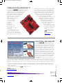
MSP430 LAUNCHPAD DEVELOPMENT KIT
Texas Instruments has announced its new MSP430
MCU Value Line LaunchPad development kit. The opensource kit includes all of the hardware and software
needed to easily launch designs based on the
MSP430 Value Line MCUs. LaunchPad supports rapid prototyping and development
by allowing developers to quickly dropin MSP430 MCUs to evaluate, program, or debug devices. This
flexibility allows developers to
remove programmed
devices to be placed
on a custom board,
or remain
plugged into
LaunchPad to
leverage on-board
buttons, LEDs, and
breakout pins for external
components.
Key features and benefits of
the development kit are a DIP
target socket, which supports up
to 20-pin devices, and pushbuttons,
LEDs, and breakout pins for external
components to allow the kit to function as a standalone system. Also featured is an integrated, USBpowered emulator that permits flash programming,
firmware debugging, and serial communication and
eliminates need for external emulator. The LaunchPad interfaces with any MSP430 Value Line MCU,
existing eZ430 target boards and MSP430
devices with Spy Bi-Wire capabilities.
To ease development, free compilers and
debuggers are available for download
including Code Composer Studio IDE
and IAR Embedded Workbench. The
kit comes with two MSP430
devices. One is preprogrammed
with demo firmware to
demonstrate the use of onchip peripherals, including
10-bit ADC, comparators,
and internal temperature
sensor.
The LaunchPad costs
$4.30 in single quantities.
Texas Instruments
www.ti.com
USER-FRIENDLY USB CONNECTOR
The new Flipper USB products are unlike conventional USB products as the patented connectors can plug into computers in either orientation.
Flipper USB has many advantages over the traditional non-“flip-able” USB devices. Flipper USB is
user-friendly and safe. With Flipper USB, it fits
into the computer port either way. The user simply plugs in a USB device without looking, trying,
thinking or guessing. It just works. This could
save the user tremendous time and frustration.
Furthermore, since Flipper is “flip-able,” the computer users will never make the mistake of pushing the device too hard in the wrong orientation,
therefore avoiding damage to the computer or
the USB device.
In addition to the above “friendly-and-safe” features, the Flipper USB offers spare/back-up connections. In case of damage to one side of the connector, the user can
simply “flip it over” and use the other side of the USB device without loss of data or connections. With all the features and
advantages, Flipper USB products won’t cost more, thanks to the advanced smart design which makes Flipper truly affordable.
UltraTek offers Flipper connectors for all types of USB-related products, such as flash disk, Wi-Fi, BlueTooth, mouse,
keyboard, camera, cables, and adapters. In addition, the Flipper adapter converts the regular, non-Flipper USB product to
a Flipper USB product.
An SMT USB-A connector costs $0.65 in quantities of 100.
UltraTek
www.flipperUSB.com
NPN
y
www.circuitcellar.com
•
CIRCUIT CELLAR®
September 2010 – Issue 242
S
npn242-new_Layout 1 8/12/2010 8:46 AM Page 9
9
npn242-new_Layout 1 8/12/2010 8:46 AM Page 10
ION AND PHOTO SMOKE-DETECTOR ICs
WITH ALARM MEMORY
The low-power RE46C162/3 and RE46C165/6/7/8
(RE46C16x) ICs are the industry’s first ion and photo smokedetector ICs to offer alarm memory. These devices make it
easy to quickly determine which detector in an interconnected
loop triggered an alarm. The ICs’ low energy use enables
smoke detectors with a battery life of 10 years, and an interconnect filter enables a connection to other devices, such as
CO detectors.
Homes often
have interconnected smoke detectors
to remotely alert
the resident about
HIGH-PERFORMANCE, FULLremote smoke
SPEED USB ISOLATOR
events. When an
The PoUSBiso is a high-performance
alarm is falsely trigUSB
isolator which provides peripheral
gered, also known
isolation
and overvoltage protection.
as “nuisance tripping,” it is difficult to determine which smoke detector set
Sometimes
USB devices may operate
off the alarm. The alarm-memory feature available on the RE46C16x ICs
at different ground potentials which
enables the detector that caused the fault to be easily identified, which greatcause ground loops, signal noise and
ly reduces costs associated with installing and troubleshooting these types of
hazardous voltages. The PoUSBiso
smoke-detector systems. A charge-dump feature allows the alarm on all
operates transparently without affectinterconnected devices to stop sooner.
ing USB transfer signals, electrically
Pricing starts at $0.71 in 10,000-unit quantities.
isolates devices from hosts, and offers
overvoltage protection up to 1,000 V.
Microchip Technology, Inc.
The isolator is rated for USB 2.0 fullwww.microchip.com
speed (12 MHz) operation and delivers up to 5 V at 400 mA to the USB
peripheral over a standard USB cable.
For devices with greater current draw,
the device offers an external power
supply connection. The PoUSBiso
operates without any software, drivers
or configuration and it is a pure plugand-play device. The PoUSBiso features a small enclosure and therefore
is very handy for any pocket. The unit
has been tested with all PoLabs products, motion devices for CNC, many
microcontroller programmers/debuggers for ARM, Atmel, PIC, SiLabs, and
many other USB devices.
PoUSBiso is available for less than
$50.
September 2010 – Issue 242
PoLabs
www.poscope.com
10
NPN
CIRCUIT CELLAR®
•
www.circuitcellar.com
11_Layout 1 8/4/2010 5:00 PM Page 1
npn242-new_Layout 1 8/12/2010 1:04 PM Page 12
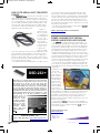
USB 2.0-TO-SERIAL UART CONVERTER
CABLES
The TTL-232RG family of USB-to-TTL serial UART converter
cables builds upon the existing FTDI family of USB-to-TTL
cables by offering new versions to support an extended variety of voltage I/O levels. The cables feature a USB-to-serial
converter PCB encapsulated within a standard type A USB
connector with a wire-ended asynchronous UART output.
The cables are aimed at providing USB connectivity within
applications with serial UART ports.
A range of
cables are available for a variety
of voltage I/O levels, including 1.8,
3.3, 5 V, or at
user-specified levels to provide
UART interfacing
to devices such
as MCUs, CPUs,
or FPGAs at a
range of voltage
levels. The cables derive power from the USB interface and
have integrated voltage regulators, removing the need for
designers to provide external power or have voltage-level
shifters on their boards. Further, the cables can be used to
provide an optional power output ranging between 1.8 and 5
V for powering external circuitry.
The cables feature the FT232R USB 2.0-to-UART convert-
OSD-232+
September 2010 – Issue 242
™
12
OSD-232+™ is a single channel on-screen composite
video character and graphic overlay device in the
form factor of a 28 pin .6” dip chip. From any
RS-232/TTL source, such as a PC or microcontroller,
control the display of 30 columns by 12 rows (NTSC)
or 15 rows (PAL) of information directly onto an incoming composite video source. Overlay characters
and graphics onto either an incoming video source or
self-generated background screen. OSD-232+™ has
256 definable 12 x 18 pixel characters. Graphic
images (such as
logos) can be imported to create
on-screen sprites.
Included with OSD232+™ is a demonstration utility,
firmware update
utility, and font
editing software.
$9900
Intuitive Circuits, LLC
Voice: (248) 588-4400 • http://www.icircuits.com
er IC with associated circuitry integrated within the cable
USB connector. The FT232R manages the complete USB
protocol within the device—meaning that no user knowledge
of USB is required. The UART interface supports data transfers at up to 3 Mbps. Using FTDI’s Virtual COM Port (VCP)
drivers, users can easily access the UART interface as a (virtual) COM port with existing software applications, removing
the need for any redesign.
All cables are FCC/CE-compliant. Pricing starts at $19.45
for the TTL-232RG-VIP-WE model.
Future Technology Devices International
www.ftdichip.com
POWER MANAGER FOR THERMAL
ENERGY-HARVESTING APPLICATIONS
The LTC3109 is a highly integrated, step-up DC/DC converter and power management IC designed to start up and
run from millivolt input voltage sources such as thermoelectric generators and thermopiles. The device’s groundbreaking and proprietary auto-polarity topology allows it to generate usable power from input voltages as low as ±30 mV,
enabling temperature differences as low as ±1°C to be harvested in lieu of traditional battery power. This makes it ideal
for energy harvesting applications in which the input voltage
polarity is unknown or is subject to reversal. Energy harvesters are well suited for applications requiring low average
power, even with periodic pulses of higher load current.
The device uses two standard compact step-up transformers to provide a complete power management solution. Its
2.2-V LDO can power an external microcontroller, and its main
output is pinselectable to one
of four (2.35,
3.3, 4.1, or 5 V)
fixed voltages to
power a sensor,
data acquisition
circuits and/or a
wireless transmitter. A second
switched output
can be enabled
by the host in
order to power devices that do not have a micropower shutdown capability. The addition of a storage capacitor provides
continuous power even when the input energy source is
unavailable or intermittent. The LTC3109’s extremely low
quiescent current (less than 7 µA) and high-efficiency
design ensure the fastest possible charge times for the output reservoir capacitor.
Pricing starts at $3.95 each for 1,000-piece quantities.
Industrial-temperature-grade versions—the LTC3109IUF and
LTC3109IGN—are also available starting at $4.65 each for
1,000-piece quantities.
Linear Technology Corp.
www.linear.com
NPN
CIRCUIT CELLAR®
•
www.circuitcellar.com
17.qxp
2/9/2010
9:56 AM
Page 1
npn242-new_Layout 1 8/12/2010 8:46 AM Page 14
LED DRIVER ICs DELIVER FLICKER-FREE
TRIAC DIMMING
The LinkSwitch-PH and LinkSwitch-PL are two new families
of TRIAC-dimmable, single-stage, power-factor-corrected LED
driver ICs targeting solid-state lighting applications.
LinkSwitch-PH (optimized for isolated systems) and
LinkSwitch-PL (optimized for non-isolated systems) deliver
flicker-free monotonic TRIAC dimming and a user experience
similar to that provided by incandescent illumination.
Both families feature integrated single-stage power factor
correction, enabling SSL luminaires to achieve a power factor
of less than 0.9. LinkSwitch-PH devices incorporate primaryside-control technology, which eliminates the optocoupler
and supporting components used in traditional isolated flyback designs. Non-isolated LinkSwitch-PL designs further
reduce component count, resulting in improved reliability
and a reduced bill of materials. Both IC families are monolithic—incorporating the controller and MOSFET onto a single silicon die—which simplifies PCB layout by minimizing component count and eliminating parasitics between the controller and
power MOSFET. These products are optimized for high efficiency in simple flyback designs and operate at input voltages up to
305 VAC, enabling the development of both single-voltage and universal-input products suitable for residential and commercial
lighting applications worldwide.
When operated within manufacturers’ temperature and drive-current guidelines, LEDs can be expected to operate for more
than 50,000 hours. LinkSwitch-PH samples are available now in a halogen-free, ROHS-compliant eSIP(R)-7C package, priced
between $1.18 and $1.71 each for 10,000-piece quantities.
Power Integrations, Inc.
www.powerint.com
September 2010 – Issue 242
NPN
14
CIRCUIT CELLAR®
•
www.circuitcellar.com
npn242-new_Layout 1 8/12/2010 8:46 AM Page 15
SUBSEA WELLBORE PRESSURE + TEMPERATURE TRANSDUCER
The Model PT36xx subsea wellbore pressure and temperature transducer delivers long-term performance in harsh
subsea oil and gas exploration environments. It has a total
error band of ±1% of full scale output and is designed for
working pressures to 15,000 psi and seawater depths to
17,000′. Both temperature and pressure sensors are located at the flush-end of the wellbore probe, a design feature
that improves dynamic response and alleviates clogging.
The PT36xx is constructed with no external load-bearing
welds thus increasing service life and improving field serviceability.
The PT36xx is constructed of Inconel and 316 stainless
steel. It can be configured as a pressure only or temperature only unit. The standard unit incorporates a 3 1/16″ API
flange, although customers can specify their flange of
choice. Probe lengths are available in lengths of 3″ to 24″.
Both probe lengths and electrical terminations are customer-specified. PT36xx is also available with dual-redundant pressure sensors for extremely demanding applications. Customers can select from numerous available electrical outputs: 4 to 20 mA, 0 to 5 VDC, 0 to 10 VDC, as well as digital outputs
including RS-232, RS-485, and CANbus. Each wellbore transducer is shipped with a multi-point calibration record that’s traceable to NIST as standard. Material traceability is also available on request. Due to various configurations and customer-specified
features, contact the factory for pricing and delivery.
Stellar Technology
www.stellartech.com
NPN
npn242-new_Layout 1 8/12/2010 8:47 AM Page 16
RESISTIVE SPLITTERS FOR RF AND
MICROWAVE APPLICATIONS
CONNECTORS ENSURE A SECURE CONNECTION WITHOUT OVERTIGHTENING
The IPS Series is a new line of wideband two-, three-, and four-way resistive
splitters. The series is designed for engineers who desire a single device that can
perform optimally over a broad range of
frequencies. The two-way (6 dB) resistive
splitter functions optimally from DC to
20 GHz with accuracy starting at ±0.5
dB, while the three-way (9.5 dB) and
four-way (12 dB) splitters function from
DC to 7 GHz with accuracy starting at ±0.7 dB. These devices are
available for surface-mount, microstrip, or wirebond implementation. Rated power is as high as 3 W. Applications for the IPS
Series resistive splitter include but are not limited to RF test and
measurement instrumentation, amplifier circuits, and coaxial
splitters.
Samples of all the IPS Series splitters are available by contacting the factory or visiting the website. IMS also offers a wide
range of high-quality thick film resistors, terminations, attenuators, couplers, thermal management devices, planar dividers,
and planar filters.
Pricing depends on configuration.
TURCK introduces the M12 true torque connectors,
which may be hand-tightened to a predefined torque, preventing over-tightening. Determining whether or not a
connector is properly secured is easy with the true
torque connector. Once the proper torque has been
achieved, the nut rotates
freely—indicated by a clear
haptic and audible signal.
The true torque connector is
compatible with all existing M12
products and can be manually
connected, with no tools
required. Because the connector cannot be over-tightened,
the integrity of the mechanics
and the o-ring connection is
maintained. These connectors
are available with 3, 4, or 5
poles, in both male and female versions, and in either
straight or right-angle configurations. Contact TURCK for
pricing.
International Manufacturing Services, Inc.
www.ims-resistors.com
TURCK
www.turck.us
September 2010 – Issue 242
NPN
16
CIRCUIT CELLAR®
•
www.circuitcellar.com
eq-242_Layout 1 8/11/2010 12:19 PM Page 17
CIRCUIT CELLAR
Test Your
Edited by David Tweed
Problem 1—In a synchronous digital transmission system such as T1 or E1, what is
the function of the framer?
Problem 2—What is the difference
between a sequential framer and a parallel
framer?
EQ
Problem 3—What measures can be taken
to make sure the framer functions reliably even in the presence of bit errors?
Problem 4—Is any of this applicable to
decoding radio time signals, such as
WWVB?
Contributed by David Tweed
What’s your EQ?—The answers are posted at
www.circuitcellar.com/eq/
September 2010 – Issue 242
You may contact the quizmasters at [email protected]
www.circuitcellar.com
•
CIRCUIT CELLAR®
17
Land_Interview_242_Layout 1 8/11/2010 12:21 PM Page 18
QUESTIONS & ANSWERS
Interdisciplinary Engineering & Research
An Interview with Bruce Land
Bruce Land is a Senior Lecturer in Electronics and Computer Engineering at Cornell University
(www.nbb.cornell.edu/neurobio/land/). This year he’s teaching two courses: one covering microcontrollers
as components in electronic designs, and one dealing with designing FPGA circuits for embedded applications. Bruce is also co-director of the Masters of Engineering Program in the Cornell School of ECE. Since
2002, seven of Bruce’s articles have appeared in Circuit Cellar. In July 2010, I interviewed Bruce about his
background, work, and many interests, which range from electronics to neurobiology to programming to
physics. — C. J. Abate, Editor-in-Chief
CJ: Please describe your background and how you ended up at
Cornell.
BRUCE: I went to Harvey Mudd College, graduated in 1968
with a degree in physics, and moved to Ithaca, New York, to
start graduate school in neurobiology doing artificial neural net
research with Frank Rosenblatt. Today, I am a senior lecturer in
the School of Electrical and Computer Engineering (ECE) at Cornell University. I teach two design courses, one using microcontrollers and C, and one using FPGAs and Verilog plus C. I also
collaborate with a couple of labs in the Department of Neurobiology and Behavior (NBB). In this role I mostly simulate neural
systems, figure out ways of visualizing biological data, and build
instrumentation.
CJ: When did you become interested in electronics and engineering? How long have you been reading Circuit Cellar?
BRUCE: I have been interested in electronics as long as I can
remember. One of my first memories is of sticking two screwdrivers in a socket, then grabbing them. What I actually remember is flying across the room backwards. By middle school I was
interested in RF and high voltage and built a Tesla coil with an
811A power triode that would light up a fluorescent light six
feet away. I got interested in Boolean algebra and computing in
high school, but did not have access to a computer until college.
I have been reading CC since 1997, but read columns by Steve
Ciarcia in Byte magazine starting in about 1979.
September 2010 – Issue 242
CJ: What about working with “embedded technologies” and
your first MCU-based design?
18
BRUCE: Starting in 1973, I used an Intel 4004 processor set. By
1977, I was using a DEC PDP-11 to control biology experiments
and record data. I bought an Apple II in 1979 and wrote 50 pages
of assembler to make an animated orbital dynamics game.
Beginning in 1986, I worked with computer graphics on supercomputers for 12 years. In 1997 I started teaching embedded
design in ECE and building instrumentation in NBB.
I built a cricket call generator for Ron Hoy at Cornell using an
Intel 4004 processor in 1973. It had a keypad, LED numeric display, and an analog sound synthesizer, all driven from 512 bytes
of ROM. The device was hand-soldered and took nine months
to build and debug. We entered test code by stepping through
memory toggling front panel switches because we could not
afford a development system.
CJ: You have an interesting background: physics, neurobiology,
graphics/animation, computer science, and ECE. What is your
main interest, and how does electrical engineering factor in?
BRUCE: Harvey Mudd College gave me an excellent math and
physics background, which I have used ever since to learn and
understand new fields. Between my junior and senior year at
HMC, I spent the summer at Ames National Lab in Ames,
Iowa, as an intern in a nuclear physics group. In Ames I had
very little to do outside of work, so I spent a lot of time in the
library, where I found a very interesting book on perceptrons
written by Frank Rosenblatt. I decided to go to graduate school
at Cornell because of that book. I worked on artificial intelligence for two years, but Frank was killed in a boating accident
in 1971. I then switched advisors and started working on the
membrane biophysics of developing muscle. The math/physics
background made this possible and interesting. The mathematical modeling for this work was done analytically, but toward
the end of my dissertation work, it became obvious that computer simulation methods were necessary for the next step. I
stayed at Cornell as a postdoc doing electrophysiology and computer simulation of nonlinear reaction-diffusion equations to
model the binding of acetylcholine (a neurotransmitter) to muscle. I became more interested in the simulation than the physiology, and when the Cornell Theory Center became one of five
supercomputer sites funded by NSF in 1985, I switched departments to start supporting high-performance scientific computing. Over the next two years, I got interested in the challenges
of converting vast numerical supercomputer output into understandable and informative graphics and ran the Cornell Theory
Center graphics group for 10 years. During that time, I started
CIRCUIT CELLAR®
•
www.circuitcellar.com
Land_Interview_242_Layout 1 8/11/2010 12:21 PM Page 19
teaching computer graphics in the Department of Computer
Science, which was great fun. The Theory Center lost federal
funding in 1997 and, by chance, I found out that Electrical and
Computer Engineering needed someone to teach embedded
design. So I applied. I really enjoy the interplay between hardware and software and watching students design interesting
devices using all the tools they have learned. The physics and
math from college, plus the one credit of FORTRAN that was
required of all freshmen, form the basis for continually re-educating myself.
choose a subject or technology on which to focus?
CJ: You were using computer modeling as early as the late
1970s for your neuromuscular studies. Was that the first time
you used computers for your academic endeavors?
CJ: Your TV oscilloscope project (Circuit Cellar 161, 2003) was
designed specifically for use in Cornell’s neurobiology labs. Is it
still in use? Any recent upgrades or redesigns?
BRUCE: I started using computers (digital and analog) academically for data reduction and modeling for physics labs in college.
The machine was an IBM 1620 with punch card input. In graduate school I started using the FOCAL language running on a
PDP-8 interactive system with teletype input for statistics. But
the first real time experimental use was hooking a PDP-11 to
my electrophysiology rig, which at the time meant writing a
device driver in assembler to run the A/D converters and building a hardware clock for the converters. This allowed me to collect hundreds of waveforms on a floppy disk in an afternoon of
recording and reduce them in a few minutes to a useful summary. The output data from the experiments was then compared to
simulations of the neurotransmitter reaction-diffusion equations
underlying the waveforms. The simulations had to be run on an
IBM mainframe and it was all we could manage to simulate a
one-dimensional diffusion system, even though we knew the
real system was probably at least 2-D. By comparing the simulated and real waveforms, we could deduce the chemistry of the
binding of the neurotransmitter to muscle.
BRUCE: There was one further design change of that system so
that it is an almost complete electrophysiology system. I never
wrote it up, but it is linked at www.nbb.cornell.edu/neurobio/
land/PROJECTS/TVnuS/index.html. I also designed some
model neurons for teaching, which I have not done much
with, at www.nbb.cornell.edu/neurobio/land/PROJECTS
/ModelCell442/index.html. All of the circuits have been used
in teaching labs, but are not currently in use.
BRUCE: As part of my Theory Center job, I had an academic
appointment in the Department of Computer Science from
1992 to 1997. This allowed me to teach computer graphics.
When the Theory Center lost federal funding in 1997, I started
teaching in Electrical and Computer Engineering, but I was
actually shared between ECE and NBB. In neurobiology, I taught
electronics and programming for biologists. I had a good feel for
how biologists think (having worked in neurobiology for 18
years previously), so I converted the hardcore math approach,
which tends to be used in engineering, into a form that was rigorous but much simpler to follow, with lots of examples based
on the needs of the research biologist. For example, it is fairly
easy to compute the length constant of a leaky cable (Lord
Kelvin did it) using calculus, but it is even easier to use high
school algebra and take the calculus-style limit at the very last
step in a way that people without very much calculus can easily
follow.
CJ: Since 2002, Circuit Cellar has published seven of your articles. With so many interests in different disciplines, how do you
www.circuitcellar.com
•
CIRCUIT CELLAR®
CJ: Circuit Cellar readers all over the world are now familiar
with your work, as well as many of the projects your students
completed in your ECE courses. During the last few years, we
published several articles about projects that began in your lab.
Examples include: “Self-Powered Solar Data Logger” (A. Krich,
Circuit Cellar 198, 2007); “RFID Security System” (C. Ross and
R. Goto,” Circuit Cellar 199, 2007); and “Keystroke Communication” (N. Paya and V. Ganesh, Circuit Cellar 227, 2009). Few
other instructors we know of have so many talented students
producing such innovative MCU-based designs. Tell us about
your design courses. Is the ultimate goal to build something?
Describe the balance between classroom lectures and actual
design time at a workbench.
BRUCE: The course ECE 4760 is a design course in which we
ask the students to use all of their engineering background to
produce interesting microcontroller-based devices. We spend
time talking about specific programming techniques, intellectual property issues, debugging, and how to decode a cryptic
datasheet. The students have an awesome theoretical background, and this course is one of several which gives them a
chance to apply their theory to practical design. The course is
primarily driven by lab exercises. There are no tests or quizzes;
rather, students are expected to show up for lab ready to perform and are graded on their performance and the resulting lab
reports. For the last five weeks of the semester, the students
have only one assignment: to design, build, demonstrate, and
document a device of their choice. The class webpage has over
350 projects. These project reports serve to set the expectation
level for grading and act as a source of code for new projects
(properly acknowledged). I am continually amazed at the creativity the students show and how hard they can work. At the
end of the semester, I encourage and help the students to
publish their work and, occasionally, to disclose a potential
September 2010 – Issue 242
CJ: In the 1990s, you taught graphics, computer programming,
and electronics courses at Cornell. How did this come about?
BRUCE: I just do whatever seems interesting at the time. I read
a lot, so some topics are based on a technique that I have read
about. Some topics arose because they seemed necessary for the
way I wanted to teach the microcontroller or FPGA course. The
video generator came about this way and so did the DSP articles. Some topics are of mathematical interest to me, and sometimes I just want to see how much performance I can squeeze
out of a small processor.
19
Land_Interview_242_Layout 1 8/11/2010 12:21 PM Page 20
invention to Cornell in order to pursue a
patent.
CJ: What do you ask of your students at
the beginning of each semester? How do
students choose designs and supplies?
BRUCE: I ask the students to be proactive and behave more like employees and
less like students. They are expected to
do the assignments without being forced
by testing to memorize details. Project
designs are specified in several steps.
Informal discussion with each student
group results in a formal project proposal,
which is reviewed by the teaching assistants and by me. We comment on the
hardware and software feasibility, lab
facilities (e.g., Does the project require a
milling machine, which we don’t have?),
and overall novelty and interest of the
project. Typically, a class of 100 students
will have about 40 to 45 different projects
carried out in groups of two or three students. Parts for the projects are scavenged, purchased, or donated. Each
group is limited to a budget of $75, but
scavenged or donated parts do not count
against the budget. I have a couple of
cabinets of random parts, which the students can use, but some purchase their
own parts, up to the limit of $75. Since
$75 is only about one-half the cost of a
textbook, I don’t believe that it represents a significant burden to students.
CJ: Tell us about your interest in
FPGAs. We’re familiar with your hybrid
computing article, and we know they
are a central topic covered in your ECE
5760 course.
BRUCE: FPGAs are great when you
need computing bandwidth or hardware
flexibility, or want to play with parallel
computing. Students can design and prototype a 32-bit microcontroller in a couple of hours using modern tools. ECE
5760 assumes that the students can program in C and design hardware in Verilog. We ask the students to combine
custom processors with special-purpose
hardware (which they design) to solve
real-time problems like video or audio
synthesis. Often, the solution will
involve parallel hardware algorithms to
Leading Embedded
Development Tools...
ZZZDUPFRPWRROV
ZZZNHLOFRP
September 2010 – Issue 242
For Microcontroller:
20
®
6RIWZDUHGHYHORSPHQWWRROVIRU$50
70
&RUWH[DQG&0&8V
5726DQGPLGGOHZDUHOLEUDULHV
'HEXJDGDSWHUVDQGHYDOXDWLRQERDUGV
For ARM Application Processors:
(FOLSVHEDVHGGHYHORSPHQWWRROVIRU/LQX[
DQG$QGURLG
6XSSRUWIRUDOO$50DSSOLFDWLRQSURFHVVRUV
+LJKSHUIRUPDQFHGHEXJDQGWUDFHDGDSWHU
1-800-348-8051
get speed. I think that training in parallel computing is essential at this time.
CJ: I’m sure many of the young engineers you work with have a decision to
make. They have a design idea, and then
they ask: Do I use microcontrollers,
FPGAs, or CPLDs? Any general advice?
BRUCE: There are many trade-offs: ease
of programming, familiarity, cost, I/O
bandwidth, fabrication, and so on. We
chat about all of these when starting a
project.
CJ: Speaking of FPGAs, you recently
informed me that you wrote some code
for computing chemical kinetics solutions on an FPGA. What exactly is
chemical kinetics, and how are you
using the FPGA?
BRUCE: Chemical reactions are processes by which chemicals are converted to
other chemicals. A huge number of such
reactions are going on in your body as
you read this. For instance, sugar is
being converted to less energetic compounds, plus high-energy ATP, a chemical which is the energy currency of the
cell. Chemical kinetics describes the
dynamics of the conversions as a rate of
conversion which depends on the concentrations of the reacting chemicals,
the temperature, the pH, and numerous
other factors. These factors are often
summarized as a “rate constant.” Traditionally, the rate equations are written
as a set of differential equations and
solved using numerical methods, such as
Runga-Kutta integration or “stiff equation” solvers. But real reactions always
occur between individual molecules,
which are not “differentially smooth,”
except in the limit of large numbers of
molecules. An alternative approach is to
solve the system by treating the rate
constant as a probability of reaction
over a short period and asking if the
number of molecules changed in the
short time step, then repeating. This
Monte Carlo approach is more time
consuming than the differential equation solution but is more accurate when
only a few molecules are reacting and
gives more information. It is possible to
parallelize the computation on the
FPGA by generating many random
CIRCUIT CELLAR®
•
www.circuitcellar.com
Land_Interview_242_Layout 1 8/11/2010 12:21 PM Page 21
numbers simultaneously. Speedups of
between 10 and 500 are possible over
the PC solution of the system.
NEED-TO-KNOW INFO
CJ: FPGA projects, programming, neuroscience, graphics, physics. Where do you
find the time for all of this tech work?
Do you have any free time?
For more information about Bruce Land’s work, the Circuit Cellar editorial
staff recommends the following content:
—
Floating Point for DSP
by Bruce Land
Circuit Cellar 235, 2010
For DSP and other fine-grained parallel operations, you need to pick a
floating-point representation and implement five basic operations. The 18bit floating point described here allows up to 70 floating-point multipliers
and around 150 floating-point adders to be placed on an FPGA. Topics:
DSP, Floating-Point Math, FPGA, Conversion, Matlab
BRUCE: I do some of the work, but a
large number of very good students do a
lot of it. I supervise about a dozen Master’s of Engineering projects and undergraduate projects each year, outside of
the two classes I teach. In my free time I
do some forestry and gardening and try
to live sustainably. We have 5.6 kW of
photovoltaic solar and 3 kW of solar hot
water collectors. We have chickens and
honey bees and grow most of our own
food.
CJ: Planning any other projects for the
near future?
BRUCE: A collaboration with the Cornell Lab of Ornithology may result in
some interesting bird-based ad hoc networks. I am working on the simulation
of toadfish swim bladder sound production to try to understand some, apparently, chaotic sounds. I am designing a
video analysis system for fish activity.
Knowledge is power. In the computer applications industry, informed engineers and programmers don’t just survive, they thrive and excel.
Go to: www.circuitcellar.com/magazine/235.html
—
Hybrid Computing on an FPGA
by Bruce Land
Circuit Cellar 208, 2007
Bruce explains how to simulate the parallel functions of an analog computer on an FPGA. Now you can harness the advantages of parallel execution and a general-purpose CPU on the same chip. Topics: FPGA, CPU,
Parallel Execution, Analog Computer, VHDL
Go to: www.circuitcellar.com/magazine/208.html
CJ: You interact with up-and-coming
electrical engineers, embedded designers, computer scientists, and programmers on a daily basis. What would you
say are the “hot” topics exciting this
new generation of engineers?
CJ: What is the biggest “growth area”
for the embedded industry?
BRUCE: Instrumentation: energy control, biomedical measurements. Geriatric applications for us baby boomers:
smart walkers, web-attached pill dispensers, etc. And, of course, mobile
devices. I
www.circuitcellar.com
•
CIRCUIT CELLAR®
September 2010 – Issue 242
BRUCE: Energy (control, production,
and storage); biomedical instrumentation, game design; robotics; parallel or
multicore, multithread computing; photonics and optical techniques in computing; and human-computer interaction.
21
2109006_Novacek_Layout 1 8/12/2010 1:06 PM Page 22
T
HE CONSUMMATE ENGINEER
by George Novacek (Canada)
Is the Door Closed?
Why Every Safety-Critical Decision Matters
Part of developing a “robust” system involves ensuring your design is safe
and secure. Whether you’re building a small embedded app or a complicated
door-opening control system for a plane’s landing gear bay, you must
protect both your design and the end users by choosing the proper parts
and design techniques.
September 2010 – Issue 242
I
22
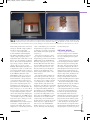
t may be very important to know if the
door is closed. The answer is obtained by
acquiring data reflecting the door’s status.
Every control system needs data to act upon.
In embedded controllers, most of the time, the
data is provided by various detectors and sensors. Whether the controller itself is analog or
digital is a secondary matter. The primary consideration is the type of sensor and its characteristics in terms of the operating environment. Let’s consider an example.
There are numerous mechanical devices on
an aircraft whose configuration you must
know at any given time. Doors are such
devices: landing gear bay doors, passenger
doors, and so on. You must also know the configuration of the up and down locks for the
landing gear. To obtain their status, you must
use some kind of a sensor—a limit switch, for
example—to detect the position of the device
you’re monitoring. Then, the resulting signal
is acquired by the controller, digitized (if necessary), and processed. The trick is to deliver
that important signal to the controller consistently and reliably.
Mechanical limit switches—such as micro
switches—are rarely seen on aircraft. They are
not very reliable in the harsh aerospace environment, and their maintenance by replacement is costly. Instead, proximity detectors are
commonly used to detect the positions of moving mechanical parts. This column is not a
proximity detection tutorial, but you need to
understand the technical basics of proximity
detection to follow my example. So, I’ll only
briefly describe the principle of inductive proximity detectors as found in many real-world
applications.
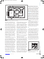
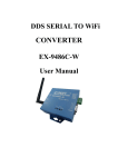
Figure 1 is a block diagram of a typical proximity detector. A proximity detector consists
of an oscillator, a part of which is a sensing
coil. As the metallic target attached to a
mechanical part being monitored moves
toward the coil, the coil impedance changes,
and this results in a voltage or current change.
That voltage or current change is decoded and
the output driver is energized accordingly. The
device is usually powered by two wires, and
the current driving the device is monitored by
the controller. This current is divided into five
distinctive bands. Target far is usually a lowcurrent region. Target near is usually a highercurrent region. Both appear in Figure 1. Currents less than the minimum target far, higher
than target near, or between the targets (noted
in Figure 1) mean that the detector is not
operating correctly and its data should be
rejected. This way a proximity detector not
only detects the position of the monitored
component, but also indicates whether the
device is functioning correctly—a crucial
characteristic in safety-critical systems.
SWITCH OR SENSOR?
The proximity detectors come in two basic
flavors. A “proximity switch” contains all the
components in Figure 1 in one tiny package,
interfacing with the controller with a twisted
CIRCUIT CELLAR®
•
www.circuitcellar.com
2109006_Novacek_Layout 1 8/11/2010 12:25 PM Page 23
wire pair. The controller needs only to
+
Fault
monitor the current to derive the status. A “proximity sensor,” on the other
Target near
Oscillator
hand, is merely the sensing coil, while
Prox
current
Sensing
vs. target
Fault
coil
the associated interface electronics are
position
an integral part of the controller.
Target far
Output driver
So which one of the two functionally
Amplifier and
Target
Fault
comparator
–
identical devices should we use? The
switch or the sensor? It depends. Make
Figure 1—This is a typical proximity detector.
a wrong choice and you may regret it.
Proximity switches are simple to use
and to design around. Plus, the total cost of implementahowever, know that the essential part of engineering is a
tion is low. Their interface bandwidth and impedance to
trade-off. Performance, reliability, operating environment,
the controller are low, so it’s easy to protect their signal
maintenance, cost, and time to market all play a role. Fad
from transients, electromagnetic interference (EMI), and all
architectures and elegant “gee-whiz” designs mean little if
the nasty disturbances bouncing around the aircraft. Propthey’re not 100% satisfactory. There is no universal best
erly constructed, a proximity switch generates no measurasolution, not even for functionally identical tasks like monble interference of its own.
itoring a status of a door. A good engineer keeps his options
The proximity sensor interface, on the other hand, is
open and is not afraid to use even old, time-tested design
complicated. The sensing coil, far removed from the intersolutions if they best satisfy the issues at hand. Then and
face circuitry, must be connected by a shielded cable. It can
only then can he deliver optimal, robust designs. I
generate unwanted emissions, the small reactance changes
of the coil due to the target movement may be obliterated
George Novacek ([email protected]) is a professional
by noise and external interference. The system integration
engineer with a degree in cybernetics and closed-loop conis time consuming and requires experience.
trol. Now retired, he was most recently president of a
So, why would you even bother with the sensor? The
multinational manufacturer for embedded control systems
proximity sensor has some important redeeming qualities.
for aerospace applications in Canada. George wrote 26 feaOnly the sensing coil is exposed to the elements and not
ture articles for Circuit Cellar between 1999 and 2004.
much bad can happen to a rugged coil in the tough environment of landing gear, inside a jet engine or a space shuttle.
Heat it up to nearly a melting point, freeze it to cosmic cold,
immerse it in water, shake it, hit it with a hammer—the coil
Knowledge is power. In the computer applications
will continue to work reliably. Try doing the same to the
industry, informed engineers and programmers
proximity switch! If there is a chance that the operating
don’t just survive, they thrive and excel.
environment could unexpectedly exceed the relatively mild
To learn more about George Novacek’s design tips
operating conditions of the proximity switch, you may be in
and projects, the Circuit Cellar editorial staff recfor a costly controller redesign. A proximity switch on a
ommends the following:
passenger door in an aircraft’s inhabited environment will
—
work just fine, but on control surfaces I’d want to see proxFault-Tolerant Electronic Systems
imity sensors. I want to know that the thrust reverser
by George Novacek
doors, for example, are really retracted. Lives may depend
Circuit Cellar 162, 2004
on knowing this.
All electronic systems fail. So, to be a successful designer of embedded systems, you must preSystem design and its reliable data acquisition from its
pare for system failures and glitches. Topics: Fault
peripheral components require not just a thorough knowlTolerance, Failure, Built-in Test, Redundancy
edge of the system and its operating environment, but also
an understanding of the internal characteristics of the
Go to: www.circuitcellar.com/magazine/162toc.htm
devices used to acquire the data. I used a simple, 1-data-bit
—
example to illustrate the point, but the same consideration
Time-Triggered Technology
by George Novacek
must be given to the selection of all systems’ peripheral
Circuit Cellar 155, 2003
devices.
Clearly, the older communications protocols
used by the aerospace industry are becoming
FUNCTIONALITY MATTERS
increasingly expensive to implement. But, as
It is easy to get carried away by the capabilities and
George explains, TTP technology could change
the game. Topics: Time-Triggered Protocol, Data
sophistication of new technology, such as smart sensors,
Bus, Frame
smart actuators, high-level languages, or distributed processing. One can declare a holy war on anything other than
the most advanced methods, insisting that those and only
those find their way into his design. Experienced engineers,
www.circuitcellar.com
•
CIRCUIT CELLAR®
Go to: www.circuitcellar.com/magazine/155toc.htm
September 2010 – Issue 242
NEED-TO-KNOW INFO
23
2_Layout 1 5/12/2010 7:18 AM Page 1
2_Layout 1 5/12/2010 7:18 AM Page 2
F EATURE
2109014_Ludington_Layout 1 8/11/2010 1:07 PM Page 26
ARTICLE
by David Ludington (USA)
Precision Temperature
Control Circuitry
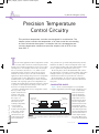
This precision temperature controller was designed for a calorimeter. The
unique system controls the temperature of an outer metal box surrounding
an inner calorimeter base plate. It maintains the box’s temperature and
controls temperature variations around the setpoint with an STD of less
than 0.01°C.
September 2010 – Issue 242
T
26
here are many applications where temperature control were generated. To get initial temperature data, the first
is needed, such as home air conditioning and indushardware was built to control a metal plate inside a pastrial processes. Of these applications, most do not require
sive metal box. Results from testing this hardware will be
much precision. For example, in the home, the temperaused to optimize the temperature control loop.
ture is controlled to about 0.5° to 1°C, while in some
In the next phase, the modified hardware will control
industrial products electronic components are held to
the temperature of a metal box. This probably will require
within 0.1°C. However, there are some measurement
multiple control loops since there is not good thermal
applications where much greater precision of temperature
contact between the box top and the rest of the box.
is required. One of these applications is a calorimeter
In the third phase, an even more precise temperature
which measures very small changes in heat to determine
control circuit will be needed to control the calorimeter
material or biological properties. The temperature surbase plate.
rounding the measurement cells must be held as constant
as possible so that temperature changes in the environCALORIMETER BASICS
ment do not corrupt the measurements.
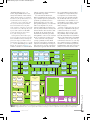
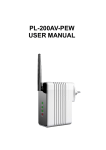
Figure 1 shows a system diagram for an isothermal
In order to understand the level of temperature control
(constant temperature) calorimeter. The calorimeter conthat is possible, a mulsists of a metal base
tiphase study has been
plate at a fixed conMetal box
initiated. This study
trolled temperature
will seek to optimize
with two thermopile
the design of a
temperature sensors.
Measurement
Reference
sample holder
sample holder
calorimeter and will
One thermopile measbuild and test the
ures the temperature
resulting temperature
difference between the
Thermopile
Thermopile
control circuits.
measurement sample
This article will
and the base plate. The
Metal base plate
describe the first phase
other thermopile measof the study. A funcures the temperature difThermal insulator
Temperature sensor
tional design of the
ference between the refcalorimeter was pererence sample and the
Figure 1—The heart of the calorimeter. Each thermopile outputs a voltage proformed and performbase plate. When a reacportional to the temperature difference between the top and bottom plates of
the thermopile.
ance requirements
tion in the measurement
CIRCUIT CELLAR®
•
www.circuitcellar.com
2109014_Ludington_Layout 1 8/11/2010 1:07 PM Page 27
Temperature
sensor
LM35
Dual amplifier
MCP607
Base plate
temperature
Bias voltage
MOSFET
Drivers
TC4427
STP16NF06 FET
and resistive
heaters
PI Control loop
algorithm
A/D
Converter
Microcontroller
dsPIC30F2011
PWM D/A
Converters
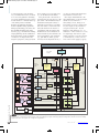
Figure 2—The control loop functional design. The dsPIC30F microcontroller has a 12-bit ADC
and 16-bit PWM outputs. The thermal resistance and heat capacity of the heaters and plate
filter the digital PWM signals to provide smooth temperature control of the plate.
sample results in a gain or loss of
heat, the temperature of the sample
is raised or lowered relative to the
base plate temperature, and the thermopile generates a voltage signal that
measures that difference. This is the
signal you want. However, if the base
plate temperature itself changes with
time for any reason, this variation
also becomes part of the measurement channel signal and cannot be
separated from the sample signal.
The reference sample does not have
internal heat generation. It has a zero
output signal except for what’s
caused by temperature variations of
the base plate. Thus, the signal from
the reference channel signal can be
used to provide compensation for the
measurement sample by subtracting
the reference signal from the measurement signal. This reduces the
effect of base plate temperature variations on the measurement sample
signal. Of course, this only works for
temperature variations that are common to both reference and measurement signals.
The thermopile temperature sensors are very sensitive and need the
best low-noise amplifiers to measure
the small voltage signals caused by
sample temperature changes. For
low-frequency bandwidths (time constant of 5 s), the voltage noise of
these amplifiers can be reduced to
approximately 1-nV RMS. This level
of voltage noise corresponds to a temperature noise from the thermopiles
of less than one-millionth of a degree
Celsius or 1 µK. (The Celsius and
Kelvin temperature scales are the
same except for an offset.)
Several things are required to preserve this level of sensitivity. First,
care must be taken to minimize variations in the base plate temperature
caused by external (to the calorimeter) environmental temperatures
changes. In addition, care must be
taken to ensure that any such
changes equally affect both the measurement and reference samples so
that the measurement signal can be
compensated by the reference signal.
The isolation of the base plate is
helped by putting a thermally conducting
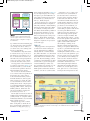
Figure 3—This is my generic controller design. The LM35 temperature sensor shown will be used to control the surrounding box temperature.
This same controller will be used with a thermistor or RTD temperature sensor to control the base plate temperature.
www.circuitcellar.com
•
CIRCUIT CELLAR®
September 2010 – Issue 242
Voltage
regulator
TC1262
27
2109014_Ludington_Layout 1 8/12/2010 1:17 PM Page 28
Microcontroller initialization
Wait for Timer2 interrupt
A/D Conversion
Convert voltage to temperature
Update control loop
PWM D/A Conversion of control
loop output
Figure 4—Software block diagram
metal box around the calorimeter
that keeps the base plate’s temperature more uniform by slowing the
response to external temperature
changes. Further reduction of external temperature changes is possible
if an active control loop also controls the metal box’s temperature.
There is never perfect matching
between the reference and measurement signals, so the loop that controls the base plate temperature
must itself be very low noise so that
reference compensation of the measurement signal will be effective. The
desired goal would be for the temperature noise resulting from all
sources—external temperature variations, the metal box control loop,
and the base plate control loop—to
be equal to or less than the temperature noise of the thermopile readout
amplifier.
September 2010 – Issue 242
TEMP CONTROL ANALYSIS
28
Say you want to reduce temperature variations to less than the thermopile sensor temperature noise of
about 1 µK. At what resolution must
the base plate temperature be held to
meet that goal?
The reference compensation of the
measurement signal certainly helps,
but it cannot provide all of the needed rejection. If all of the elements
(thermopiles, sample holders, and
samples) were fixed, calibration runs
could match the sample and reference channels very well. However,
amplifier gains and delays cannot be
matched perfectly. In addition, the
amount of material in the measurement sample and reference sample
certainly varies from run to run. The
resulting difference in heat capacity
in the two channels causes the
measurement and reference signals
to respond differently to variations
in the base plate temperature.
Matching between reference and
measurement channels of 10%
should be fairly easy to achieve.
However, matching of 1% or better
is much harder. Thus, if you use reference and measurement samplematching of 1% as a practical limit,
the maximum rejection of base plate
temperature variations through reference compensation will be limited
to 100 to 1. This requires the temperature variations of the base plate
to be held to less than 100 µK to
meet the desired goal of temperature
noise less than 1 µK.
If the room temperature varies
several degrees Celsius and base
plate temperature variation is to be
held to less than 100 µK, the
required reduction of room temperature variations is over 10,000 to 1.
This is quite difficult to do with one
temperature control loop. A better
solution would be to control a metal
box surrounding the base plate with
a separate control loop to reduce the
temperature variation suppression
requirements of the inner base plate
control loop. If the outer metal box
temperature variation can be maintained at less than 0.01°C, the corresponding temperature rejection
requirements on the inner base plate
control loop are greatly reduced and
simplify the base plate control loop
design.
Holding the base plate temperature variations to less than 100 µK
also requires that the temperature
noise of the sensor temperature
itself to be less than 100 µK. (The
specific requirement depends on
control loop dynamics.) A conservative design would be for the noise of
Listing 1—A straightforward dsPIC30F embedded C program. By using Timer2 for both
the PWM and timing delay, there were plenty of clock cycles available to put all of the
processing in the interrupt routine in a linear sequence.
#include "p30F2011.h"
_FWDT(WDT_OFF);
// Watchdog timer off
_FOSC(CSW_FSCM_OFF & FRC_PLL4); // Select internal FRC clock
// and no clock switching
#define
#define
#define
#define
TEMPSETPOINT 30.0
VOLTAGEBIAS 0.299 //actual measured bias
TEMPBIAS
30.0
GAIN
12.546
unsigned int adcvalue, pwm;
double
fadcvalue;
double
temp, tempdiff, tempsum;
double
loopoutput;
int main(void)
{
// ************************* Start of Initialization
ADCON1 = 0x0000;
ADCON2 = 0x0000;
ADCON3 = 0x0004;
ADCHS = 0x0002;
ADPCFG = 0xFFFB;
ADCSSL = 0x0000;
ADCON1bits.ADON = 1;
ADCON1bits.SAMP = 1;
IFS0bits.T1IF = 0;
IEC0bits.T1IE = 1;
OC1CON = 0X0000;
// clr interrupt flag
// set interrupt enable bit
(Continued on p. 30)
CIRCUIT CELLAR®
•
www.circuitcellar.com
29_Layout 1 8/4/2010 4:49 PM Page 1
Vinculum VNC2
SPEED.
FLEXIBILITY.
A programmable system-on-chip
PERFORMANCE. USB 2.0 Host / Slave controller
- Dual channel USB 2.0 interface, handles all USB host
and data transfer functions in single IC.
- On-chip 16-bit Harvard architecture MCU core with
256 Kbyte Flash and 16kbyte RAM.
- External UART, FIFO, SPI Slave, SPI Master, GPIO and
PWM interfaces.
- Vinculum-II software development tools available
for user application development.
- Multiple package size options including VNC1L
backwards compatible package option.
- Targeted for range of USB applications, from portable
media devices and cell phones to industrial and
automotive applications.
Vinculum-II evaluation modules
- V2DIP1/2 - Miniature VNC2 Development Module
with Single or Dual USB Connectors
- V2-EVAL - Complete Evaluation & Development
Kit for VNC2
- VNC2 Debug Module
USB MADE EASY
www.ftdichip.com
2109014_Ludington_Layout 1 8/11/2010 1:07 PM Page 30
the temperature sensor to be a factor
of two better than the control loop.
This is probably better performance
than can be expected from semiconductor temperature sensors and will
likely require a lower-noise thermistor or a resistance temperature
device (RTD) for base plate temperature control. However, for the control of the box temperature, less temperature resolution is needed, and a
semiconductor temperature sensor is
a good choice.
Thus, the overall design is a twolevel control loop solution that
reduces temperature variations at the
output of the measurement channel
to less than the residual temperature
noise of the thermopile temperature
sensors. This two-level control system consists of a control loop for the
outer metal box and a control loop
for the inner base plate.
Listing 1—Continued from p. 28
OC1RS = 0X08FF;
OC1R
= 0X00FF;
OC1CON = 0X000E;
OC2CON
OC2RS
OC2R
OC2CON
September 2010 – Issue 242
30
0X0000;
0X08FF;
0X00FF;
0X0006;
TMR2 = 0;
TMR3 = 0;
PR2 = 0x0FFF;
PR3 = 999;
T2CON = 0x8000;
T3CON = 0x8000;
OC1RS
= 60;
tempsum = 3.0;
// *************************
End of Initialization
while(1)
{
CONTROLLER DESIGN
Figure 2 is a functional block diagram of the precision temperature
controller. The controller design
includes a National Semiconductor
LM35 temperature sensor to measure
the metal box’s temperature. The
LM35 datasheet doesn’t have a specification on the sensor noise voltage,
but it has a graph of noise voltage
data above 10 Hz. Extrapolating this
data below 1 Hz gives an estimated
noise of 5-µV RMS.
A Microchip Technology MCP607
dual op-amp amplifies the temperature sensor’s voltage output and
buffers an offset compensation voltage. Gain is needed to better match
the sensor noise to the resolution of
the ADC inside the Microchip Technology dsPIC30F2011 microcontroller. After A/D conversion, the
digital number representing the sensor voltage is converted into an
equivalent temperature and used to
update the proportional/integral (PI)
control loop.
Two PWM DAC outputs are sent
to a Microchip Technology dualTC4427 MOSFET driver. One of the
TC4427 outputs drives an STMicroelectronics STP16NF06 MOSFET and
switches a voltage to the resistive
heater. The other TC4427 output is
=
=
=
=
}
}
return 0;
// Interrupt routine
void __attribute__((interrupt)) _T1Interrupt(void)
{
ADCON1bits.SAMP = 0;
while(!ADCON1bits.DONE)
adcvalue = ADCBUF0;
fadcvalue = (double)adcvalue/4096*5; //12 bit A/D
// 5 volt range
temp = 100*((fadcvalue - VOLTAGEBIAS)/GAIN) + TEMPBIAS;
tempdiff = TEMPSETPOINT - temp;
tempsum = tempsum + 0.00005*tempdiff;
if(tempsum < 0.0) tempsum = 0.0;
if(tempsum > 4.98) tempsum = 4.98;
loopoutput = tempdiff + tempsum;
if(loopoutput < 0.0) loopoutput = 0.0;
if(loopoutput > 4.98) loopoutput = 4.98;
pwm = (unsigned int)(loopoutput/5.0*65536.0); //5 volt range
//16 bit PWM
OC1RS = 60;
OC2RS = pwm;
ADCON1bits.SAMP = 1;
IFS0bits.T1IF = 0;
// clear interrupt flag
}
CIRCUIT CELLAR®
•
www.circuitcellar.com
2109014_Ludington_Layout 1 8/11/2010 1:07 PM Page 31
a)
b)
Photo 1a—The test setup for the initial evaluation of circuit performance and the effects of ambient temperature changes. Results show that
passive (no temperature control) enclosures are not enough to prevent temperature artifacts. b—An expanded view of the control circuits and
controlled plate. The LM35 temperature sensor (TO-220 package) is shown at the bottom of the PCB and the 10.1-Ω resistors are to the left.
www.circuitcellar.com
•
CIRCUIT CELLAR®
a rate of 100 samples per second. The
unsigned integer output of the ADC
is changed to a floating-point temperature variable and used to update the
control loop.
After the processing, the control
loop output is converted back to an
unsigned integer and sent to the OC2
PWM module in the dsPIC30F2011.
The OC2 output (pin 15) goes to the
TC2247 FET driver that then drives
the power FET Q1 and controls the
power to the heater resistors. The
amount of heater power dissipated
depends on the magnitude of the
heater voltage and the value of the
heater resistors.
The TC1262 voltage regulator provides stable power for all of the circuits. Although the TC1262 output is
not exactly 5 V, it is nearly constant
over temperature for small current
outputs which is important in this
application. The difference in TC1262
output voltage from part to part can
be compensated during calibration
programming of the dsPIC30F2011.
The unsigned integer constant used
to generate the temperature sensor
bias voltage from PWM OC1 is calculated based on the actual TC1262
output voltage on a board. Resistor
R3 and capacitor C3 charge up slowly
when the power is applied and provide a reset for the dsPIC30F2011.
Finally, capacitors C1, C2, C4, C6,
C7, C8, and C9 provide decoupling
for the board power.
SOFTWARE DESIGN
Figure 4 depicts the software.
Except for microprocessor initialization, the program remains in an endless loop controlling the base plate’s
temperature.
A pass through the loop is initiated
by an interrupt generated by Timer2.
At the interrupt, the following tasks
take place. First, the analog temperature signal is sampled by the 12-bit
ADC and placed in a buffer. Next, the
sampled voltage is changed into an
equivalent temperature by subtracting
off the voltage offset, dividing by the
amplifier gain, multiplying by the
voltage-to-temperature conversion
constant and adding back the temperature represented by the bias voltage.
The measured temperature is then
subtracted from the setpoint temperature and the difference is used to
update the PI control loop. A fraction
of the temperature difference is added
to the previous integral value and
becomes the present integral value.
The temperature difference is also
multiplied by a gain and becomes the
proportional term. The integral and
proportional term are added together
to become the PI loop output. As part
of this calculation, the integral variable and the PI loop output are maintained within a maximum limit. If the
integral signal is not limited, it grows
September 2010 – Issue 242
filtered and generates the sensor bias
voltage. A TC1262 voltage regulator
provides power for the board.
Figure 3 is the temperature controller’s hardware circuit diagram.
The LM35 temperature sensor (U1)
output voltage is proportional to
temperature with a scale factor of 10
mV per 1°C. For example, a temperature of 30°C results in the LM35 having a voltage output of 300 mV. The
output of U1 goes to pin 3 of the
MCP607 dual amplifier (U2) where it
is amplified by a gain of 12.546 set by
resistors R1 and R2. A bias voltage of
0.3 V (equivalent to 30°C) is generated
by the PWM module OC1 in the
dsPIC30F2011. This goes to pin 4 of
the TC4427 driver, which switches
within millivolts of the ground and
+5 V rails. The driver output is lowpass-filtered to reduce the voltage ripple by resistor R6 and capacitor C5
and applied to the input (pin 5) of a
unity gain buffer in the MCP607. The
buffer output goes to one end of R2 as
the bias voltage. The bias voltage and
corresponding temperature setpoint
can be easily changed by changing the
number loaded into the PWM register.
The amplified output of the temperature sensor (pin 1 of U2) goes to the
analog input (AN2) on the
dsPIC30F2011 microcontroller and is
converted to a digital signal by the
internal 12-bit ADC. The converter
sample rate is controlled by Timer2 at
31
2109014_Ludington_Layout 1 8/11/2010 1:07 PM Page 32
to a large value during the ramp from
room temperature to 30°C and greatly
extends the time until the loop settles. If the PI loop output is not limited, it may exceed the range of the
PWM DAC.
Finally, the PI loop output is sent to
one of the pulse-width modulation
(PWM) modules of the microcontroller to generate the drive for the
heater. The software then waits for
the next Timer2 interrupt and the
repeats the process.
SOFTWARE CODING
Figure 5—A performance evaluation of about 8 h in duration. The starting temperature at
time = 0 was lower than the 28.5ºC shown, but because of the circuit gain, the input to the
ADC was saturated until the temperature moved closer to the 30ºC set point.
scope. The first part of the main program is the initialization of the modules in the microcontroller including
the ADC, interrupt controller, two
timers, and the two PWM modules.
The various register values for the
modules are defined in the dsPIC30F
family reference manual. Finally, the
tempsum variable is initialized to provide heater voltage at startup. The
remainder of the main program is a
continuously running while loop that
provides the delay between Timer2
interrupts and gives a sampling rate of
about 100 Hz.
The interrupt routine contains all
of the processing for the control loop.
When the Timer2 counter reaches its
maximum value, an interrupt is generated, the interrupt flag is set, and
September 2010 – Issue 242
Listing 1 shows the C code programmed into the dsPIC30F2011. The
first line is the “include” file that has
definitions and macros that pertain
specifically to the dsPIC30F2011. Two
macros help initialize the microcontroller. The watchdog timer (WDT) is
turned off and an internal oscillator
(FRC) with a 4× PLL is selected and
clock switching is turned off. Next
are a group of statements that define
constants used in the calculations and
the variables which are global in
32
CIRCUIT CELLAR®
•
www.circuitcellar.com
2109014_Ludington_Layout 1 8/11/2010 1:07 PM Page 33
interrupt routine ends. The while
loop then resumes and waits for the
next Timer2 interrupt.
CONTROL LOOP TESTING
the interrupt routine starts. The first
statement in the interrupt routine
resets the interrupt flag for the next
cycle.
The sampling of the ADC occurs when
the “sample bit” (ADCON1bits.SAMP)
goes low. The output of the ADC (a
12-bit number) is stored in the lower
bits of a 16-bit register (ADCBUF0). A
while loop waits for the conversion
process to be completed. Then the
value in ADCBUF0 is read into the
unsigned integer variable (adcvalue),
converted into a floating-point variable
(fadcvalue), and scaled by the 5-V ADC
input range.
Next, the floating-point voltage
(fadcvalue) is converted into a temperature by subtracting off the bias
voltage, dividing by the amplifier
gain, and adding back a temperature
equivalent to the bias voltage. The
multiplication factor of 100 occurs
because the scale factor of the LM35
temperature sensor is 10 mV per 1°C
and the temperature variable (temp)
is in volts per 1°C.
The temperature reading is then subtracted from the desired control temperature setpoint and used to update
the control loop. The integral term of
the PI control loop is tempsum and its
present value is the previous value of
tempsum plus an update, which is a
fraction of the present temperature
difference (tempdiff).
The loop output variable
(loopoutput) is the sum of the integral term and the proportional term
(a fraction of tempdiff). Constraints
are placed on the integral term and
loop output so that the integral term
www.circuitcellar.com
•
CIRCUIT CELLAR®
does not get too large at startup and
the loop output stays within the
PWM D/A range. The loop output is
converted back to an unsigned integer (pwm) and sent to the OC2 PWM
module for controlling the temperature. The OC1 PWM module generates the bias voltage, which is subtracted from the temperature sensor
output. Finally, the ADC is switched
to the acquisition mode
(ADCON1bits.SAMP = 1) and the
September 2010 – Issue 242
Figure 6—Notice the temperature scale. Each division is 5 mK. When the box temperature is
controlled, I expect the temperature artifacts to be eliminated along with the slow drift
shown from 5,000 to 10,000 s.
Photo 1 shows the hardware used
to get the initial temperature data. It
shows the PCB fabricated from the
schematic (see Figure 3) and the
setup used to test the controller’s
temperature performance. The PCB
is a 2.5″ × 3.8″ double-sided board
fabricated at ExpressPCB. The connectors at the top of the board bring
in power for the board and the heater
resistors. The connector at the top
left connects the resistors to the driver FET.
The connector at the bottom is J3,
which connects the amplified sensor
voltage to an external ADC. The converter is needed because the
dsPIC30F2011 on the processor board
does not communicate directly with
the computer. Thus, some other
means must be provided to determine control loop performance.
The analog voltage at J3 can be
33
2109014_Ludington_Layout 1 8/11/2010 1:07 PM Page 34
measured with either a high-resolution DC voltmeter or a
data acquisition system. In these first tests, the control
loop was monitored with a Symmetric Research PAR1CH
24-bit ADC. The voltage data acquired by the ADC is filtered and stored in a file. After data collection is finished,
the data is entered into an Excel spreadsheet for evaluation and plotting.
In this case, a 0.125″ × 6″ × 12″ aluminum plate’s temperature is being controlled. The PCB, LM35 temperature
sensor, and 10.1-Ω resistors are bolted to the plate. The
plate is inside a cardboard box placed inside a steel NEMA
box.
After short data runs to perform circuit debugging and
loop filter tuning, several longer data runs were made to
demonstrate the temperature performance of the control
loop. Figure 5 shows the temperature of the metal plate
being controlled. The plot shows the typical settling
response of an under-damped control loop. The amount of
overshoot shown here can be reduced by lowering the loop
gain with probably some increase in settling time.
Figure 6 shows an expanded temperature scale version of
the plot in Figure 5. At this scale, you can see a number of
features that are hidden in Figure 5. You can clearly see
the residual temperature noise. In addition, some temperature artifacts that are above the temperature noise floor
are also visible.
The STD of the noise between 5,500 and 16,500 s is 0.66 mK
and even lower noise between 10,000 s and 16,500 s is
0.35 mK. The temperature artifacts after 16,500 s are related to HVAC cycling. The data in Figure 5 and Figure 6 was
collected overnight. From the beginning of the data collection to 16,500 s, the temperature slowly cooled with the
thermostat reduced to 60°F. Toward the end of the data
collection, the thermostat was raised to 65°F. This certainly demonstrates the need for controlling the temperature
of the metal box surrounding the base plate to reduce the
effects of ambient temperature changes.
September 2010 – Issue 242
PHASE 2
34
Figure 5 and Figure 6 show that the control loop is holding the temperature of the metal plate around the desired
set point of 30°C with the best temperature variations less
than 0.001°C. This level of temperature control, when
implemented on the metal box surrounding the calorimeter
base plate, gives the base plate control loop a stable temperature environment for operation. The data also shows
that controlling a metal box surrounding the base plate is
definitely needed to reduce the load on the base plate control loop.
The data also shows that semiconductor temperature
sensors do not have low enough noise to meet the temperature control requirements for the calorimeter base plate. In
the future, I’ll explore the temperature performance of
thermistors and RDTs. However, the testing of these sensors probably won’t show improved performance unless the
testing is done within a controlled metal box.
Finally, I’ll use the semiconductor sensor just tested to
control the metal box temperature. The TO-220 package
can be easily bolted to the box. One question to be
answered is whether the box temperature can be adequately maintained with a bare metal box or whether insulation
surrounding the box is needed to slow the effect of the
temperature changes in the environment. I
David Ludington ([email protected]) is a retired
electrical engineer with experience in low-noise analog design
and infrared system design. He earned a BSEE at Michigan
State University and an MSEE at Syracuse University.
PROJECT FILES
To download the code, go to ftp://ftp.circuitcellar.com/
pub/Circuit_Cellar/2010/242.
SOURCES
dsPIC30F2011 microcontroller and MCP607 op-amp
Microchip Technology, Inc. | www.microchip.com
LM35 Temperature sensor
National Semiconductor | www.national.com
STP16NF06 MOSFET
STMicroelectronics | www.st.com
PAR1CH 24-bit ADC
Symmetric Research | www.symres.com
NEED-TO-KNOW INFO
Knowledge is power. In the computer applications
industry, informed engineers and programmers don’t
just survive, they thrive and excel.
For more need-to-know information about topics covered in David Ludington’s Issue 242 article, the Circuit
Cellar editorial staff recommends the following content:
—
Temperature Calibration System
By Brian Millier
Circuit Cellar 202, 2007
Brian’s portable temperature meter has a PID
controller and a user interface for entering a setpoint. It plugs into a separate calibrator unit, which
generates stable temperatures for sensor calibration
purposes. Topics: Temperature, Calibrator, RTD,
Thermocouple
Go to: www.circuitcellar.com/magazine/202.html
—
Multi-Input Temperature Logger
By Nial Stewart
Circuit Cellar 198, 2007
Nial designed an FPGA-based multi-input temperature logger. It includes an innovative USB
interface. Topics: Temperature, Logger, FPGA, USB
Go to: www.circuitcellar.com/magazine/198toc.htm
CIRCUIT CELLAR®
•
www.circuitcellar.com
10_Layout 1 5/12/2010 8:32 AM Page 1
F EATURE
2109015_Rowe_Layout 1 8/11/2010 1:03 PM Page 36
ARTICLE
by David Rowe (Australia)
Mesh Telephony System
The Mesh Potato Project from an Embedded Designer’s POV
You might have heard about The Mesh Potato, a key component in The
Village Telco project aimed at giving people in developing countries a
low-cost alternative to mobile phones. This article focuses on the
“embedded development” aspects of the project, such as the Wi-Fi SoC
and interface design.
I
am part of a team developing an open hardware
mesh router with telephony called the Mesh Potato.
Based on an Atheros Wi-Fi system on a chip (SoC), the Mesh
Potato is a key component in the Village Telco—a project to
give people in the developing world a low-cost alternative to
mobile phones. The Mesh Potato is an 802.11bg router that
you can plug a telephone into. It combines the functions of
an Analog Telephony Adapter (ATA) and Wi-Fi router, and it
includes BATMAN software for mesh routing and runs
Asterisk for VoIP. In this article, I’ll describe the Mesh Potato
design (see Photo 1).
turn a router SoC with minimal interfaces into a mesh Wi-Fi
telephony device.
Consider a simple Mesh Potato mesh network (see Figure 1).
In mesh networks, each node relays messages for adjacent
nodes. This extends the range of effective IP communications
compared to infrastructure-mode networks that use a central
access point. Mesh Potato A can’t communicate directly with
the gateway because it is out of range. However, nodes B and
C can be used to relay packets for A. The BATMAN mesh
routing algorithm used for the Village Telco automatically
September 2010 – Issue 242
MESH NETWORKING
36
The Mesh Potato is a component in the Village Telco,
which is a turnkey system for setting up small telephony networks in developing countries where cell phone
call costs are prohibitive. The Village Telco project
(including the Mesh Potato) has been funded by the
Shuttleworth Foundation whose other projects include
Ubuntu Linux. To mass-produce the Mesh Potato,
we’ve partnered with Atcom, a VoIP hardware manufacturing company.
Sending a large number of voice calls over mesh networks is an interesting challenge. Wi-Fi protocols are
optimized for sending large data packets reliably. However, voice packets are small and occasional packet loss
is preferred over retransmission that introduces delay.
In this article, I’ll summarize what I’ve learned about
VoIP over mesh networks.
Low-cost Wi-Fi SoC devices are highly integrated and
very good at Wi-Fi, but they typically have few external
interfaces. This article describes how we managed to
Photo 1—The Mesh Potato prototype has an FXS module (center right) and
a fitted RS-232 daughter board (far right). Along the top edge are Ethernet, telephone, and power connectors. On the left-hand edge is an Atheros
AR2317 SoC and 16-MB SDRAM chip.
CIRCUIT CELLAR®
•
www.circuitcellar.com
throughput of the channel by the number of hops (three in this case). Even
though A can’t communicate directly
with C, they still tend to interfere with
each other, and only one can transmit
Mesh potato A
Mesh potato B
Mesh potato C
Gateway
on the channel at any given time. This
is because the interference range
exceeds the communication range.
Thus, the bandwidth of the mesh nodes
tends to decrease linearly with the
Internet/PSTN
number of hops. In real-world mesh
networks, this relationship is valid out
to about five hops, after which interferFigure 1—This is an overview of the Village Telco Mesh Network. The packets for a phone call
ence from remote nodes tails off.
from Mesh Potato A are relayed by Mesh Potatoes B and C to the gateway. The gateway conJust like Wi-Fi protocols, low-end Winects to the public switched telephone network (PSTN), possibly via an Internet telephony
Fi router CPUs are also more efficient
service provider (ITSP).
with large packets. Every packet
requires a cascade of interrupts and
multiple function calls to be executed
determines the optimum route and
various per-packet timers and delays
as the packets travel through the protoadapts dynamically to changes in the
added by the protocol as part of the colcol stack. Thus, CPUs tend to be less
Wi-Fi environment.
lision sense and retransmission mechaefficient (and slower) at processing
nisms. So, after each packet is sent, the
small VoIP packets. This overhead all
Wi-Fi protocol waits for ACKs and
VoIP OVER MESH LIMITS
occurs on a per-packet basis; therefore,
attempts to sense contention and other
The 802.11bg Wi-Fi protocols add a
the packet rate is the key constraint in
lot of redundant information to the pay- users on the radio channel. The physidesigning VoIP-over-mesh Wi-Fi netcal layer synchronization mechanisms
load data. This is a minor problem with
works. Surprisingly, the speech
and MAC headers also consume radio
large (e.g., 1,500-byte) packets, as the
CODEC and Wi-Fi channel bit rate
overhead is amortized over a large num- airtime and bits. Sending a 73-byte data
have a fairly small effect on mesh
packet at 11 Mbps only takes 53 µs;
ber of data bytes. However, VoIP packcapacity for VoIP traffic. This is
however, a total of 800 to 1,000 µs is
ets are small and must be sent at a high
because of the large per-packet overupdate rate (e.g., every 20 ms). The high required to complete the protocol steps
head. A relatively small amount of
before another packet can be sent.
packet rate generates significant overtime is spent actually transmitting
Mesh networks add another complihead compared to larger packets. For
speech CODEC data, so its bit rate is a
cation. All mesh routers occupy the
example, a 33-byte GSM CODEC packminor factor.
same Wi-Fi channel. Three transmiset (20 ms of speech data) becomes an IP
sions are required to route a packet
packet of 73 bytes once the RTP, UDP,
Some examples show how small
from Mesh Potato A to the gateway
and IP headers are included.
packets affect channel throughput.
above. This effectively reduces the
In addition to the overhead, there are
Sending 100-byte-payload packets
through a (single hop) 11Mbps Wi-Fi channel
resulted in a packet rate
Flash SDRAM Interface
of 1,300 packets per second and payload throughMII
Interface
Ethernet
LNA
Receiver
MAC
SDRAM
put of 1.08 Mbps. In conController
and memory
trast, with 1,500-byte
interface
40-MHz
packets, the throughput
Crystal
Frequency
LNA
synthesizer
was 5.5 Mbps. At 54
Mbps with 100-byte
Serial
interface
RF
Fast UART
Switch
MIPS
packets, we measured a
Processor
payload throughput of
Transmitter
PA
just 2.8 Mbps!
LED Controls
Capacity can be
Baseband
Peripheral
improved
by aggregating
(PHY)
and
Bias/
interface
GPIOs
wireless MAC
control
CODEC
data.
For example,
AR2317
packing four GSM CODEC
frames in a single Wi-Fi
Figure 2—This is the Atheros AR2317 SoC. You have everything you need to build an 802.11bg Wi-Fi
packet, decreases the packrouter, but how do you connect a FXS port? Our solution was to use the RS-232 serial port, some glue
et rate (and increases the
logic, and a heavily modified Linux serial driver.
www.circuitcellar.com
•
CIRCUIT CELLAR®
September 2010 – Issue 242
2109015_Rowe_Layout 1 8/11/2010 1:03 PM Page 37
37
2109015_Rowe_Layout 1 8/11/2010 1:03 PM Page 38
ATmega
microcontroller
(TX FIFO,
RS-232 to TDM)
TDM TX
TDM
Clock
Figure 3—FXS Interface glue logic. A standard Silicon Labs 3215 FXS module is interfaced to the SoC using a Xilinx CPLD and an
Atmel ATmega8L microcontroller. SPI control
information is transferred using bit-banged
GPIOs.
2.048-MHz
Clock
RS-232 TX
AR2317 SoC
16550 FIFO
buffered
RS-232 Port
TDM Frame sync
SiLabs 3215 FXS
Chipset
Phone
RS-232 RX
SPI Control
port
GPIOs
Xilinx CPLD
(TDM to RS-232)
12 VDC
TDM RX
channel capacity) by a factor of four.
However, this increases delay, and if a
packet is lost, four VoIP packets are lost
rather than one. Jitter buffers also work
less effectively with packet aggregation.
However, in good link conditions over a
few hops, aggregation has been found to
work quite well.
VILLAGE TELCO NETWORK
September 2010 – Issue 242
The nominal Village Telco network
has the following dimensions: 450 to
500 nodes (each Mesh Potato is a node)
are divided into three separate mesh
networks of 150 nodes. The three
meshes are on nonoverlapping Wi-Fi
channels to avoid interference. Adjacent
nodes on a mesh are less than 200-m
apart with line-of-sight and good physical link margins. I expect a nominal
10% activity factor; therefore, around
15 nodes on each mesh have active
phone calls at any one time. A maximum of four hops is anticipated.
With four-packet aggregation and an
average of two hops per phone call, calculations show that the capacity target
of around 15 calls per 150-node mesh
can be met. Tests conducted over heavily loaded one- and two-hop links have
indicated that call quality degrades gently as calls are added when the mesh is
at capacity. Clicks and pops in the
audio increase, but intelligibility is
retained. Moving forward, the team
intends to study and improve call quality of VoIP-over-mesh beta Village Telco
Meshes that are deployed throughout
the year.
FXS INTERFACE
38
CIRCUIT CELLAR®
Figure 2 illustrates the available
interfaces on the Atheros AR2317 single-chip 2.4-GHz access point solution.
•
www.circuitcellar.com
39_Layout 1 8/4/2010 4:57 PM Page 1
UNIQUE PRODUCTS & SUPPORT
www.saelig.com
Tiny open source boards using
USBizi chipset:
Kits $98
Compact, economical smart OLED with
graphics drive from USB or RS232.
Ethernet-IO
UDP/IP-controlled 24 digital
I/O board 3 x 8-bit TTL ports.
RF Modules
Simultaneously transmit composite
video and stereo audio signals.
50MHz AWG
without a PC! No drivers needed.
Serial-Ethernet Cable
Versitile Function/Arbitrary/Pulse
Generator offering precise waveform
control demanded by engineers.
Lorlin Switches
Network serial product easily without
a PC using this 28” cable.
FPGA Systems
$89
CGR-101
TorqSense
www.saelig.com
Configurable, patented USB-output
non-contact SAW digital rotary torque
transducers with integral electronics.
Sound Module
N
EW
Wireless Solutions
Analog input, bluetooth wireless
RS232 to 422/485
1/2/4/8/16 x RS232
9p-9p or 25p-25p self-pwrd,
isolated RS232-RS422/485
Portable RF test enclosures &
shielding tents with external frame.
Lorlin
Fantastic array of stock and
custom switching devices.
Ready-to-go out-of-the-box FPGA/DSP
designs for beginners and experts!
RF Testing / EMI Tents
APSIN6000
High-res, extremely low-noise,
portable 6GHz RF generator.
!
to a USB memory stick. Send files
RF Testing/EMI Tents
RF Generator
TG5011
Connect any SD slot (phones/PDAs)
10MHz scope, 50MHz counter,
12MHz wfm gen, 100MHz pulse
RWT320
SD to USB Adapter
USB Tools
WGM-201
Six signal generators in one
small; USB-powered
SOMO-14D
CANbus, Ehternet, USB2.0, CF.
Mention offer# SBW
PL1012 / PL1216
uCAM-232 / uCAM-TTL
Embedded controller series: 2 x
Thumb-sized USB Tools
modules 433/868/915MHz.
14-pin module plays back prestored audio files from microSD card
Temp/RH Sensors
UPSICAP / DLP-TH1
Intelligent CAN connection
from PC’s USB port. $299
6-in-1 Signal Generator
While supplies last
- not available with
any other offers
EmbedRF / Adeunis
CAN-USB
12/16 input 1kS/s 10/12-bit
PC-connected voltage logger.
EMC RF & EMC Spectrum
SPI Xpress
Standalone USB temp / hum / volt /
current loop data logger.
$57+
FT232RL
Easy OLED Display
CANminiBOX
Call 1-888-772-3544
Novel ambient sensors & modules
accurately measure temp/RH.
USB-Serial
Add 1-16 COMports via your
PC’s USB Port easily.
CE-USB
.NET Board
No OS needed. TCP/IP offload,
ICs improve system performance.
FEZ Domino / FEZ Mini
10-bit A/D inputs, 1 x 10-bit analog O/P.
USB Loggers
uOLED-96-G1
USB board adds 55 I/O and 5 x
Kits turn your PC into vehicleelectrics diagnostic tool.
WIZ110SR / W5100
Instant Ethernet
PoKeys55T
Keyboard Simulator
Popular UART and FIFO chips.
Upgrade Legacy designs to USB.
RF & EMF Spectrum Analyzer
1Hz to 7GHz for WiFi, mikes, etc.
FREE COFFEE
USB-COM
L
Pr owe
ic st
es
USBI2CIO
“Drop-in” solution connects PC to
I2C/SMBUS + 32 I/O lines. $89
Automotive Testing
MSR145S
RTR-50
Mini-logger with built-in temp/hum/
pressure/3-axis accel sensors.
FTDI USB ICs
USB to I2C
Protocol exerciser/analyzer for standard
SPI and non-standard 4-wire and 3-wire
serial protocol interfaces up to 50 Mbps.
Alan Lowne
Saelig CEO
to get a free Starbucks
Card with your >$50 order!
emPC-x133
Multiparameter Loggers
exerciser and analyzer.
EMC Spectrum Analyzers
“I really like this scope adapter
- it’s meant for teaching electronic
experiments but it’s ideal for
engineers too.”
Multichannel DAQ
Mobidapter
Wireless Data Loggers
event-time or pulse-counting data
SPI Bus Analyzer
I2C Xpress
Versatile USB 2.0 I2C protocol
Log and display temp, hum, volt,
Analyzer and Signal Generator. $1259+
Compact compressed-serial output
camera module for any host system.
PS3423 / KLARI-MOD
I2C Xpress
USB2.0 speed 16-bit digital pattern
or arbitrary waveform generator.
CS328
Mephisto
Intuitive full-featured 16-ch 4MB
200MHz sampling memory. $240
Wave Xpress
Waveform Generator
100MHz Scope, + Spectrum/Logic
EL-USB-1/2/3/4
$699 +
16-Ch Logic Analyzer
microCAM
Mixed-Signal Scopes
CAN-USB
B
Va es
lu t
e
Packet-Master™ - USB 1.1/2.0
analyzers and generators.
2-ch DSO 16-bit DSO, FFT, VM,
logic analyzer, standalone + 24 I/O.
USB12 / 480+ / 500AG
USB Bus Analyzers
Ethernet/3xUSB/SD.
LAD-16128U
2-ch 40/100/200MS/s 8-bit scope
range with 5/10/25MHz. $246 +
Windows PC. LX800/512MB/4GB/
eCOV-110-P
Scope/Logger
Touch-input 10.2” LCD 12V-powered
RTG005
probe! Up to 100MS/s. $193 / $280
CUPC-80
10/25MHz USB powered scope-in-a-
PS2203/4/5
Low-Cost Scopes
XP Emb Touchpanel
Ether-IO 24
20MHz / 60MHz rugged handheld
USB 2-ch scope.
$593 / $699
Pen Scopes
25MHz 2-ch /16 logic scope
and logic analyzer.
$1095
$199
CircuitGear CGR-101™ is a unique
new, low-cost PC-based instrument
which provides the features of seven
devices in one USB-powered compact box:
2-ch 10-bit 20MS/sec 2MHz oscilloscope,
2-ch spectrum-analyzer, 3MHz 8-bit
arbitrary-waveform/standard-function
generator with 8 digital I/O lines. It also
functions as a Network Analyzer, a
Noise Generator and a PWM Output
source. What’s more – its’ open-source
software runs with Windows, Linux and
Mac OS’s!
Only $199!
KK Systems
50/100 MHz scope. $595 / $795
DS1052D
2-ch 1GSa/s (25GSa/s equiv.)
HDS1022MN / HDS2062M
Handheld Scopes
DS1000E
N
RI EW
GO !
L
2-ch + trigger standalone USB
bench scope.
$287 / $419
Amazing 7 in 1 Scope!
Scope + Analyzer
PS2104/PS2105
Se Bes
lle t
r
PDS5022S / PDS6062T
N
RI EW
GO !
L
2-ch 1GSa/s Scopes
AWM6XX TX/RX
Color LCD Scopes
A complete CP2102 USB-serial
converter in a DB9 shell. $26
Above are some of our best-selling, unique, time-saving products - see our website for 100s more:
WiFi/910MHz antennas, wireless boards, LCD display kits, Ethernet/IO, USB/RS232/485, USB-OTG,
instant Ethernet-serial, CAN/LINbus, USB cables/extenders, line testers, logic analyzers, color sensors,
motion controllers, eng. software, wireless boards, SMD adapters, I2C adapters, GPS loggers,
automotive testing, security dongles, video motion detectors, crystals/oscillators, custom switches,
barcode scanners, DSP filters, PLCs, Remote MP3 players, etc. FREE Starbucks card with your $50 order!
Check www.saelig.com often for special offers, bargains, business hints, blog, etc.
2109015_Rowe_Layout 1 8/11/2010 1:03 PM Page 40
September 2010 – Issue 242
These SoCs are designed to allow manufacturers to mass-produce 802.11bg
Wi-Fi routers economically using the
lowest part counts.
Normally, speech signals are connected to CPUs via a 2.048-MHz synchronous serial time division multiplexed
(TDM) bus. Many general-purpose
CPUs and DSP chips have TDM ports
as standard peripherals. The AR2317 is
a good choice for this project because it
is affordable, it has the required Wi-Fi
hardware, and it has appropriate driver
support for ad-hoc wireless mode,
which is required for mesh networking.
However, it does not have a TDM port,
or even support for a local address/data
bus. It does have an SPI port, but this
has only one chip enable and is closely
tied to SPI flash support by the SoC
hardware.
Our solution was to use the RS-232
serial port, which is the one interface
common to many low-cost SoCs. These
are usually 16550-compatible UARTs,
controlled by the standard Linux serial
driver. Serial ports are generally used
40
Listing 1—The main loop of the ATmega8L microcontroller firmware. The AR2317 SoC
sends 8-bit speech samples to the microcontroller’s RS-232 port. These samples are
stored in a FIFO buffer and then sent to the FXS chipset via the microcontroller SPI port.
while(1) {
/* if previous SPI transfer complete */
if (SPSR & (1<<SPIF)) {
/* send byte via SPI port */
rx = SPDR;
if (nbuf) {
SPDR = *pout++;
nbuf--;
}
else
SPDR = 0x55; /* send 0 if FIFO empty */
if (pout == (buf + BUF_SZ))
pout = buf;
}
/* receive byte via RS232 UART */
}
if (UCSRA & (1<<RXC)) {
if (nbuf <= BUF_SZ) {
*pin++ = UDR;
if (pin == (buf + BUF_SZ))
pin = buf;
nbuf++;
}
}
Figure 4—Glue logic connecting the AR2317 SoC and the FXS chipset. The ATmega8L performs transmit sample buffering and RS-232-toTDM bus conversion. The XC9572XL receives TDM speech samples from the FXS chip set, and converts them into RS-232 format speech
samples, which it sends to the AR2317 SoC.
CIRCUIT CELLAR®
•
www.circuitcellar.com
2109015_Rowe_Layout 1 8/11/2010 1:03 PM Page 41
only for development, so they are often
unused on production hardware.
The 16550-compatible UART has 16byte FIFOs and can run at least 115,200
bps. Including start and stop bits, the
RS-232 word is 10 bits long. So, at
115,200 bps, you have (8 ÷ 10) × 115,200
= 92,100 bps available for payload data,
which ample for a single 64,000-bps
TDM datastream.
Some glue logic and device driver
changes were required to implement the
interface (see Figure 3). The FXS module
is based on the Silicon Labs Si3215 reference design. I described it in detail in
my article “Embedded IP-PBX” (Circuit
Cellar, Issue 208, 2007).
The most important requirement of
the interface is to ensure no speech samples are lost. This is achieved using a
combination of buffering in the 16550
FIFO and a transmit FIFO implemented
using the Atmel microcontroller. The
transmit FIFO is required because the
16550 will try to empty its transmit
buffer as quickly as possible, which will
be slightly faster than required by the
TDM bus. The FIFO is implemented
using the C code in Listing 1. The
microcontroller also handles RS-232-toTDM bus conversion. RS-232 samples
are received using its built-in serial port.
The microcontroller’s SPI transmit port
www.circuitcellar.com
•
CIRCUIT CELLAR®
is configured to send Tx samples in
TDM bus format.
A Xilinx XC9572XL CPLD is used to
generate frame sync pulses for the
TDM bus and convert TDM Rx samples into RS-232 words. The CPLD also
contains some simple glue logic to
allow the RS-232 port to be used as a
regular console port (e.g., to provide
bootloader access when flashing the
Mesh Potato). An AR2317 GPIO pin is
used to switch between TDM port mode
and regular serial console mode. Figure 4
shows the FXS interface circuitry.
The Linux serial interrupt service
routine (ISR) was replaced by a custom
ISR. This gets called at an average rate
of 1,000 Hz and reads and writes eight
samples at a time. The new ISR was,
therefore, written to be very small and
run very quickly. Samples are placed in
ping-pong buffers where they are passed
to and from user-mode processes.
The FXS interface works well in
practice. It delivers crisp, clean audio
with no clicks unless the Mesh Potato
is under a heavy CPU load.
The PicoScope 4224 and 4424
High Resolution Oscilloscopes
have true 12-bit resolution
inputs with a vertical accuracy
of 1%. This latest generation of
PicoScopes features a deep
memory of 32 M samples.
When combined with rapid
trigger mode, this can capture
up to 1000 trigger events at a
rate of thousands of waveforms
per second. The PicoScope 4226
and 4227 up the sample rate
(250 MS/s Max) and add arbitary
waveform generator and external
trigger capabilities.
f PC-based - capture, view and
use the acquired waveform on your
PC, right where you need it
f Software updates - free
software updates for the life of the
product
f USB powered and connected perfect for use in the field or the lab
f Programmable - supplied with
drivers and example code
Resolution
12 bits (up to 16 bits with resolution enhancement)
Sample Rate PicoScope 4224: 80 MS/s Max
PicoScope 4226: 125 MS/s Max
PicoScope 4227: 250 MS/s Max
PicoScope 4424: 80 MS/s Max
Buffer Size
32 M samples shared between active channels
Channels
PicoScope 4224: 2 Channels
PicoScope 4226: 2 Channels W/ AWG and Ext
PicoScope 4227: 2 Channels W/ AWG and Ext
PicoScope 4424: 4 Channels
Connection
USB 2.0
Trigger Types Rising edge, falling edge, edge with hysteresis,
DEVELOPMENT & DEBUGGING
The advantage of using Wi-Fi router
technology is that reference hardware
designs with the same SoC can be
bought at a local store for $50! As a
pulse width, runt pulse, drop out, windowed
www.picotech.com/pco428
1-800-591-2796
September 2010 – Issue 242
Photo 2—The FXS interface was constructed using existing PCBs from other products and
soldered to a commodity router using the AR2317 SoC. This approach greatly reduced the
time to bring up the Mesh Potato prototype.
PicoScope 4000 Series
The new PicoScope 4000 Series
high-resolution oscilloscopes
41
2109015_Rowe_Layout 1 8/11/2010 1:03 PM Page 42
Get
your
robot
rolling
first step, we loaded a simulation image
of the Mesh Potato software onto a commodity router to ensure it could handle
the CPU load. This image contained the
mesh routing software, ran Asterisk, a
speech CODEC, and an echo canceller.
We simulated the FXS port with dummy
speech data.
We then took an incremental
approach with the hardware, first prototyping the FXS interface hardware using
the commodity router and some existing
development hardware (see Photo 2).
Once the drivers were written and the
hardware debugged, we then designed
and built the Mesh Potato prototype.
When we brought up this hardware, we
had the advantage of working drivers
and tested FXS interface designs. This
strategy paid off. It took just two weeks
from the first application of power to
make the first mesh-over-Wi-Fi phone
call in June 2009.
The team has used an open-hardware
approach in the Mesh Potato development. We’ve published schematics, Verilog code, and the software. We’ve also
blogged about the good and bad (e.g.,
bugs) experiences as the project has
developed. As a result, we’ve attracted
contributions from many kind people on
the Internet.
BEYOND BETA
September 2010 – Issue 242
with new
Pololu
wheels
42
More information at
www.pololu.com/wheels
The Mesh Potato is currently in limited beta production. Several hundred beta
units have been deployed and commercial volume production is scheduled.
Further work is required on CPU load
and VoIP-over-mesh capacity issues. At
any one time, our small router is carrying calls for neighbors, performing
speech compression, echo cancellation,
and running Asterisk! Quite a feat for a
little 200-MHz processor.
There is much that could be done to
reduce the BOM cost of the Mesh Potato. In particular, the FXS interface and
Silicon Labs Si3215 FXS module could
be combined into a single piece of hardware. A modern microcontroller has
ADC and DAC capabilities, as well as
PWM and RS-232 ports. The PWM ports
could be used to control a DC-DC converter to generate telephony ring voltages, and the RS-232 port could connect
directly to the router SoC. This would
dramatically lower the cost of the FXS
port. Also, since virtually every Wi-Fi
router has an unused RS-232 serial port,
this could create a simple daughterboard
that could make “every router a Potato!”
The Mesh Potato is an example of
custom Wi-Fi hardware that has been
developed by a small team of opensource/open-hardware developers. Our
goal was to develop custom hardware for
people in the developing world to lower
their telephony costs. This is a sharp
deviation from the classic open-source
models where commodity hardware
(such as an off-the-shelf router) is merely
reflashed. We decided the current routers
weren’t good enough, so we designed
and built our own!
This is not as hard as it seems and it
has many advantages. Like many modern hardware products, 95% of router
functionality comes from software. This
software is usually free and based on
Linux. Why should we be stuck with
not-quite-right commodity hardware
over which we have no control? What if
we need more flash, or an FXS port, or
the manufacturer decides to stop making
our favorite router? We have shown that
it’s possible to team with hardware manufacturers to design custom hardware
that is “just right” for the job. I
Author’s note: The Village Telco SVN
contains all of the code for this project:
http://villagetelco.svn.sourceforge.net/.
The CPLD code, additional documents
(e.g., a schematic and a timing diagram),
and source code are available at
http://villagetelco.svn.sourceforge.net/
viewvc/villagetelco/david.
David Rowe has a PhD in DSP theory
and 20 years of experience developing
DSP-based telephony and sat-com hardware/software. He held executive-level
positions in the sat-com industry
(www.dspace.com.au) and built and
successfully exited a small business
(www.voicetronix.com). In 2005, David
founded the Free Telephony Project
(www.rowetel.com/ucasterisk). His opensource contributions include the first opentelephony hardware drivers in 1999 and
the Oslec echo canceller (www.rowetel.
com/ucasterisk/oslec.html). David’s other
interests include building and advocating
electric vehicles and VoIP technology for
the developing world.
CIRCUIT CELLAR®
•
www.circuitcellar.com
2109015_Rowe_Layout 1 8/11/2010 1:03 PM Page 43
RESOURCES
AR2317 Product Bulletin, www.atheros.com/pt/AR5007AP-G.htm.
Asterisk, http://asterisk.org.
Atcom, http://www.atcom.cn.
BATMAN, http://open-mesh.org.
S. Ganguly, et al, “Performance Optimizations for Deploying VoIP Services
in Mesh Networks,” IEEE Journal on Selected areas in Communications,
Vol. 24, No. 11, 2006.
D. Rowe, “Embedded IP-PBX,” Circuit Cellar Issue 208, 2007.
———, “Factors Affecting Village Telco Performance,” Village Telco, 2009,
www.villagetelco.org/2009/11/factors-affecting-village-telco-performance/.
The Shuttleworth Foundation, www.shuttleworthfoundation.org/.
Village Telco, http://villagetelco.org.
SOURCES
AR2317 Single-chip 2.4-GHz access point solution
Atheros Communications, Inc. | www.atheros.com
ATmega8L Microcontroller
Atmel Corp. | www.atmel.com
Si3215 FXS ProSLIC Module
Silicon Laboratories, Inc. | www.silabs.com
XC9572XL High Performance CPLD
Xilinx, Inc. | www.xilinx.com
NEED-TO-KNOW INFO
Knowledge is power. In the computer applications industry, informed engineers and programmers don’t just survive, they thrive and excel.
Go to: www.circuitcellar.com/magazine/208.html
—
Send and Receive VoIP
by Huifang Ni, Jinxi Zhang, and Yang Zhang
Circuit Cellar 183, 2005
You have a basic understanding of VoIP technology. This article covers voice
data compression, packetization, transmission, and reception. Topics: VoIP,
PCM, Encoding, RTP, ZTP
Go to: www.circuitcellar.com/magazine/183toc.htm
www.circuitcellar.com
•
CIRCUIT CELLAR®
September 2010 – Issue 242
For more need-to-know information about topics covered in David Rowe’s
Issue 242 article, the Circuit Cellar editorial staff recommends the following
content:
—
Embedded IP-PBX
Switch Analog and VoIP Calls
by David Rowe
Circuit Cellar 208, 2007
David describes a µClinux-powered IP-PBX capable of switching both analog and VoIP calls. You can build a similar system with a Blackfin processor.
Topics: VoIP, IP-PBX, Analog, uClinux, FXO, FXS, gEDA
43
S PECIAL
2109018_Valens_Layout 1 8/11/2010 1:09 PM Page 44
FEATURE
by Clemens Valens (France)
NXP mbed Design Challenge 2010 Primer
Rapid Prototyping
Build a Scrolling LED Message Board with an
mbed/NXP LPC Platform
Embedded development is becoming easier. With an mbed/NXP MCU
development kit, you’ll be prototyping an exciting new design in no time.
For instance, you can build an LED message board in just one day.
M
y first introduction to mbed (pronounced “embed”)
technology was Tom Cantrell’s June 2009 article titled “Easy (E)mbed” (Circuit Cellar 227). I was immediately seduced by the concept and I wanted to try it. Having the right kind of relations, I managed to force my way
into the mbed beta testing program and got a couple of
modules to play with. These beta modules were based on
NXP Semiconductors’s LPC2368 ARM7 processor. Shortly
after mbed went live, the ARM Cortex-M3 module using
NXP’s LPC1768 was introduced and I managed to get one
of those too. All I needed to do at that time was find an
application for the boards.
What did I come up with? Well, when my friend Grégory
showed me a 64 × 32 pixel two-color LED panel that he
had bought on the Internet for about $50, I immediately
ordered one. I figured it would be a great
opportunity to put the ARM mbed module to
the test (see Photo 1).
You’re probably wondering whether the
project was as easy as the mbed crew would
have you believe. I’ll answer that question.
But before I do, I’ll briefly explain the mbed
concept.
At first glance, an mbed module looks like any other
microcontroller evaluation board. It is small (25 × 53 mm),
it has 40 pins (2.54 mm/0.1”), and there isn’t much on the
board other than the processor, five LEDs, a push button,
and a USB connector. If you flip over the board, you’ll discover a second processor, a DB83848 Ethernet transceiver,
and an Atmel AT45DB161 16-Mb serial flash memory chip.
The second processor, an LPC2148 ARM7 (rebranded as
“mbed interface” on the current LPC1768 module), is
almost as powerful as the main processor, and this is where
the innovate bit lies.
The “mbed interface” makes the module appear on your
host computer as an MBED (capital letters) mass-storage
device and it contains one HTML file. When you open the
file, you are taken directly to the mbed login page (if you
September 2010 – Issue 242
SO, WHAT EXACTLY IS mbed?
44
mbed is a rapid prototyping platform for
ARM processors, developed and maintained
by ARM. Although two different mbed modules exist, both of which are based on NXP
chips, I don’t think you can still buy the
ARM7 one. Other modules using chips from
different manufacturers may be expected, but
probably not in the near term.
Photo 1—This is my mbed LED panel system. What will you build with the mbed
rapid prototyping system?
CIRCUIT CELLAR®
•
www.circuitcellar.com
2109018_Valens_Layout 1 8/11/2010 1:09 PM Page 45
are connected to the Internet, of
course), as you can see in Photo 2.
After creating an account, you can
start programming right away,
because the compiler (free and unlimited) is waiting for you online. That’s
right, there is nothing to install! Plug
and play. You are up and running in
about 5 minutes. But that’s not all.
The mbed crew did most of the hard
programming work for you by developing a library that supports all of the
processor’s peripherals and more. It
was probably inspired by Arduino as
it implements similar concepts like
DigitalIn/Out and AnalogIn/Out.
This library lets you concentrate on
your application rather than the
tedious details of low-level register
programming. It’s a real time saver,
as ARM processors have about a zillion registers.
The system suggests that you
download an executable after your
online source code compiles without
errors. You save it on the MBED drive
and then press the Reset button on
the board. The mbed interface chip
now programs the mbed processor and
your application starts running.
Sounds easy, right? If your program is
not behaving as it is supposed to be,
you’re unfortunately more or less on
your own. A debugger is not available,
although you can add a serial port to
the mass storage device so that you
www.circuitcellar.com
•
CIRCUIT CELLAR®
can print debug messages to a terminal on a host computer.
The mbed website (www.mbed.org)
plays an important role in the concept. Besides the compiler, the site
includes detailed descriptions of the
mbed library functions in the Handbook, sample projects in the Cookbook, a blog, a forum, and more. You
can publish your projects for others,
and you can import others’ projects
into yours. It is all very communityoriented and open. The only thing that
isn’t open is the mbed library, which
is very disappointing, of course. Why?
Because it is now difficult to figure
out if the library is efficient, buggy, or
suited for what you’re trying to do.
The mbed library implements the
most common functions deemed useful in many cases, but it doesn’t
enable you to exploit the processor to
its fullest potential. That’s understandable, because if it would, it
would be a hell of a lot more difficult
to use, but annoying for those who
need to know exactly how the library
fiddles with the bits and registers. Of
course, you can reverse-engineer the
executable or inspect the registers, but
that takes the “rapid” out of the concept. Also, when the library is updated, you may have to do it all over
again.
And while I’m in critical mode, let
me also mention that the board’s blue
ON TO THE APPLICATION
My goal for this project was to build
a message board that makes it easy to
display information. Today, the word
“easy” often equates to USB, which is
why I ended up using the mbed module. The module doubles as a 2-MB
USB mass-storage device, so I knew it
would be easy to load message files on
it that I created on a computer with a
proper text editor. I figured it would
be a simple-to-use, intuitive user
interface that even non-electronics
engineers could understand.
The Sure Electronics LED panel’s
user manual (DE-DP029~033_Ver1.0)
taught me that I had to do some bitbanging because its serial interface is
not a standard SPI or something similar. Figure 1 is the timing diagram.
The display has 32 rows of 64 twocolor LEDs—that is, a total of 4,096
LEDs! The addressing of the 64 rows
(32 two-color rows) is a bit strange
because the address bus is only 4 bits
wide and thus can only address
16 rows. This problem was solved by
the manufacturer by breaking the
display into two 16-row displays and
using a 2-bit data bus. The two 16-row
displays are addressed in parallel,
and the two data bits select the red
September 2010 – Issue 242
Photo 2—You see this webpage when you open the HTML file on the mbed module. Create
an account and off you go!
power-on LED shines so brightly it
hurts my eyes even in clear daylight.
When will designers finally understand that you don’t have to force 10
or so milliamps through a modern
LED? A nice glow would have been
more than sufficient.
Although the processor has
100 pins, the module has only 40.
They were chosen in such a way that
all the peripherals integrated in the
controller are accessible, but not all
at the same time. For instance, if you
need three serial ports, you can’t
have an I2C bus as well. The power
supply (0 V, 4.5 to 14 V in, USB 5 V
out and 3.3 V out), the Ethernet
interface, and the USB port have dedicated pins. There is a reset input and
two IF pins. (These are for the USB
port of the mbed interface, not the
target processor and you are not supposed to use them.) The remaining
25 pins can be GPIO or allocated to
some other function.
45
2109018_Valens_Layout 1 8/11/2010 1:09 PM Page 46
V+
S
0V
V+
L
0V
V+
R1/R2/G1/G2
Bit63
Bit62
Bit61
Bit2
Bit1
Bit0
0V
V+
EN
0V
Figure 1—The timing diagram of the 32-line LED panel looks simple enough. Something
interesting is hidden in the 4-bit data word R1/R2/G1/G2: R1/G1 control the upper 16 lines
of the panel, R2/G2 the lower 16 lines. Therefore, this pattern has to be repeated only
16 times to draw all 32 lines. The EN signal controls the power to the LEDs. Activating it
(low) for a while after a line has been written gives nicer results than simply activating it all
the time.
and green LED for the row.
The display has only enough memory for two rows, one upper row and
one lower row. This means that the
display has to be refreshed continuously in order to display a message
or image. One of this technique’s
advantages is that the display will
not consume 40 A or so when all the
LEDs are on.
After a line is written, the EN signal should activate it. This signal
determines the display’s brightness;
but as it does so, it also affects the
refresh rate. This, in turn, influences
flickering and the scroll speed
because scrolling doesn’t use a separate timer and depends directly on
the refresh rate.
A BIT OF HARDWARE
Refer to Figure 2 to see how I
hooked up the display to the mbed
module. Since most mbed pins can be
GPIO, I simply started at the first
available one (pin 5) and worked my
way down. I later added a special
feature push button that I wired to
pin 20 because of its proximity.
For compatibility purposes, I ran the
display from 3.3 V instead of the specified 5 V because mbed is 3.3 V and
the display let me do it. Once I mastered the display, I powered it from
5 V, and that worked fine too, the advantage being a much higher brightness.
The display was powered from a separate bench supply as it requires several
amps when all the LEDs are on and
the mbed module cannot provide this
much. I powered the mbed module
itself through the USB port.
I had a bit of a hard time implementing the uncomplicated serial protocol for the simple reason that the
display’s user manual has an error. In
the table I was using (on
pages 8 and 9), the pin numbers of the
“L” and “S” signals are swapped with
respect to the connector pinout located just above it. The sample code that
I had extracted from the document
worked fine, but my code did not.
Very frustrating. But once this problem was out of the way, everything
went smoothly and I could quickly
plot a pixel anywhere on the display
in one of the four available colors (red,
green, orange, and black).
It’s interesting to note at this point
that the mbed library has pin and bus
functions. It seems logical to use the
BusOut function for both the address
and the data buses, but it turned out
that the bus function is much slower
than the pin function. Therefore, I
ended up using four DigitalOut calls
for the data bus and one BusOut call
for the much slower address word.
The reason for this performance difference would probably be clear if
only the source code of the mbed
library had been published.
September 2010 – Issue 242
DOTS & FONTS
46
Figure 2—The circuit diagram is simple since special parts aren’t needed to control the LED
panel. In this basic setup, the mbed module is powered from the USB bus, whereas the LED
panel needs a separate supply because it requires more current than mbed can provide. Also
note that even though the LED panel is specified for 5 V, it will run from 3.3 V without any
problem. The panel at 5 V driven by a 3.3-V mbed will work too.
It was now time to start writing
characters on the display. Characters
need a font, and bitmapping a font is
a boring and tedious task. In the spirit of letting other people do the hard
work for you, I turned to the Internet, where many people have been
busy over the years bitmapping fonts
and writing utilities to do it automatically. So, after some 10 minutes,
I found myself playing with The Dot
Factory (see Photo 3). This Windows
utility makes it a snap to convert
any font installed on your PC into C
source and header files. Select the
font, set some options, and click the
Generate button. The only weird
thing is that you cannot save the
files; you have to copy and paste.
CIRCUIT CELLAR®
•
www.circuitcellar.com
5_Layout 1 5/12/2010 8:27 AM Page 1
What is the
missing component?
Electronics instructor Ollie Circuits planned to show his class of freshman electrical
engineering students how to use a super capacitor as a memory back-up capacitor,
but first he wanted to show how the students could make their own super capacitor
and demonstrate its charge/discharge cycles with the simple circuit above. Most of
the components were already on his workbench, the homemade super capacitor
would be made from several layers of lemon juice-soaked paper towels interleaved
between several layers of a mystery material to form a multi-layer stack.The stacked
layers would then be sandwiched between the two copper-clad PC boards and held
together with a rubber band. Ollie rushed to a nearby pet shop. What did he buy?
Go to www.Jameco.com/teaser7 to see if you are correct and while you are there,
sign-up for our free full-color catalog.
1-800-831-4242 | www.Jameco.com
2109018_Valens_Layout 1 8/11/2010 1:09 PM Page 48
That’s a minor inconvenience for a
nice free tool, so I created the files
without complaining and imported
them into my mbed project. Adding
the code to display the characters
anywhere I wanted them was pretty
straightforward too.
ADDING AN INI FILE SYSTEM
The next step was adding a way of
putting messages on the system. This
was the main reason why I had opted for
an mbed module: it has a USB interface
and the mbed library provides a convenient file system. And convenient it was.
All I had to do was to add one line of
code to my program to get it working:
LocalFileSystem local("local");
Now my program could read the files
that I copied to the MBED mass storage
device from my PC.
I had decided to use an INI-type file
for my message files. I wanted several
pages, and browsing through the pages
would be possible thanks to the push
button. Every page would be a section
in the INI file, and it would be possible
per section to specify the text for each
line. With my 8-point Arial font, I had
room for four lines per page without
characters spilling into other lines. I
turned again to the Internet to look for
an easy INI file C library. There are
many available, and I picked one more
or less randomly: inih it would be! This
turned out to be an excellent choice. It’s
an easy-to-use library that required no
more than 5 minutes to integrate into
my project.
TIME TO STOP
I had now come to a point where
features started creeping in. First, of
course, message scrolling: left, right,
and no scrolling. Then scrolling at any
speed. Now that was a tough one—not
so much to implement as it was to
look at because it resulted in pixel
bleed. Characters became blurred and
reading the display became uncomfortable. Therefore, I scrapped this
feature and quickly found another:
every line got its own color and its
own (x, y) starting position. I tried
many more things, but finally settled
for the aforementioned features plus
page skipping. Then I called it a day.
TOOL TROUBLE
Building this application took me
about one day of work. I did not do it
all in one go, but I could have if my
agenda had let me. Using the mbed
module instead of another microcontroller board definitely saved enormous amounts of time, as did the
mbed library. I didn’t inspect a single
ARM register, and I didn’t have to
refer to the processor’s datasheet or
programming manual. The little mbed
experience I had before starting this
project probably helped a bit too,
because I knew what to expect from
the mbed library.
The only severe hindrance was when
the mbed server went down or offline.
This happened once during my project.
It took a couple of hours to fix and
made me feel silly. There I was, happily programming away, and suddenly:
Bam! No more tool. And I didn’t have
anyone to yell at! (What was the mbed
helpdesk phone number again?)
Another inconvenience was that the
compiler or the server seemed to get
stuck every once in a while. This can
be rather annoying because it can
result in the loss of those clever modifications you just added to your code. I
don’t know exactly what happens, but I
had to close and then reopen the compiler window without being able to
save my work. The mbed crew should
add some temporary saving for recovery purposes to the environment
because this happened to me several
times.
Note that you don’t have to use the
online compiler. The executable that
you download and program into the
target is an ordinary binary file, no
proprietary file format. If you can produce such a file with the toolchain
you already own, you can use the
mbed board too. The mbed library also
can be used since the header files and
a binary archive (.ar) can be downloaded. This is not the easy way, and,
understandably, it isn’t really supported by the mbed crew. However, some
people have found ways to mbed off
line. Similarly you don’t need an mbed
board to run the executable. Any
LPC1768 board can be used, which
means that you don’t have to design
an mbed module into your product.
September 2010 – Issue 242
THE POWER OF mbed
48
Photo 3—The Dot Factory. Now why did the author forget to implement file saving?
While working on this project, I was
using the beta LPC2368 mbed. But for
this article, I had to use the LPC1768
mbed. Switching between the two modules turned out to be extremely easy.
All I had to do was select the right
mbed from a drop-down list on the
compiler menu. The recompiled code
then worked immediately without any
modifications.
All in all, I think mbed is pretty cool.
This project didn’t demand too much of
CIRCUIT CELLAR®
•
www.circuitcellar.com
2109018_Valens_Layout 1 8/11/2010 1:09 PM Page 49
the mbed. The Ethernet interface is
worth a try too. Although I wouldn’t
recommend mbed for professional or
consumer-quality software development
since you have little or no control of the
tools and the library (What if ARM
decides to pull the plug on mbed?) and
there is no debugger, it is definitely a
great tool for quickly putting together a
proof of concept. It is also great for those
one-off projects that require a little more
processing power than you can get from
systems like an Arduino.
Hats off to the mbed crew that has
come up with a great tool! I
Computing/HMI
Serial
I/O
The right connection creates
incredible power.
Connectivity and control. Making your interface as reliable as the
tides—and just as strong. Sealevel creates hardware and software
solutions for both digital and serial interface requirements.
Author’s note: For more information about
mbed, refer to Tom Cantrell’s 2009 article
titled “Easy (E)mbed” (Circuit Cellar 227).
You have no excuse because you can
download it for free.
Clemens Valens ([email protected]) is
Editor-in-Chief of the French edition of
Elektor. He has some 15 years of experience in embedded systems design.
Clemens is currently interested in sound
synthesis techniques, rapid prototyping,
and the popularization of technology.
We Listen. Think. And Create.
SeaDAC™ & SeaDAC Lite USB digital I/O modules
offer optically isolated inputs, Reed and Form C
relays, and TTL interface to solid-state relay racks.
RESOURCES
T. Cantrell, “Easy (E)mbed: An
Alternative Approach to Embedded Programming,” Circuit Cellar
227, 2009, www.circuitcellar.com/
archives/viewable/Cantrell-227.pdf.
inih (INI Not Invented Here) .INI
file parser in C, http://code.google.
com/p/inih/.
mbed Information, mbed.org.
SOURCES
The Dot Factory LCD font and
image generator
Eran Duchan | www.pavius.net
mbed LPC1768 prototyping board
NXP Semiconductors |
www.nxp.com
6432 Dot-matrix 3-mm bicolor
LED board
Sure Electronics Co. | www.sure
electronics.net/goods.php?id=718
www.circuitcellar.com
•
CIRCUIT CELLAR®
sealevel.com > [email protected] > 864. 843. 4343
© 1986-2010, Sealevel Systems, Inc. All rights reserved.
2109013 martin2_Layout 1 8/11/2010 1:22 PM Page 50
L
ESSONS FROM THE TRENCHES
by George Martin (USA)
State Machines Revisited
Real-World Word Problems
If you aren’t using a real-time operating system (RTOS) but want to, take
some time to revisit the topic of state machines. It’s the perfect foundation
for the complex applications you’ll build in the near future.
A
ll problems are word problems.
Unfortunate, but true. I enjoyed math
homework when the exercises involved problem solving and the problems were presented as
a formula or a set of formulas. But soon we got
to something like this:
John can paint a house in 3 days, and Bill can
paint a house in 4 days. If John and Bill work
together, how long will it take for them to paint
a house?
The answer is not 7 days, but 1.7 days—that is,
1/(1/4 + 1/3).
When you talk to customers to get information about a problem, the results are a series of
statements (word problems). One skill to develop is the ability to pull out the key facts or
issues of the assignment from all the information.
Entry
23
24
25
26
27
28
Relative time
0:05:23
0:05:23
0:05:23
0:06:12
0:07:19
0:07:19
Action
Fireworks Bank 12
Balloon Drop Bag 3
Water Jet Pattern 3 Peak
Lights Pattern 7
Balloon Drop Bag 5
Water Jet Pattern 4 Peak
Table 1—A portion of the Music Time Track
The more you do this type of work the better
you get at it.
REMEMBER STATE MACHINES
In my 2009 article titled “Embedded
Breakup,” I wrote about using state machines
to help manage the system’s resources and
speed up programs (Circuit Cellar 230). You
should dig out that issue for review. It is an
excellent starting point for information about
state machines. In Circuit Cellar 239, Ed Nisley
described designing the software to interface and
September 2010 – Issue 242
Listing 1—Fireworks state machine first pass
50
// Operate the Music Time Line Interpreter.
while (NextCmd != DONE) {
NextCmd = ReadNextCmd();
// Read the next command
switch (NextCmd) {
case NOP: {
// Do nothing
} break;
case START_BALLOON_DROP: {
// Send the command to start the balloons
} break;
case START_FIREWORKS: {
// Send the command to shoot the fireworks
} break;
case START_WATER_JETS: {
// Send the command to release the water jets.
} break;
}
}
CIRCUIT CELLAR®
•
www.circuitcellar.com
2109013 martin2_Layout 1 8/11/2010 1:22 PM Page 51
#define
#define
#define
#define
#define
DONE
-1
NOP
0
START_BALLOON_DROP
START_FIREWORKS
START_WATER_JETS
#define
#define
#define
QUERY_BALLOON_DROP
QUERY_FIREWORKS
WAIT_FOR_WATERJET_SYNC
1
2
3
4
5
6
int BD_Delay, FW_Delay; // Delays
extern int WindSpeed;
extern int Humidity;
extern int FireworksStartTime;
extern int BalloonDropStartTime;
extern int NowTime;
//**********************************************[ Public ]********
//
// The Main operating loop Second Pass at it
//
//****************************************************************
void main_pass1(void) {
int NextCmd;
InitHardware();
// Init all the hardware
InitSoftware();
// Init all the software
// Load Music Time Line
// Wait for start signal
// Operate the Music Time Line Interperator with water Jet Synch.
while (NextCmd != DONE) {
NextCmd = GetNextCmd();
// Get the next command from schedule
info
switch (NextCmd) {
case NOP: { // Do nothing
} break;
case QUERY_BALLOON_DROP: {
BD_Delay = GetBD_Delay(WindSpeed); // Ask for the delay amount
} break;
case START_BALLOON_DROP: {
if ((BalloonDropStartTime + BD_Delay) < NowTime) {
StartBalloonDrop(WindSpeed); // Send the command to
// start the balloons
}
} break;
case QUERY_FIREWORKS: {
FW_Delay = GetFW_Delay(WindSpeed, Humidity);
} break;
case START_FIREWORKS: {
if ((FireworksStartTime + FW_Delay) < NowTime) {
StartTheFireworks(WindSpeed, Humidity);
}
} break;
}
}
}
case WAIT_FOR_WATERJET_SYNC: {
// Water Jets are running on their own
// we just need to keep synchronized
} break;
// end of void main(void) {
www.circuitcellar.com
•
CIRCUIT CELLAR®
decode the WWVB time code signal
(“Totally Featureless Clock (Part 3): Signal Processing,” 2010). Listing 3 on page
47 is a classic example of state
machines. Using the C programming
language, you will typically find state
machines implemented using the
switch statement. Ed’s code is an example of a good use for the C switch statement. I say that because it’s simple to
see how his design and code work. As
you look through code from Circuit Cellar and other sources, you find switch
statements used frequently. Look at how
straightforward some are and how
obscure others have become.
In this article, I’ll revisit the topics of
state machines, using them until they
get overloaded and become a problem,
and fixing the overload. I’ll then show
you how to get ready to make the transition into a real-time operating system
(RTOS).
All my code examples that use the
switch statement are perhaps better
described as command processors than
state machines. My intent was to keep
the code simple so that we could focus
on the techniques. For another discussion of C code using the switch statement, refer to Simon Tatham’s 2000
document titled “Coroutines in C”
(www.chiark.greenend.org.uk/~sgtatham/
coroutines.html). Additional information
about finite state machines is available at
http://en.wikipedia.org/wiki/Finite-state
_machine.
OUR WORD PROBLEM
Imagine this. Great news. Sales just
called and informed us (engineering) that
we won a contract for control software
for the fireworks display and the closing
ceremonies of the next Olympic games.
(You can change this example to your
latest hot project.) Here is a brief
description of the assignment: there are
fireworks, a music track, water fountains, and balloons released from above.
And all of these must be synchronized
and must operate automatically once
started. Another key detail is that the
music track must be well-known ahead
of time and well-defined. All synchronization will coincide with the music
track. The fireworks, water jets, and balloons all have different delays. For example, after the release of the restraint for
September 2010 – Issue 242
Listing 2—Fireworks, balloons, water jets second pass
51
September 2010 – Issue 242
2109013 martin2_Layout 1 8/11/2010 1:22 PM Page 52
52
the balloons, it takes x seconds for the
balloons to be properly deployed. And
we want proper deployment to coincide
with a time on the music track. The
same is true for the fireworks and water
fountains. Let’s also say that there will
be a music track with relative times
marked and events to match to those
times. We’ll be reading the music track
time log and come across actions to synchronize with the music. Table 1 shows
what a typical set of entries in the
music time track will look like.
Well, starting the design is fairly
straightforward. I’ll describe how to use
a state machine to control the project.
Listing 1 shows a simple state machine
that we will use to control our system.
That was easy. Since we’ve got nothing to do for the light show, I’ll just
ignore that data. It’s not part of our contract. Let’s kick back and celebrate.
Of course, it’s never that simple. Management wants a much more intricate
water display than just one that turns
on and off. In fact, the waterjets will
have their own controller. All we need
to do is keep them synchronized to the
music. Also, the fireworks are changing
to an air-powered firing mechanism that
is much more controllable. The fire
marshal does not want to have fireworks shot high into the sky if the
winds are high and humidity is low.
Well, give me some numbers. How high
is high (wind speed), and how low is low
(humidity)? “We’ll let you know” is the
answer.
And the timetable entries mark the
synchronism time. That’s a peak in the
music, and the other events need to
match their peak event to that time. So,
they probably need some advance notice
that they need to get ready to operate.
See how that simple job just got complicated?
OK. Let’s make some decisions. For
the fireworks, we’ll pass wind speed and
humidity and let that system determine
the pressure to set. I’ll talk to that team
and we should be all set. OK, I’m back
from the fireworks meeting. They
reminded me that we are synchronizing
this system and that the time to reach
peak will change depending on how
much pressure is applied and how high
the fireworks are shot. We’ll have to
schedule that event. The team agreed,
Listing 3—The problem is partitioned into separate state machines.
int BD_State;
#define
BD_WAIT_FOR_TIMEOUT
10
//**********************************************[ Public ]********
//
// The Balloon State Machine
//
//****************************************************************
void BalloonState(void) {
switch (BD_State) {
default:
case NOP: {
// Do nothing
BD_State = NOP; // Make State NOP
} break;
case BD_WAIT_FOR_TIMEOUT: { // Waiting for Time
if ((BalloonDropStartTime + BD_Delay) < NowTime) {
StartBalloonDrop(WindSpeed); //Send the command to
//start the balloons
BD_State = NOP; // Make State NOP
}
} break;
}
}
// end of switch (BD_State) {
// end of void BalloonState(void) {
int FW_State;
#define
FW_WAIT_FOR_TIMEOUT
10
//**********************************************[ Public ]********
//
// The Fireworks State Machine
//
//****************************************************************
void FWState(void) {
switch (FW_State) {
default:
case NOP: {
// Do nothing
FW_State = NOP; // Make State NOP
} break;
case FW_WAIT_FOR_TIMEOUT: { // Waiting for Time
if ((FireworksStartTime + FW_Delay) < NowTime) {
StartTheFireworks(WindSpeed, Humidity);
// Start the show
FW_State = NOP; // Make State NOP
}
} break;
}
}
// end of switch (FWState) {
// end of void FWState(void) {
int M_State;
#define
#define
#define
FIRE_WORKS_CMD
BALLOON_DROP_CMD
WATERJET_CMD
10
20
30
//**********************************************[ Public ]********
//
// The Main State Machine
//
//************************************************************
Continued on p. 54
CIRCUIT CELLAR®
•
www.circuitcellar.com
71_Layout 1 7/2/2010 10:48 AM Page 1
ition
d
E
A
S
U
r
Elekto
/usa
m
o
c
.
r
o
t
k
e
l
www.e
“Elektor? Prescribed reading for
our R&D staff because that’s where
we need professional guidance for
microcontroller technology.”
– Frank Hawkes, 39, development engineer –
[Analog Digital Microcontrollers & Embedded Audio Test & Measurement ]
US $ 7.95 - Canada $ 7.95
January 2010
[Analog Digital Micro
controllers &
Embedded December 2009
Audio Test &
Measurement
]
US $ 7.95 - Canada
$ 7.95
[Analog Digital Micro
controllers &
Embedded www.elektor.com
Januar y 2010
February 2010
]
ent ]
Test & Measurem
There’s More
to Life than just USB!
ded Audio ollers & Embed
l Microcontr
Analog Digita
[
Audio Test &
Measurement
US $ 7.95 - Canada
$ 7.95
www.elektorusa.com
Preselector
Elektor SDR for
Here’s the
USB
Magic Eye
automat
ic
tuning upgrade
!
www.elektor.
com
$ 7.95
US $ 7.95 - Canada
Put a Stop to Throwawayism!
Buses
USB and I2C
Energybeyond
Sav
com
www.elektor.
Subscribe to Elektor now!
ings from
Home Autom
ation
Fourier Analysis using
Standards com
LTspice & Excel
Tech
ATM18 pared
There’s Mor
nolo
gy
to
Life
than just USB!e
Proj
N
KDOW
AC
Dimmer
with a Micro
a Sto
PFCPutCR
p to Throwawa
led
Christm
r reveayism
ects
Logic
Analyzer
USB Magic
Eye
as
!
Hol
fac
Buses mp
rida
ysto
we
Circuits
po
13 pag
yo
esnd
La be
of beg
US
Br’sAVR-USB
inne
an
andd
I2box
junk
C projollers & Embedded Test & Measurement ]
My
First
Microcontr ects
ER
olsPOW ing
[
Fou
TAwTH
S
rieerToE
An
ign
aly
des
VE GO
,NEW
DIY
U’18
lingsis
usi
Thetrol
YO
ngPROJECT
ATM
rc , coo
ard
uling
follo
, con0
w7
the
LTs
pic
So
e story
ds on testing
l Audio
Analogue Digita
February 2010
2pen
Logic AnalOyz
TS
6 NEW PROJerEC
Han
ty
paci
ery Ca
Batt ker
Chec
elektor.com
stem
PA Sy
& Excel
oth
ueto
TTL Blgle
Don
ain
ke Ch
orbi
ot
M
LET THE
Join the fascinating world
of electronics worldwide!
SCEPTER
RULE! 7
A 32-bit ARM g
fast prototypin
system
applications
design for AVR
Low power
e
DMX Interfac
ED Mixer with
LED
Linux on a Chip
Linu
ar
Parking Rad
pacctt ...
mpa
-com
a-co
ltra
Ultr
ULO D
MOD
amplifier
fledged stereo
A full-
H ELECTRONICS
WIN $100 WIT
Creative & fresh articles since 1961
$ 7.95
US $ 7.95 - Canada
PUZZLE
ues
11 Iss the
ing
includ
le
r doub
e
m
m
t
su
or jus
f
e
u
s
is
5*
$39.9
Electronics projects to delight and educate in
diverse areas of electronics
Each project is built, tested, and approved by
Elektor’s laboratory staff
Access to a wide range of products to support
magazine projects in our online shop
Cheaper than 11 issues from the newsstand:
Save 57% of the cover price of $92.45
* Offer available in US and Canada only. Canada add $11 per year.
Take out your subscription now:
XXXFMFLUPSDPNVTBt1IPOF
electronics worldwide
electronics worldwide
2109013 martin2_Layout 1 8/12/2010 3:12 PM Page 54
Listing 3—Continued from p. 52
void
MainState(void) {
switch (M_State) {
default:
case NOP: {
M_State = NOP;
} break;
// Do nothing
// Make State NOP
case FIRE_WORKS_CMD: {
// Process a FW command
FW_Delay = GetFW_Delay(WindSpeed, Humidity);
FW_State = FW_WAIT_FOR_TIMEOUT;
M_State = NOP; // Make State NOP
} break;
case BALLOON_DROP_CMD: {
// Process a BD command
BD_Delay = GetBDDelay(WindSpeed);
BD_State = BD_WAIT_FOR_TIMEOUT;
M_State = NOP; // Make State NOP
} break;
case WATERJET_CMD: {
StartWaterJetOperation(); // Tell then to start
M_State = NOP; // Make State NOP
} break;
September 2010 – Issue 242
}
}
54
// end of switch (M_State) {
// end of void MainS
however, to return the delay amount if
we pass wind speed and humidity. I
think that’s going to be all right, but
who knows at this point?
And just how do we synchronize with
the water jet team? After a meeting with
them, it turns out that we just need to
make sure both our programs pass the
same point of operation at the same
time. Let’s just call it a
WATERJET_SYNC_POINT for now.
As for the balloon team, we can’t
meet with them until next week since
they are all out at the national blow-up
balloon convention in Las Vegas. But I
bet the wind speed will also affect the
balloon drop. So, let’s just plan for something like the fireworks delay. Listing 2
shows how the code now looks.
Our routine is getting more complicated, but it’s still in the manageable
category. Now the balloon team is back
and my choice of interface is acceptable
to them. The music team (who sat in on
the meeting) has a requirement to alter
the volume of the music based on wind
speed. Since we have wind speed as a
parameter, they asked if we would pass
it on to them. I agreed.
Remember when we started with a
simple state machine and see how it has
grown? This is typical of a project. The
next thing that happens is that enough
requests are submitted to overload the
simple state machine design. It would
have been great if all the control code
was located in one routine. But as these
assignments become larger and more
complicated it’s less likely that one state
machine will suffice. I’m not going to
show you that overloaded state machine
design. But just imagine a big complicated pile of code that you have to debug.
You get the picture.
DIVIDE & CONQUER
Let’s take the next step. One state
machine was great when the problem
was simple. As the problem got more
complicated, the one state machine
design approach fell apart. Well, the
solution is straightforward. Let’s just
give each of the different interfaces a
state machine of their very own.
Listing 3 shows the problem divided
up into separate state machines. Each
state machine deals with the information it is presented. What if we need to
add a safety requirement? If the wind is
too, high don’t shoot the fireworks.
CIRCUIT CELLAR®
•
www.circuitcellar.com
2109013 martin2_Layout 1 8/11/2010 1:22 PM Page 55
Well, the fireworks state machine FWState() would be a
good place to test for that condition. The main program could
still schedule the launch, but the FWState() would scrub the
launch if winds were too high. And adding this requirement
doesn’t complicate the design.
This, of course, was a very trivial example of good state
machine design and how you can be lead into a too complicated design. And we also discussed recovery from all that complication by dividing the design into separate state machines.
RTOS
In the future I’ll cover the topic of completing this type of
design with an RTOS. The state machines that we’ve been
talking about begin to look like tasks in an RTOS. So, if
you’re not currently using an RTOS and would like to (or
need to), just work on getting your state machines working
well and you’ll be ready for that next step. I
Knowledge is power. In the computer applications
industry, informed engineers and programmers don’t
just survive, they thrive and excel. For more need-toknow information about topics covered in George Martin’s Issue 242 article, the Circuit Cellar editorial staff
highly recommends the following content:
—
Embedded Breakup
Divide a Design and Minimize Processing
by George Martin
Circuit Cellar 230, 2009
Once you have your embedded processor up and running, what’s next? George presents tips for partitioning
design work and minimizing processing requirements.
Topics: State Machine, Coding, Processing, Partitioning
Go to: wwww.circuitcellar.com/magazine/230.html
—
Hardware Synthesis with VHDL (Part 2)
by Michael Griebling
Circuit Cellar 182, 2005
Ready to put VHDL in play? Here you learn to build
state machines, decoders, and more. Topics: State
Machine, Buffers, Registers, Decoder, Multiplexer
Go to: www.circuitcellar.com/magazine/182toc.htm
September 2010 – Issue 242
George Martin ([email protected]) began his career in the aerospace industry in 1969. After five years at a real job, he set out
on his own and co-founded a design and manufacturing firm
(www.embedded-designer.com). His designs typically include
servo-motion control, graphical input and output, data acquisition,
and remote control systems. George is a charter member of the
Ciarcia Design Works Team. He is currently working on a mobile
communications system that announces highway info. He is also
a nationally ranked revolver shooter.
NEED-TO-KNOW INFO
www.circuitcellar.com
•
CIRCUIT CELLAR®
55
2109002-Bachiochi_Layout 1 8/11/2010 1:32 PM Page 56
F
ROM THE BENCH
by Jeff Bachiochi (USA)
Transmit and Decode Data
Design and Implement a Keyfob Decoder
Data transmission technology has come a long way during the past few
decades. Today, wireless technology is everywhere. In this article you learn
how to design and implement a keyfob decoder.
September 2010 – Issue 242
I
56
n my youth, I had an appreciation for Lionel
trains and Erector sets. I distinctly remember one of the projects described in the Erector
set booklet incorporated electrical construction
as well as mechanical. A couple of batteries
were connected to the AC motor’s plug, along
with a couple of hand-held metal handles. In
series with the batteries, I added a switch consisting of a gear turned by a crank. An insulated metal girder was positioned so that its end
made and broke contact with the gear’s teeth
as it was rotated. This provided a repeated
switch like toggling to the current running into
the motor and the parallel handles.
So, I would have one of my sisters grab the
handles while I cranked the little gear, providing her with an electronic “tickle” as the
motor’s field coils alternately energized and
collapsed. To this day, I can’t believe that this
electrocution engine was a documented project. My three younger sisters were gluttons for
the punishment I doled out. I feel like I need
to apologize to them for this. Sorry, girls!
Those episodes were probably my first
encounter with electricity. When I received
my first Lionel train set, I became entranced
with remote control. Even though this was
“wired” remote control via the tracks, I could
start and stop the locomotive from afar and
even change its route via track switches.
Today, train enthusiasts have small CCD cameras mounted in the engines that give the driver an engineer’s point of view of the action. I
had to use my imagination back then!
No longer do we consider “wired” to be
remote control. All-out remotes are now wireless. They might be IR, RF, or even audio.
Remember The Clapper sound-activated on/off
switch? Many of you probably carry a remote
in your pocket to authorize access to your car.
When I wanted to give one of my projects an
optional manual control of its X-Y positioner,
I opted for a wireless link. As this project was
mounted beyond my reach, I wanted to be able
to manually adjust it without having to set up
an extension ladder each time.
BOM
After putting together the bill of materials
for a key chain RF dongle, I scratched my head
and thought: “There must be an easier and
cheaper way to get this done.” While thumbing through a parts catalog, I came across the
answer I was looking for. Linx Technologies
makes a line of transmitter keyfobs. At less
than $20, it looked like the way to go. I chose
a CMD-KEY5-433 keyfob, which has five push
buttons and transmits an on-off keying (OOK)
signal on 433 MHz. The keyfob employs an LR
series transmitter with a Holtek HT640
encoder IC. While these come in 315-, 418-,
and 433-MHz versions, only the 433-MHz version is precertified for FCC part 15.
PROTOCOL
For those of you unfamiliar with Holtek
encoder/decoders, here’s a little background.
The Holtek transmission is not the simple 8-bit
CIRCUIT CELLAR®
•
www.circuitcellar.com
2109002-Bachiochi_Layout 1 8/12/2010 3:15 PM Page 57
OSC2
Oscillator
+33 Divider
Data select
and buffer
DOUT
TE
+18 Counter
and 1 of 18
decoder
A0
synchronize
circuit
18
Transmission
gate circuit
Trinary
detector
A9
D0
D7
VDD
VSS
Figure 1—Here’s a block diagram of the Holtek HT640/S encoder. One resistor is used to set
the oscillator frequency (nominally, 330 K = 110 kHz).
data format you might find in a typical serial connection. It was developed for security—that is, it wants to
provide information, but only to a
specific receiver, like in your car, and
not all of the vehicles within range. It
does this and keeps the transmission
durations short by sending a message
totaling only 20 bits. There is a 8-bit
sync period (6 bits of silence followed
by 2 sync bits), a 10-bit address of the
receiver it is paired with, and 8 bits
of data. Note: except for the (minimum) 6-bits of silence, every bit
begins in the high (1) state. Unlike a
UART’s data, there are no start and
stop bits for each byte of data. It’s
more like an SPI transmission without the clock line.
Only those receivers that have been
set to the corresponding (10-bit)
address will offer the data received to
the user. Non-matching receivers just
dump the data. So, normally, you will
use a matching Holtek decoder after
the RF receiver to automatically handle the transmitted secure format.
What happens when you already have
access to a microcontroller in your
circuitry? Can’t you eliminate the
middleman (Holtek decoder) and just
decode with the microcontroller?
Yes, you can. By understanding the
Holtek format, you can use the
microcontroller to receive the encoded data, decode it, and take any
action necessary for our application.
If you refer to Figure 1, you’ll notice
www.circuitcellar.com
•
CIRCUIT CELLAR®
the familiar OSC inputs. These pins
are not crystal connections but a userselectable “R” for an internal RC
oscillator running from 20 to 200 kHz
(330 kΩ 5% = 100 kHz). Also, note
that encoder has 8-bit data and 10-bit
address inputs. A data clock is derived
by dividing the internal oscillator by
33. One bit equals six clock cycles
(see Figure 2). Each bit consists of one
of two patterns of three cycles each. A
pattern can be LLH (low for two data
clocks followed by a high for one data
clock) or LHH (a low for one data
clock flowed by a high for two data
clocks).
You might have noticed three things
when you looked at the bit pattern
interpretation. Let’s review.
One, a bit is considered a “1” if the
patterns are the same LLH and LLH. A
bit is considered a “0” if the patterns
are the same LHH and LHH. Or, a bit
is considered an “open” if the patterns
are different, an LLH followed by an
LHH. Each bit is therefore a trinary
value and holds 50% more data than a
binary value. Data and address inputs
have three states: pulled up (1), pulled
down (0), and left floating (open). In
reality, since a bit consists of two patterns, it can be argued that each bit is
actually 2 bits and thus holds 25%
less data than a 2-bit binary value.
Two, there is an undefined pattern
in Figure 2. The pattern LHH followed
by an LLH has not been defined. Actually, this pattern is the sync pattern
used to indicate the start of a new
transmission. More on this shortly.
And lastly, each pattern begins with
a LOW state and ends with a HIGH
state. This means every pattern must
begin with a HIGH-to-LOW transition. This is important for getting synchronized with a transmission burst.
Figure 3 shows the data structure of
a transmission. You’ll notice it begins
with a period of silence, a minimum
of 6 bits in length. The first data to be
transmitted is a 2-bit sync pattern.
This is used to synchronize the receiver. This is the only pattern a decoder
will (and should) recognize as legal. A
decoder must disregard the total transmission unless it has recognized this
preamble.
The actual address and data bits follow in an LSB first format. Once a
button press initiates a transmission,
it will complete even if you release
the button. Transmissions will repeat
(including the 6-bit silence period) as
long as the button is held down.
RF
This keyfob contains a transmission
carrier in addition to the Holtek
encoder. The Linx Technologies TXM433-LR transmitter module (if used
with its companion receiver the Linx
Technologies RXM-433-LR) has a
range of up to 750′. Any high output
from the Holtek encoder will enable
the RF carrier. All keyfobs come set
with all address bits tied to ground
(bit = 1). The user must float selected
address bits (cut their ground connection) to change the address the keyfob
will transmit. This is easily done on
Bit-pattern interpretation
fosc/33
"One"
"Zero"
"Open"
Figure 2—Six cycles of the divided oscillator
produces one bit. Each bit contains a pair of
patterns creating a “one,” “zero,” or “open”
interpretation of an input state.
September 2010 – Issue 242
OSC2
57
2109002-Bachiochi_Layout 1 8/12/2010 3:15 PM Page 58
1/6 Bit
Pilot period
(6 Bits)
synchronize period
Address code period
Data code period
Figure 3—A transmission consists of 2 sync bits followed by 10 address bits and 8 data
bits. Each transmission is separated by at least 6 bits of silence.
the internal PCB, but not necessary
unless there are security issues. (You
want to select one of the other available addresses.) The fob is offered with
up to five push button switches. Any
unused data inputs are floating. Buttons are floating when not pushed and
pulled to VCC while pushed.
To use this keyfob transmitter with
your circuitry, you must also use an
RF receiver. The suggested RXM-433LR receiver costs less than $15 and
requires no external tuning components. There are other, less expensive,
alternatives like Microchip Technology’s rfRXD0420, but they require a
couple of dozen external components.
I used the Linx LR in this project, but
I might take a closer look at the alternatives for a future column.
September 2010 – Issue 242
DECODER IN CODE
58
Most of your projects will contain a
microcontroller. Today, these are inexpensive and can replace other logic
and timing circuitry. In many RF projects, communication consists of transferring a serial bitstream to and from
UARTs over a RF link. If you were to
start from scratch, you could use the
common serial data approach. But
security issues preclude using this
approach because it’s easy to duplicate. Using a nonstandard data format
makes it difficult for sniffers to determine what’s going on.
As you saw earlier, a UART can’t
decode the Holtek format. It has sync,
address, and data information
squashed into a single 20-bit transmission. When using a hardware
encoder and decoder the format is
fixed: 2-bit sync, 10-bit address, and
8-bit data. At the encoder, there really isn’t any difference between the
address and the data inputs. With a
hardware decoder, this 20-bit transmission is treated as a 10-bit address
and 8-bit data. Using a microcontroller
provides great flexibility. You can
choose to emulate the hardware
decoder exactly (as in this project) or
change the way data is interpreted.
Any of the keyfob’s incarnations offer
less than eight buttons. What happens
to the remaining data inputs that are
not used? They are not used, and thus
wasted. Using a software decoder,
you can treat these unused data bits
as address bits. This increases the
potential receiver pool. My five-button keyfob can add three additional
address bits to the available 10 bits,
going from 1,024 addresses to 8,196.
A hardware decoder would accept
multiple addresses because it uses
only 8 bits for address matching. You
can play around with other possibilities like swapping the address and
data bits, which would really frustrate the hardware decoder. But this
project’s purpose is to show how to
implement the hardware decoder in
software. So, I’ll leave permutation
to your imagination.
This project is based on the
assumption that you’ll do other
things with the microcontroller, so
the decoder support routines can’t tie
up the execution. To do this, you
need to use two interrupts to eliminate the wait (i.e., inter-bit sampling
delays.) Refer back to Figure 3. You
know (and can measure) that the bit
times for the transmitted format is
nominally 2.6 ms per bit, which is
calculated in the following fashion:
(1/76 kHz[clock speed]) × 33[clock
divisor] × 6[cycles/bit] at approximately 3 V. Each bit is made from two patterns, each of which is three cycles in
length. Each pattern starts with a
falling edge (and a low state). One
cycle later it can change state. And
one cycle after that it must end high.
Two patterns make up a bit and can be
one of four different types: one, zero,
open, or sync.
To decode these patterns you need a
peripheral to indicate a falling edge. It
can be an external interrupt, a change
of state interrupt, a counter/timer
trigger, or something else depending
on your microcontroller. I chose the
Capture/Compare/PWM module
(CCP1). The decoding process happens
Photo 1—I used some output bits placed within my code to allow my logic analyzer to display
not only the encoded transmission (the top trace), but other important events like bit sample timing in the second trace. The first vertical marker is placed at the start of the transmission with the second and third markers surrounding the first half of a bit.
CIRCUIT CELLAR®
•
www.circuitcellar.com
59_Layout 1 8/4/2010 4:55 PM Page 1
Y
AcAe
Accurate Circuit Engineering
American Standard Circuits
Altium Inc.
AT&S Americas
Bare Board Group
Big C-Dino-Lite Scopes
CAD Design Services
Cadence Design Systems, Inc.
Custom Analytical Services
DownStream Technologies
Elite Sales International
EMA Design Automation
Fidus Systems, Inc.
Flex Interconnect Technology
Intercept Technology
IPC Designers Council
K&F Electronics
LPKF Laser & Electronics
Mentor Graphics
National Instruments
North Bay Technical
Oak-Mitsui Technologies
Overfly Pacific Corporation
Polar Instruments Inc.
Polliwog Corporation
Rogers Corp.
SEP Co. Ltd.
SFM Technology, Inc
Sierra Circuits Inc.
Sigrity Inc.
Taconic
Tsuding Global (USA)
T-Tech Inc.
TTM Technologies
Whizz Systems Inc.
Zero Defects Int'l, LLC
Zuken
2109002-Bachiochi_Layout 1 8/11/2010 1:32 PM Page 60
September 2010 – Issue 242
Figure 4—This schematic shows the circuit I used to receive the RF transmissions and decode them using a PIC16F737 microcontroller. The
switches allow address changes and the VALID data appears on the J2 connector.
60
automatically in the background and
begins with the CCP1 module enabled
for falling-edge interrupts. No execution of any decoder code takes place
until a falling edge is detected on the
DATAIN input. At that point, the
CCP1 interrupt is executed and is fulfilling its purpose to clear the SampleState and enable TMR2 interrupts.
During the initialization of the
micro, TMR2 was set up with a goal
value of 75, which allows it to trigger
an interrupt when it reaches counting
up to this goal. The goal is one-twelfth
of 2.6 ms, or 216 µs. Note that 150 µs
after the falling edge is the middle of
the first cycle (when the data should
be low). When TMR2 triggers, its interrupt routine must first reset TMR2 to
start counting again and then look at
SampleState to determine which piece of
code to execute within this interrupt.
For SampleState=0, you need to sample
the data (DATAIN input) to make sure it
is low, if not we jump to TMR2_error.
Any error will disable TMR2, clear PatternState and MessageState. If there is
no error SampleState is incremented
and we leave the interrupt.
As long as no errors occur, TMR2
will continue interrupting and SampleState will be increased each time.
When SampleState=1, you just increment SampleState and leave.
When SampleState=2, you are half
way through the second cycle where
the actual data resides. A second variable PatternState determines whether
this is the first pattern in the bit or
the second. If PatternState=0, you
sample DATAIN and save the state
(high or low) into Flags.Data0Bit,
increment SampleState, and leave the
interrupt. If PatternState=1, then you
sample DATAIN and save the state
(high or low) into Flags.Data1Bit,
increment SampleState, and leave the
interrupt. When SampleState=3, you
just increment SampleState and leave.
Finally, when SampleState=4, you
need to do one more check. You are
now half way through the last cycle
of the pattern and the data must be
high If it’s low, it’s an error. If it’s
high and the is PatternState=0, you
increment PatternState and leave. If
PatternState=1, you have completed
two passes collecting data and can
now determine the found pattern.
Using Flags.Data0Bit and
Flags.Data1Bit, you set Zbit (zero),
Obit (one), TBit (open or tristate), or
Sbit (sync) in Flags. After clearing PatternState, you make a call to the
AssembleMessage routine and then
disable TMR2 interrupts and leave the
interrupt. Photo 1 shows timing analysis performed using this code. In particular, notice the encoded transmission and sample points in the top
traces.
DECODE THE MESSAGE
The hard work is done. You have a
way to recognize data bits coming into
the micro from the RF receiver, which
were transmitted by the keyfob. Each
time a whole bit has been processed
the AssembleMessage routine is
called to build up a 20-bit message
just as it was sent. A third state variable is used for this routine MessageState. Using states are handy
especially when the number of states
CIRCUIT CELLAR®
•
www.circuitcellar.com
61_Layout 1 8/4/2010 5:09 PM Page 1
September 2010 – Issue 242
2109002-Bachiochi_Layout 1 8/11/2010 1:32 PM Page 62
62
is large. If we need to test
My application is a bit
for 20 states this could take
more complex (see Figure 4)
a long time (20 compares
and uses only three output
and 20 jumps). Time is critbits to control three exterical here because you have
nal relays based on button
less than 150 µs to get
pushes. The first relay
through this routine before
enables power (D0). The
the next falling edge might
second relay chooses the
occur! So, you must play a
destination for the power
dangerous game. You add
(D1). The third relay
the value of MessageState
reverses the power to the
to the PC (program countdestination (D3). I need the
er), which is presently
Up and Down buttons to
pointing to a list of 20 goto Figure 5—My first Erector Set included this project called the “tickchoose one destination
er.” It was more of a torture device. (Source: www.girdersandgears.
instructions. The program
(vertical motor). I use the
com/gfiles.html)
counter is used by the
Left and Right buttons to
micro to keep track of the
chose the other destination
finally determine whether this mesnext instruction to execute. If Mes(horizontal motor). The Up and Left
sage is for us. If the 10-bit addressH:L
sageState=0, the first (PC+0) goto in
buttons choose standard polarity (formatches with what you’ve set on the
the list is executed. If MessageSward). The Down and Right buttons
external switches (or hardcoded into
tate=9, the tenth (PC+9) goto in the
choose the reverse polarity (reverse).
the application to eliminate the need
list is executed. This is dangerous. If
Up or Down or Left or Right buttons
for requiring the use of valuable
MessageState should hold an unexalso enable power, while the Center
inputs), you proceed to do something
pected value, the PC will be posior any combinations of buttons diswith the data. The hardware decoder
tioned to execute from an unexpectables power.
uses a VALID output bit to signal
ed location and probably will cause
To prevent banging a motor with
data is ready. I implemented this and
catastrophic behavior. Always test
quick reversals, I use a delay between
use it as a handshaking device
this value and assure that it is comany changes. When new data arrives
between this routine and the MAIN
patible before applying it.
and any motor is running, the power
code execution of the program. If I
You know that every message
is first disabled and a delay is executhave a “good message” and data is
must begin with two sync bits. So,
ed before continuing. If or when no
ready, I check the VALID output. If
unless the received pattern of Mesmotor is running, the state of the
it’s high (not reset by the user), I just
sageState=0 and MessageState=1 are
selection and polarity relays can be
continue on without storing the
both sync bits, we have an error. If
changed and then a delay is executed
NewData. If the VALID output is
any of the remaining message bits
prior to enabling the power relay.
low, I save NewData into OldData
are Sbits (sync), you have an error.
Since On is not momentary, the Cenand set the VALID output high. OldThe hardware decoder treats “open”
ter (Off) button or any combination
Data is only updated when the user
bits as “zero” bits, so we will do the
of buttons serves the function of
has cleared the VALID output in the
same here (although since we’re the
shutting all power off to any enerMAIN code loop.
boss with our software decoder, we
gized motor.
could choose to make use of this
“tristate” as a unique state if we
MAIN
IT’S UP TO YOU
wanted).
Assuming you have other code that
Now it’s up to you to take this and
With NewAddressL, NewAddressH,
executes in the MAIN loop, a simple
apply it to your own project. I’ve
and NewData initially cleared, we
test on the VALID output lets you
found this keyfob very handy and
need only set the appropriate address
know when new data has arrived
inexpensive, so I know I’ll be using it
or data bit when the pattern bit is an
from the keyfob. After you do somein other applications where I need
Obit (one). If the bit is a Zbit or a
thing with OldData, just clear the
simple wireless remote control of
Tbit, since its value is “0,” no
VALID output and the background
something. The key here is not to
change is necessary to the correspondecode task will again update OldDa- reinvent the wheel—or, in this case,
ding address or data values. After
ta and set the VALID output high
the keyfob. And, to make full use of
processing the appropriate data bits
whenever a “good message” arrives.
your micro, you should eliminate
for MessageState=0-18, you just leave
What you do with this data is up
extra components.
this routine. Each of these visits only to you. My first test routine takes
Both Erector and Lionel are still
cost a handful of execution steps. At
this data and places it on the D7:0
available. Today, railroading uses digMessageState=19, there is cause to
output bits. The VALID output pulsital signals to allow all components
celebrate. Assuming the last data bit
es high as a strobe to indicate “good
of complete layout, including multiwas received without error, we can
message.”
ple trains, switches, and accessories
CIRCUIT CELLAR®
•
www.circuitcellar.com
2109002-Bachiochi_Layout 1 8/11/2010 1:32 PM Page 63
to be operated via walk-around controls. Engines/cars
now have individually operating authentic movement,
lights, sound, and even uncoupling. If you’re unfamiliar
with Erector sets, take a look at Figure 5, which is a
rather crude depiction of the original “ticker” project I
built as a youth. I doubt you’ll get instructions for this in
the latest Erector Set! I
Jeff Bachiochi (pronounced BAH-key-AH-key) has been writing for Circuit Cellar since 1988. His background includes
product design and manufacturing. You can reach him at
[email protected] or at www.imaginethat
now.com.
PROJECT FILES
To download the code, go to ftp://ftp.circuitcellar.com/
pub/Circuit_Cellar/2010/242.
SOURCES
CMD-KEY4-433 Keyfob transmitter, RXM-433-LR
receiver, and TXM-433-LR transmitter
Linx Technologies, Inc. | www.linxtechnologies.com
Knowledge is power. In the computer applications
industry, informed engineers and programmers don’t
just survive, they thrive and excel.
For more need-to-know information about topics covered in Jeff Bachiochi’s Issue 242 article, the Circuit Cellar editorial staff recommends the following content:
—
RFID Payment Terminal
by Carlos Cossio
Circuit Cellar 211, 2008
Carlos’s hand-held terminal makes contactless
payments a reality. After transactions are complete,
the log file stored in flash memory is sent to a host
system. Keywords: RFID, Modulation, Antenna
Go to: www.circuitcellar.com/magazine/211.html
—
Stealth Keyless Entry System
by David Brown
Circuit Cellar 176, 2005
A smart intruder can crack the code to an average
10-button keyless entry pad. David explains how to
use your design skills to build a better system. Topics: Keyless Entry, Switch Debounce, Timing , Codes
Go to: www.circuitcellar.com/magazine/176toc.htm
September 2010 – Issue 242
PIC16F737 Microcontroller
Microchip Technology, Inc. | www.microchip.com
NEED-TO-KNOW INFO
www.circuitcellar.com
•
CIRCUIT CELLAR®
63
2109003-Cantrell_Layout 1 8/11/2010 2:25 PM Page 64
S
ILICON UPDATE
by Tom Cantrell (USA)
Once More, With Feeling
An MCU + FPGA Without the Compromises
The idea of combining an MCU and FPGA on the same chip isn’t new. Although
it looks good on paper, there have been as many misses as hits. What’s the
difference that separates winners from losers? Now, Actel is taking a shot at it.
Do they have the answer?
September 2010 – Issue 242
L
64
ooking back, I can see it was around
10 years ago when I covered the Triscend
TE505 (“SoC it to Me,” Circuit Cellar 116, 2000).
It combined a fast ’51 MCU with Xilinx-style
(i.e., SRAM look-up table) programmable logic.
Around the same time, I wrote an online column
covering Atmel’s FPSLIC (“Atmel Gets Huge,”
CC Online, January 2000), which married their
AVR MCU and AT94-family FPGA. Perhaps you
even recall when Motorola (now Freescale) made
a splash with their “Core Plus” combining a
Coldfire 32-bit core with fine-grained SRAM
FPGA know-how acquired from UK-based Pilkington Microelectronics. Or how about QuickLogic and their QuickMIPS “ESP” (Embedded
Standard Product)? Then, in “Soc Hop” (Circuit
Cellar 128, 2001), I covered yet another variation
on the theme from a then seemingly unlikely
source, the Cypress Semiconductor PSoC. Clearly, the turn of the century was the golden age for
integrated processors and FPGAs. So where do we
stand today?
Triscend is history. It’s interesting that their
demise was practically more newsworthy than
their short life. Back in 2004, they were doing the
start-up death rattle and there were rumors ARM
was going to buy them. Instead, Xilinx swooped
in and took control and … nada, the corporate
equivalent of taking their ball (FPGA patents) and
going home.
FPSLIC apparently still lives, at least on the
Atmel website. But one has to wonder if it isn’t
a “zombie” product, noting for example that
the “latest FAQ” (or maybe that’s “inFAQ”)
was in 2005.
The Motorola “Core Plus” made a splash
alright, except it was a belly flop. It came and
went so fast you might have wondered if you’d
just imagined it. And if QuickLogic really had
ESP (as in extra-sensory perception), they might
have foreseen announcing “the end-of-life of
our QuickMIPS products due to low customer
demand.”[1]
On the other hand, the Cypress PSoC is a huge
hit. Just ask Cypress founder T. J. Rodgers, not
one to mince words, when he says the PSoC “has
obviously been a company-changing success” and
“is now the flagship product at Cypress.”[2]
There are, no doubt, some lessons here. Let’s
see if we, and Actel, have learned them.
ARM & A LEG
Indeed, Actel’s new SmartFusion isn’t even the
first chip to combine an ARM core with an
FPGA. Triscend had announced one in their heyday, although I can’t recall if it even got beyond
the lab and a press release before the curtain
came down.
FPGA heavyweight Altera anted up their own
ARM+FPGA hybrid with Excalibur (T. Cantrell,
CIRCUIT CELLAR®
•
www.circuitcellar.com
2109003-Cantrell_Layout 1 8/11/2010 2:25 PM Page 65
“Excalibur Marks the Spot,” CC
Online, August 2000). Its fate is succinctly memorialized on their website:
“While Altera continues to sell Excalibur devices, this product family is not
recommended for new designs.”[3]
Ironically, even as I write this, Xilinx is just announcing their ARMbased “Extensible Processing Platform” initiative. The ghost of Triscend
comes back to life, although all grown
up now with a dual-core 800-MHz
Cortex A9 calling the shots. Once
more, with feeling, indeed.
Getting back to this month’s topic,
don’t forget this isn’t exactly a first date
between ARM and Actel, although the
previous hookups (CoreMP7 and Cortex-M1) have been platonic so to speak
(i.e., softcore). Which brings us to SmartFusion. As you can see in Figure 1, it
combines a hardcore Cortex-M3 MCU
with the company’s unique flash-based
programmable logic fabric.
Let’s start with the MCU itself.
When contemplating the design of this
type of hardcore processor plus FPGA, a
spectrum of possibilities comes to
mind. Representing one side of the
philosophical argument, you could start
with a very simplistic core, at the
extreme perhaps little more than a register file, ALU, instruction decoder, and
raw bus interface. The idea here is that
the FPGA can be, and should be, the
mechanism by which the personality
and capabilities of the core are extended
based on a customer’s specific needs.
At the other end of the spectrum,
you’d plop virtually an entire MCU
down next to the FPGA, essentially the
equivalent of cramming an existing twochip solution into one chip. The latter is
definitely the approach Actel has taken.
PLL
OSC
PPB
ARM Cortex-M3
Supervisor
JTAG
RC
NVIC
The so-called Microcontroller Subsystem (MSS) is a complete MCU, and a
no-compromise one at that. Indeed,
based on the specs and bells and whistles, the MSS by itself can go head-tohead with any of the stand-alone Cortex-M3 MCUs on the market. Let’s run
through the datasheet’s bullets and I
think you’ll agree.
In terms of raw horsepower, the core
runs at up to 100 MHz and has plenty
of dedicated memory for software
machinations. Three versions of the
chip (A2F060, ’200, and ’500) feature
64/16 KB, 256/64 KB, and 512/64 KB of
tightly coupled flash memory and SRAM.
The brain (i.e., M3 core plus memory)
communicates with the rest of the chip
via a multilayer high-speed (AHB) bus
that talks to the hardwired peripherals
and FPGA fabric, while three lower-speed
(APB) buses deal with the blue-collar
SysReg
SysTick
Microcontroller subsystem
+
ENVM
32 kHz
WDT
RTC
3V
SWD
Programmable analog
MPU
FPGA Fabric
–
ESRAM
S
SPI_0
APB_0
UART_0
EFROM
I2C_0
IAP
D
I
APB_1
SPI_1
Timer1
UART_1
Timer2
I2C_1
AHB Bus matrix
APB_2
PDMA
10/100
EMAC
EMC
SCB
Analog compute
engine
Temp.
mon.
Volt mon.
(ABPS)
Curr.
mon.
Comparator
DAC
(SDD)
ADC
Sample sequencing
engine
VersaTiles
Temp.
mon.
Volt mon.
(ABPS)
ADC
Post processing
engine
Curr.
mon.
DAC
(SDD)
Comparator
SRAM
SRAM
SRAM
SRAM
SRAM
SRAM
Figure 1—Hardcore plus FPGA isn’t a new idea, but now its time has come. The Actel SmartFusion is truly an incredible piece of silicon that
combines a high-performance MCU, a sea of gates, and all manner of analog in a true no-compromise “SoSC” (“system on a single-chip”).
www.circuitcellar.com
•
CIRCUIT CELLAR®
September 2010 – Issue 242
SCB
65
2109003-Cantrell_Layout 1 8/11/2010 2:25 PM Page 66
September 2010 – Issue 242
Photo 1—Considering the quantity 1 price for the SmartFusion chip (’200) is $46, the
SmartFusion Evaluation Kit is an absolute steal at just $99. Download all the software you
need for free and you’ve got a “SoC for the masses” platform embedded designers of the
past could only dream of.
66
add-ons. The high-speed peripherals
include an eight-channel DMA controller, an external memory interface
compatible with pretty much anything
(i.e., various flavors of flash and SRAM)
except DRAM, and a 10/100 Ethernet
MAC. Another tightly coupled, as it
should be, subsystem is the clocking
hierarchy supporting on-chip (1% accurate RC) and off-chip high- and lowspeed (32 kHz with RTC) clocks and a
PLL with four-phase outputs.
The decision to implement these
high-performance functions with hard,
rather than soft (i.e., FPGA logic), silicon is pretty much a no-brainer. That
same decision gets a little more interesting when it comes to more mundane
functions like UARTs, timers, SPI, I2C,
etc. These simple and lower performance functions easily could be handled
in a soft manner, but Actel made the
choice to use dedicated silicon.
Right or wrong, what it does mean is
that the FPGA fabric is truly WYSIWYG
(i.e., you won’t have to sacrifice FPGA
gates handling the basics). And there are
lots and lots of gates to play with as
reflected in the part numbers: 60,000,
200,000, and 500,000 for the ’060, ’200,
and ’500, respectively. Based on Actel’s
proven ProASIC flash-based fabric,
unlike SRAM FPGAs, the Actel gates
are live at power-up and said to offer
better immunity to soft errors yet still
manage to deliver decent (350-MHz)
performance. Better yet, the FPGA gets
its own dedicated SRAM with 8 (‘060,
‘200) or 16 (‘500) variable aspect ratio
(×1, ×2, ×4, ×9, or ×18) blocks, each
comprising 4,608 bits. This “block
RAM” can be configured as true dualport memory and you can also take
advantage of dedicated FIFO control
logic, another example of built-in hardware freeing FPGA gates to handle more
significant aspects of your application.
ACES HIGH
No discussion of a would-be “System
on Chip” can take place in a digital
vacuum. Ones and zeroes are well and
good, but the real-world is analog.
Like Actel’s earlier Fusion FPGAs,
SmartFusion stands out from the
crowd in this regard. Other SRAMbased FPGAs may have bragging rights
when it comes to density and speed,
but their advanced process technology
(e.g., 28 nm) isn’t a good match for analog. The blue-collar 130-nm process
technology that gives Actel’s chips the
flash advantage also makes their chips
robust enough to handle the roughand-tumble challenge of interfacing to
the real-world.
To that end, SmartFusion parts integrate one, two, or three (for the
’060,’200, ’500, respectively) ADCs.
Each is mated with a DAC bringing the
analog control loop capability full circle. The ADCs are successive approximation and feature the ability to trade
between speed and resolution (500, 550,
and 600 ksps at 12-, 10-, and 8-bit resolution, respectively) and the sigma-delta
DACs deliver similarly good performance (12-bit, 500 ksps).
Full-fledged ADCs are overkill for
many applications that simply need a
threshold, not exact magnitude, response.
With that in mind, the ADCs are supplemented with decently fast (50 ns) analog
comparators (two, eight, and 10 channels for the ’020, ’200, ’500).
Real-world signals are rarely polite
enough to cater to the whims of a
chip’s supply rails. To that end, SmartFusion integrates an analog front-end
comprising one, four, or five (’060, ’200,
’600) “Signal-Conditioning Blocks”
(SCB). Each SCB provides the ability to
handle large bipolar voltages (–11.5 to
14 V), high-gain (50×) differential inputs
optimized for current measurement and
extended temperature sensing (–55° to
150°C) using an external diode.
As it stands, the analog features
described so far easily match those of a
typical ’M3 MCU. But Actel takes it
one step further with their ACE (Analog
Compute Engine, see Figure 2) in the
hole, a dedicated subsystem controller
that handles higher level functions such
as sample sequencing and post-processing, including linear transformation, filtering, and interrupt generation.
Unlike the ’M3, you don’t write code
for the ACE controller yourself. Rather,
the ACE functionality, and all manner
of other features, are hidden in the
SmartFusion tool box. Let’s open the
drawers and start poking around—it’s
tool time!
WALK SOFTLY, CARRY A BIG CHIP
The Actel SmartFusion evaluation
kit (see Photo 1) is not only a bargain
(just $99), but also aptly demonstrates
the chip is a credible “System on
Chip,” where “Chip” is truly singular,
not plural as in the case of so many
pretenders. Yes, there are other chips
onboard, but most are justified as a
matter of course (e.g., transceivers
including a National Ethernet PHY
and a Silicon Labs USB-to-UART
bridge) or intrinsic to the board’s role
CIRCUIT CELLAR®
•
www.circuitcellar.com
45_Layout 1 8/12/2010 9:58 AM Page 1
A new era, a new
New tracks. New courses. New focus.
ESC
Entering into its 21st year in Boston, ESC brings together systems architects, design
engineers, suppliers, analysts, and media from across the globe. With cutting edge
product demonstrations, visionary keynotes, and hundreds of essential training classes,
ESC is the ideal conference for the embedded design community to learn, collaborate,
and recognize excellence.
ESC Boston 2010 Tracks Include:
• Aerospace and Military
• Designing with Open Source Software, including Linux and Android
• Developing for Windows Embedded
• Graphics, Display and Lighting
• Industrial, Automation, and Robotics
• Medical
• Multicore and Virtualization
• Multimedia and Signal Processing
• Networking, Connectivity, and Embedded Internet
• Programmable Logic
• Project Management
• Real Time System Development
• Safety and Security
• Software Debugging Techniques
• Systems Integration and Test
Start your own personal development at ESC 2010. You can’t afford to miss it.
Expo Floor Access is FREE!
Boston, MA
Hynes Convention Center
Conference: September 20-23, 2010
Expo: September 21-22, 2010
Register Today.
www.embedded.com/boston
68_Layout 1 8/4/2010 4:47 PM Page 1
BOARDS, BOOKS, DVDs AND MORE AT WWW.ELEKTOR.COM/SHOP
Elektor Shop
The world of electronics
at your fingertips!
Bestseller!
For beginners and experts
50 PIC Microcontroller
projects
This book contains 50 fun and exciting projects
for PIC microcontrollers such as a laser alarm,
USB teasing mouse, youth repellent, sounds-
!
EW
N
witch, capacitive liquid level gauge, talking microcontroller and much more. You can build the
projects for your own use. Several different techniques are discussed such as relay, SPI, RS232,
USB, pulse width modulation, interrupts, analog-digital conversion (and the other way
around), 7-segment display and even CAN bus.
440 pages • ISBN 978-0-905705-88-0 • $58.10
Books
ore
This book and m
are available at
m/books
www.elektor.co
Get started quickly and proceed rapidly
Use only free or open source software
Python Programming
and GUIs
ARM Microcontroller Interfacing
This book is aimed at people who want to inter-
Learn to interface and program hardware devices in a wide range of useful applications, using
face PCs with hardware projects using graphic
ARM7 microcontrollers and the C programming language. Examples covered in full detail
user interfaces. The programming language used
include a simple LED to a multi-megabyte SD card running the FAT file system. Interface to
is Python, an object-oriented scripting language;
LEDs, transistors, optocouplers, relays, solenoids, switches, keypads, LCD displays, seven
a higher level language than, say, C. The book
segment displays, DC motors, stepper motors, external analogue signals using the ADC,
guides you through starting with Linux by way of
RS-232, RS-485, TWI, USB, SPI and SD memory cards. Also covered are methods to write
a free downloadable, live bootable distribution
programs to operate externally interfaced hardware devices, using timers and interrupts,
that can be ported around different computers
porting FAT file system code for use with an SD memory card, programming the PWM to
without requiring hard drive installation. Practi-
produce an audio sine wave, programming the PWM to speed control a DC motor and more.
cal demonstration circuits and downloadable, full
A chapter on more advanced ARM microcontrollers is included with an overview of some of
software examples are presented that can be the
the newest ARM microcontrollers and their features.
basis for further projects.
250 pages• ISBN 978-0-905705-91-0 • $47.60
224 pages • ISBN 978-0-905705-87-3 • $47.60
Prices and item descriptions subject to change. E. & O.E
CD/DVD-ROMs
68_Layout 1 8/4/2010 4:47 PM Page 2
110 issues, more than 2,100 articles
Reign with the Sceptre
InterSceptre
DVD Elektor 1990
This open-source & open-hardware project
Recently, Elektor introduced Sceptre, a fast
through 1999
aims to be more than just a little board with a
prototyping system fitted with a 32-bit
big microcontroller and a few useful peripherals
microcontroller. Even on its own, this board will
This DVD-ROM contains the full range of
— it seeks to be a 32-bit ARM7 fast prototyping
let you produce some great results, but if we
1990-1999 volumes (all 110 issues) of Elektor
system. To justify this title, in addition to a very
add an extension board to make it easier to
Electronics magazine (PDF). The more than
useful little board, we also need user-friendly
access all its peripherals, the Sceptre platform
2,100 separate articles have been classified
development tools and libraries that allow fast
becomes downright powerful. What’s more, if
chronologically by their dates of publication
implementation of the board’s peripherals. Am-
you fit this extension board into a suitable case,
(month/year), but are also listed alphabetically
bitious? Maybe, but nothing should deter you
you’ll be able right from the start to develop
by topic. A comprehensive index enables you to
from becoming Master of Embedded Systems
a prototype that you can use ‘properly’ in a
search the entire DVD.
Universe with the help of the Elektor Sceptre.
installation, with no trailing wires or bits of
ISBN 978-0-905705-76-7 • $100.00
0#"POPULATEDANDTESTED
TESTSOFTWARELOADED
Art.# 090559-91• $143.60
sticky tape holding everything together.
Now that’s what you call fast, convenient
prototyping!
+ITOFPARTSCONTAINS0#"ANDCOMPONENTS
Art.# 100174-71 • $ 187.10
Modern technology for everyone
CD FPGA Course
FPGAs have established a firm position in the
modern electronics designer’s toolkit. Until
Elektor is more
than just your favorite
electronics magazine.
It’s your one-stop shop
for Elektor Books,
CDs, DVDs,
Kits & Modules
and much more!
New!
The Elektor DSP radio
Many radio amateurs in practice use two recei-
practically reserved for specialists in high-
www.elektor.com/shop
vers, one portable and the other a fixed receiver
with a PC control facility. The Elektor DSP radio
tech companies. The nine lessons on this
can operate in either capacity, with a USB intercourseware CD-ROM are a step by step guide
face giving the option of PC control. An addito the world of Field Programmable Gate Artional feature of the USB interface is that it can
ray technology. Subjects covered include not
be used as the source of power for the receiver,
just digital logic and bus systems but also
the audio output being connected to the PC’s
building an FPGA webserver, a 4-channel
powered speakers. To allow portable 6 V batmultimeter and a USB controller. The CD also
contains PCB layout files in pdf format, a
Quartus manual, project software and various supplementary instructions.
ISBN 978-90-5381-225-9 • $23.40
Elektor US
PO Box 180
Vernon, CT 06066
USA
Phone: 860-875-2199
Fax:
860-871-0411
E-mail: [email protected]
tery operation the circuit also provides for an
audio amplifier with one or two loudspeakers.
0#"ASSEMBLEDANDTESTED
Art.# 100126-91 • $240.40
Kits & Modules
recently, these ‘super components’ were
2109003-Cantrell_Layout 1 8/11/2010 2:25 PM Page 70
as a development tool. In the latter
role, a ProASIC FPGA serves as a builtin “Low-cost Programmer” and debug
port for the SmartFusion device. Notice
as well that the 2 × 10 header at the top
of the board provides a standard
RealView programming and debug
header-compatible with popular ’M3
MCU program/debug pods, such as the
Keil U-LINK and IAR J-Link. Right
from the get-go, the multifaceted debug
and programming scheme establishes a
theme that will be repeated: SmartFusion may be one chip, but from the
designer’s perspective, it largely retains
the look and feel of a two-chip setup
(i.e., an ’M3 MCU and an FPGA).
Along the bottom of the board is a
pin header that provides access to 100
pins worth of the SmartFusion I/O. I
understand small (1/20″ centers) is
beautiful, but I wonder if it wouldn’t
have been better to stick with a standard 1/10″ header in the interest of
compatibility with the jumpers and
breadboards everyone already has at
hand. Fortunately, the board has a sufficient complement of the usual I/O
(e.g., push buttons, LEDs, a potentiometer, and a temperature diode), so
you can get started without having to
deal with the connector issue.
One unique embellishment is the
little OLED display on the upper right,
which serves as a mini-me
demo/debug console, filling a role
historically served by a clunky LCD.
Yes, the display is tiny, but there’s
enough resolution (96 × 16) and
brightness that characters (e.g., 12
characters × 2 lines with a 5 × 7 font)
are surprisingly clear and it’s quite
usable in practice. Very cute and easy
to interface (I2C), so I bet you’ll see
more of these little puppies popping
APB Master
(Cortex-M3 or FPGA)
Interrupts
Interrupts
APB Slave
interface
ACE - APB
Interface
SSE
Mix
Sample
sequencing
engine
Sample
sequencing
logic
PPE
Mix
Trigger
Analog front-end
SRAM
512 x 16
3
SCB
ADC Unit 0
Analog
MUX
Done
Delay timer
Postprocessing
logic
SRAM
512 x 32
Postprocessing
engine
Postprocessing
Mod 0
SDD
Configuration
registers
Configuration
registers
Next 0
FIFO: 4 x 16
ADC
Sample
sequencer
Sample
SCB
Channel
3
Mod 1
SDD
SCB
ADC Unit 1
Analog
MUX
Done
Delay timer
Next 1
FIFO: 4 x 16
ADC
Sample
SCB
Channel
3
Mod 2
SDD
SCB
ADC Unit 2
September 2010 – Issue 242
Analog
MUX
70
Done
Delay timer
Next 2
FIFO: 4 x 16
ADC
Sample
Channel
Threshold flags
Analog
configuration
From
FPGA Fabric
To
FPGA Fabric
Figure 2—One key advantage of SmartFusion over an admittedly lower-cost two-chip solution (i.e., MCU + FPGA) is significant analog capability in the form of an “Analog Compute Engine” (ACE). By handling key signal-conditioning and processing tasks, the ACE meets strict timing
requirements while freeing the ’M3 for higher-level application.
CIRCUIT CELLAR®
•
www.circuitcellar.com
2109003-Cantrell_Layout 1 8/11/2010 2:25 PM Page 71
Software IDE
(SoftConsole
Keil, IAR)
Libero
MSS Configurator
MSS Configuration - Analog Configuration
Design entry
synthesis
layout
verification
programming
debug
Design entry
build options
build
simulation
download
debug
Hardware interfaces
FlashPro4, ULINK, J-LINK
Figure 3—The SmartFusion tool strategy
maintains today’s separate hardware and
software regimes with the microcontroller
subsystem (MSS) “Configurator” acting as
the middleman.
up on SBCs and other embedded gadgets. The board comes preloaded with
some simple “It’s alive!” demos, so
you can be sure you’re starting with
known-good hardware.
The SmartFusion chip and evaluation board are two legs of the stool.
The third leg, development tools, is
the one that’s make or break. Tools
can make all your design aspirations
come to life if they work, or break
your heart and sanity if they don’t.
The big picture of the SmartFusion
tool strategy is shown in Figure 3. As
I mentioned earlier, you can clearly
see the historic separation between
FPGA and MCU development.
On one side are the classic FPGA
tools—Actel’s Libero Design Environment in this case. Those who’ve
worked with Actel FPGAs, such as
ProASIC and Fusion, will recognize
Libero because it’s exactly the same
tool used with those devices. We’re
talking about classic “chip designer”
tools utilizing Hardware Description
Language (HDL—that is, Verilog and
VHDL) synthesis, behavioral- and
gate-level simulation, timing and
power analysis, and so on.
On the right is SoftConsole that—as
an Eclipse-based GUI fronting a GCC
(or IAR, or Keil) “C” compiler—will be
immediately familiar to any Cortex-M3
MCU software developer.
Bridging the gap is the so-called
MSS “Configurator,” which allows
the point-and-click configuration of
the MCU’s on-chip glue logic (e.g.,
www.circuitcellar.com
•
CIRCUIT CELLAR®
clock generation) and I/O (see Photo 2).
As you might imagine, the Configurator plays a pivotal middleman role
since changes made here affect both
the hardware (i.e., FPGA) and software (i.e., MCU) designers.
If anyone and everyone on the design
team can dink with the Configurator
willy-nilly, all kinds of head-scratching
and finger-pointing will result. “What
do you mean you changed the clock
rate? Where did the UART go? What in
the heck is that interrupt?” You get
the picture, and it’s not a pretty one.
Unless a single designer is doing everything (i.e., FPGA, MCU, and analog),
clearly a measure of “version control”
discipline is required to keep everyone
on the same page.
TOOL UP
Bringing grandiose SoC aspirations
to fruition isn’t trivial. Getting the
tools up and running is a challenge,
starting with the 1.3-GB download.
(Yes, that’s GB with a “G.”) Even with
a fast broadband connection, it takes
maybe half an hour. And that’s if all
goes well. My first attempt got about
1.2 GB into it and then hung up! That
convinced me to give Actel’s special
“Download Manager” utility a try.
Yes, it installs some software on your
machine, but in return it’s able to
handle glitches and crashes and then
continue, even across system restarts.
Getting the tools (i.e., Libero and
SoftConsole) onto your machine is
just the start. There’s other housekeeping, such as licensing, which to
be fair went well with none of the
environment variable and multi-tool
synchronization mixups I’ve encountered in the past. Then, once you’ve
got the base version installed, you
need to go back and do some more
downloading to update it with the latest service pack. When I ran the
updater, I noticed my antivirus software wasn’t happy, but the update
seemed to complete normally. But
when I checked the “About…” menu,
I noticed the updater really hadn’t succeeded. Thankfully, whatever partial
update occurred didn’t crash the
whole lashup so turning off my
antivirus software and trying again
finally got me updated. When it rains,
it pours. So, just when I thought I was
good to go, I had some issues
installing the USB drivers twice—once
for the “Low-Cost Programmer” port
and once for the console port. I had to
go into Windows Device Manager to
clean out some old drivers and reassign the COM port numbers so my PC
could talk to the EV board. I’ve
learned having the right attitude is
important when dealing with fancy
FPGA tools. Set aside plenty of free
time, plan on a lot of coffee breaks,
and expect the unexpected. Use the
Photo 2—The microcontroller subsystem “Configurator” plays a critical role handling the gory
details of configuring the hard silicon and acting as the middleman between hardware and
software developers.
September 2010 – Issue 242
Embedded Design
FPGA Design
71
2109003-Cantrell_Layout 1 8/11/2010 2:25 PM Page 72
Photo 3—The popularity of Cortex-M3 means plenty of software is available for SmartFusion,
such as FreeRTOS (www.freertos.org) and the uIP (TCP/IP) stack (www.sics.se/~adam/uip/
index.php/Main_Page).
September 2010 – Issue 242
technology; don’t let it use you.
I did a big no-no by installing the
software on an older Windows XP laptop with just barely enough horsepower
(i.e., 384-MB RAM, 4-GB hard disk, and
1-GHz processor). But I had no choice
since at the time the Actel tools didn’t
yet run on Windows 7, so I couldn’t
install them on my higher-end desktop
PC. Needless to say, although the software works, that old laptop is creaking
72
under the load and I suspect a realworld design beyond the simple demo
apps would cause it to seize and go up
in flames. The good news is that the
Actel website says Windows 7 compatibility is coming soon. Hopefully, it’s in
place by the time you read this.
Once you get the tools installed,
updated, and licensed, you can download some sample projects comprising
hardware and software project files
Photo 4—Utilizing their BLDC and stepper motor driver chips, this TRINAMIC motor control
demo board is plug-compatible with the SmartFusion Evaluation Kit.
along with step-by-step documentation,
such as Actel’s 2010 tutorial “Using
UART with SmartFusion,” which is
the classic “Hello World” application.
Other app notes cover the range from
simple (display the pot level on the
board’s LEDs) to complex (webserver
and RTOS, see Photo 3). There are also
examples showing how existing users
of Keil and IAR can bring those tools to
the SmartFusion party.
Expect to see more third-party addons as time goes by. For example, Trinamic offers a motor control board (see
Photo 4) that plugs into the SmartFusion EV board expansion connector.
Indeed, advanced motor control is an
ideal example of an application that
can take advantage of the combined
hardware and software intelligence
SmartFusion brings to the party (see
Figure 4). The challenge, and opportunity, for designers is to best map the
applications requirements onto the
various regions (e.g., FPGA hardware,
hardwired peripherals, MCU software)
of the SmartFusion brain.
CORE COMPETENCE
If my position isn’t already clear, let
me make it plain. Actel’s SmartFusion
is an incredibly powerful piece of silicon. As I noted at the beginning of
this story, the idea of a “processor
core + FPGA” isn’t new, but now the
time, and the chip, is right.
Neither the ’M3 core nor FPGA fabric are compromised. To the contrary,
the big memory, fast clock, hardware
peripherals, DMA, analog, and ACE
make for a comprehensive single-chip
solution. As I mentioned earlier, virtually all the processor and FPGA horsepower is available to your application.
Put it all together with high-speed
internal interconnect and SmartFusion
easily exceeds the capability of typical
multi-chip solutions.
But there’s no free lunch. The
capabilities of SmartFusion come at a
price, and a high one at that. As I
write this, the published 100 piece
starts at $42.93 (’200 in a 256-pin
package) and tops out at a whopping
$72.76 (’500 in a 484-pin package),
while it remains to be seen where
the ’060 gets priced. Clearly, your
application would need to take full
CIRCUIT CELLAR®
•
www.circuitcellar.com
2109003-Cantrell_Layout 1 8/11/2010 2:25 PM Page 73
SmartFusion still relies on a
measure of FPGA design expertise
Kp
Ki
to achieve the best quality of
Vq
Target_lq
Iq_PI
Velocity
Iq/Id
—Target_Velocity
T_Torque
results (performance, silicon utiId_PI
PID
Calculator Target_ld
Vd
lization) in a timely manner.
Ki Kp Kd
I’d say the real losers are likely
Va
to
be softcores (like the Xilinx
Vq
I
Inverse
—Target_ld
PlD
SVPWM
Vb MOSFETs
park
I
Vd
Microblaze and Altera NIOS),
Vc
FPGA Fabric
which can’t come close to the
Motor
Id
Iq
Cortex-M3
Motor
efficiency, power consumption,
sensor
ia
ia
Analog
I
Park
Clark
Current
and performance of the SmartFuib
ib
transform
transform
sensing
I
ic
External device
sion hardcore alternative. There
Critical
Voltage
always have, and always will be,
faults
sensing
some niche applications wellserved by softcores, but chips like
Angle
Hall effect/
calculation
encoder
PSoC 5 and SmartFusion put an
Accelerate in
FPGA Fabric
end to softcore mass market aspiField-oriented control
rations.
Moore’s Law and the march of
Figure 4—Motor control is just one example of the many embedded applications that can be
silicon have brought us wonderful
optimized by fine-tuning the partitioning of work between the ’M3, FPGA, and ACE.
chips like SmartFusion. But
there’s no Moore’s Law for tools. That’s where the chaladvantage of every feature to justify the higher cost relalenge remains when it comes to quickly and easily taking
tive to a multichip solution. For instance, if you don’t
advantage of all that silicon has to offer. I
take advantage of the SmartFusion analog features, a $10
’M3 MCU plus a $10 200,000-gate SRAM FPGA would be
Tom Cantrell has been working on chip, board, and systems
a more cost-effective option.
It would be easy to say SmartFusion will put a world of design and marketing for several years. You may reach him
hurt on the seemingly similar SoC-for-the-masses PSoC 5 by e-mail at [email protected].
from Cypress. But actually, there’s less overlap than
what’s apparent at first glance. PSoC 5 is generally a
more entry-level part, especially considering its lower
Knowledge is power. In the computer applications
programmable logic “gate count” and price. Furthermore,
industry, informed engineers and programmers don’t
although Cypress is slowly but surely exposing the projust survive, they thrive and excel. For more needgrammable logic fabric, its unique strength remains tools
to-know information about topics covered in Tom
that make it easy for any designer to use. By contrast,
Cantrell’s Issue 242 article, the Circuit Cellar editorial staff highly recommends the following content:
—
Icy Hot
REFERENCES
The Soft-Core Concept, FPGAs and You
[1] QuickLogic, 10-Q filed November 8, 2007.
by Tom Cantrell
[2] T. J. Rodgers, “Cypress Startups: History, Theory of
Circuit Cellar 217, 2008
Funding, Lessons,” www.cypress.com/?rID=36694.
Does a “soft core” make sense for your current
application? Tom introduces the ARM Cortex-M1 soft
[3] Excalibur Devices, Altera Corp., www.altera.com/
core and the FPGA chips it runs on. Topics: Soft Core,
products/devices/arm/arm-index.html.
FPGAs, Memory, Code Density
Ki Kp Kd
RESOURCE
Actel Corp., “Using UART with SmartFusion: Libero
IDE and SoftConsole Flow Tutorial,” 2010, www.actel.
com/documents/SmartFusion_UART_HW_flow_Libero
SoftConsole_tutorial_UG.pdf.
SOURCES
SmartFusion Cortex-M3 MCU plus FPGA
Actel Corp. | www.actel.com
Motor Control Demo Board
TRINAMIC Motion Control | www.trinamic.com
www.circuitcellar.com
•
CIRCUIT CELLAR®
Go to: www.circuitcellar.com/magazine/217.html
—
Building Microprogrammed Machines with FPGAs
by Thomas Mitchell
Circuit Cellar 233, 2009
Try microprogramming as an alternative to hardwired finite-state machines. With this introduction,
you’ll be well on your way to a finished design. Topics:
FPGA, Microprogram, Finite State Machine, DMA
Go to: www.circuitcellar.com/magazine/233.html
September 2010 – Issue 242
NEED-TO-KNOW INFO
73
crossword2_Layout 1 8/11/2010 2:30 PM Page 78
1
2
3
4
5
6
7
8
9
10
11
12
13
14
15
16
19
17
18
20
September 2010 – Issue 242
21
74
Down
Across
1.
3.
7.
9.
10.
13.
16.
19.
21.
2.
4.
5.
6.
8.
11.
12.
14.
15.
17.
18.
20.
22.
Performed experiments involving electricity and
frog legs in the late-18th century
GaAs [two words]
Increase software’s effectiveness
Bigger pipe = more what?
R = V/I [two words]
.tar [two words]
The absolute value of –8 and 8
Magnetic flux
“PP” in VPP [three words]
A LAN’s principal cable
R-2R [three words]
Brown, Sharpe, wire, standards
Lx, light intensity
Exawatt
22
Lim
Cs
EVKIT [two words]
An antonym for a satellite’s apogee
Mechanical catch, switch
RLC [three words]
To impede RF radiation
Wafer-less development company
The answers will be available in the next issue and at
www.circuitcellar.com/crossword.
CIRCUIT CELLAR®
•
www.circuitcellar.com
ib-242_Layout 1 8/11/2010 3:02 PM Page 75
I
DEA
BOX
THE DIRECTORY OF
PRODUCTS AND SERVICES
AD FORMAT: Advertisers must furnish digital files that meet our specifications (www.circuitcellar.com/advertise). ALL TEXT AND OTHER ELEMENTS MUST
FIT WITHIN A 2" x 3" FORMAT. E-mail [email protected] with your file or send it to IDEA BOX, Circuit Cellar, PO Box 180, Vernon, CT 06066.
For current rates, deadlines, and more information contact Peter Wostrel at 800.454.3741, 978.281.7708 or [email protected].
The Vendor Directory at www.circuitcellar.com/vendor/
is your guide to a variety of engineering products and services.
I/O-Rich SBC Supports
Embedded Ethernet/WiFi
O
O
O
O
O
O
PDQ Board with
The PDQ Board Ethernet module
a low cost 2.5”x4”
C-programmable single-board computer
Fast 16-bit Freescale HCS12 processor
Ideal for data acquisition and control
Embedded dynamic web server
Email program-controlled messages from
your instrument
Plug-in modules for any kind of I/O,
including GPS, A/D, D/A, UART, USB,
AC and DC relays, and many more...
Mosaic Industries Inc.
tel: 510-790-1255 fax: 510-790-0925
www.mosaic-industries.com
Rowley CrossWorks
$50$50&RUWH[
C/C++ Compiler, IDE, Debugger,
and JTAG programming tools in
a single professional package
Board and CPU support for NXP,
ndustries, Inc. (510) 790-1255
STMicroelectronics, Atmel, TI, and
ww.mosaic-industries.com
many other microcontrollers
Come and see what we have!
Mention Circuit Cellar when you
buy and we’ll gladly send you a
JTAG adapter—for free!
RowleyAssociates.com
www.circuitcellar.com
•
CIRCUIT CELLAR®
September 2010 – Issue 242
Includes royalty-free tasking library
75
ib-242_Layout 1 8/12/2010 3:35 PM Page 76
UART-WiFi, UHF EPC Gen2 RFID
Reader, Powerline Communication
! "
##
$ #
2! "
$ #
+
%& &
& (
! '
) &* &
(&
)(
,()
(()(
-
)(
)(
& ( ,
'& - %&
$
1
"!
.)
& )0
& / .&
(
(()(
%& &
/
September 2010 – Issue 242
www.linksprite.com
76
CIRCUIT CELLAR®
•
www.circuitcellar.com
ib-242_Layout 1 8/11/2010 3:02 PM Page 77
MaxSonar
Ultrasonic Ranging is EZ
LV-MaxSonar-EZ
Power-up calibration
Smallest MaxSonar
1 inch resolution
Low power, 2.5V-5.5V
MaxSonar-WR (IP67)
Industrial packaging
Weather resistant
Standard ô´ILWWLQJ
Quality narrow beam
&
! "#
*" #
*
%
$ % &%
# +
% ' ( !)%"
#!)
%&"
XL-MaxSonar-EZ
Beam pattern choice
Tiny size
Real-time calibration
High acoustic power
MaxSonar-WRC (IP67))
Compact packaging
Weather resistant
Standard ô´ILWWLQJ
Quality narrow beam
September 2010 – Issue 242
www.maxbotix.com
www.circuitcellar.com
•
CIRCUIT CELLAR®
77
Tools for Embedded Development
CROSSWARE
®
ib-242_Layout 1 8/11/2010 3:02 PM Page 78
STM32
CORTEX-M3
FAMILY
TM
Quality support for these
STMicroelectronics controllers
G
C/C++*
G Code Wizards
G Debugging**
G Simulation
G Support
* Embedded C++
** Including Jaguar interface
Advanced software
tools since 1984
www.crossware.com
[email protected]
September 2010 – Issue 242
CROSSWORD ANSWERS from Issue 241
78
Across
1. CURRENT—Eddy
4. QUIESCENT—The “Q” in Q Point
5. LIMBRICHT—Elektor’s location in
The Netherlands
8. MALFUNCTION—Glitch
10.LINE—“EOL” is the end of …
12.INK—A stylus lacks
13.ROGERS—Founded MIT
14.KILO—103
16.MARCONI—He connected U.S.
President Roosevelt and Britain’s
King Edward VII with a transmitter
17.ADMITTANCE—Y
19.SINGLESIDEBAND—SSB, Communication method [two words]
Down
2. RECIPROCAL—2/7 to 7/2
3. FILTER—Can block or allow to
pass
6. FLOWCHART—Algorithm map
7. SCREENLOCK—Scr Lk [two
words]
9. FALL—The “time” from 90% to
10%
11. TRIGGER—A signal that initiates
15.FIVE—Hypersonic is above
Mach what?
18.MAXIM—1914, ARRL
1
2
C U R R
E
C
4
Q U I
P
5
L I M B R
O
C
8
M A
L
3
E N T
F
I
L
E S C E N T
E
I C H T
R
6
F
S
L
9
L F U N C T I O N
A
R
W
10
11
L I N E
C
T
L
E
H
R
12
I N K
A
I
13
L
R O G E R S
14
K I L O
T
G
15
C
E
F
16
K
M A R C O N I
V
17
18
A D M I T T A N C E
A
X
19
S I N G L E S I D E B A N D
M
7
CIRCUIT CELLAR®
•
www.circuitcellar.com
79-advertiser's index cj_Layout 1 8/12/2010 3:39 PM Page 79
I
NDEX OF
ADVERTISERS
78
Page
Page
AAG Electronica, LLC
located at www.circuitcellar.com under the current issue.
Page
68, 69
Elektor
14
Ironwood Electronics
Actel Corp.
53
Elektor
47
Jameco
C4
Parallax, Inc.
75
All Electronics Corp.
14
EMAC, Inc.
43
Jeffrey Kerr, LLC
59
PCB West
55
AP Circuits
76
Embedded Adventures Ltd.
17, 32
JK microsystems, Inc.
41
Pico Technology Ltd.
77
Apex Embedded Systems
Embedded Developer
75, 77
JK microsystems, Inc.
21
PoLabs
77
Bitwise Systems
67
ESC Boston
20
Keil Software
42
Pololu Corp.
54
CC-Access
38
ExpressPCB
43
Lakeview Research
15
R4 Systems
61
CC Gold
16
ezPCB
77
Lawicel AB
75
Rowley Associates
63
Cleverscope
75
FlexiPanel Ltd.
17
Lemos International Co. Inc.
39
Saelig Company
13
Comfile Technology, Inc.
32
Front Panel Express LLC
76
LinkSprite
77
Scidyne
78
Crossware Products, Inc.
29
FTDI
77
MCC (Micro Computer Control)
49
Sealevel Systems
78
Custom Computer Services, Inc.
10
General Circuits
77
Maxbotix, Inc.
33
CWAV
55
Grid Connect, Inc.
76
microEngineering Labs, Inc.
77
Tern, Inc.
75
Decade Engineering
35
Holtek Semiconductor, Inc.
75
Mosaic Industries, Inc.
78
Trace Systems, Inc.
43
DesignNotes
Mouser Electronics
76
Triangle Research Int’l, Inc.
C3
Digi International
NetBurner
11
WIZnet Co., Inc.
3
P
2
1
12
REVIEW
Imagineering, Inc.
Intuitive Circuits LLC
5
C2
7
24, 25
NXP embed Design Challenge
Technologic Systems
A TTENTION A DVERTISERS
of October Issue 243
Theme: Signal Processing
Doppler Radar Design
Universal Prototyping Board
Calculator Brain Transplant: Update a Vintage Design with FPGA Technology
THE CONSUMMATE ENGINEER Filters, Filters Everywhere
THE DARKER SIDE column A Tour of the Lab (Part 2): The Frequency Domain
November Issue 244
Deadlines
Space Close: Sept. 10
Material Close: Sept. 17
Theme
Analog Techniques
Bonus Distribution
SoC Conference
ABOVE THE GROUND PLANE Avoiding Robotic FAIL: Expect the Unexpected
FROM THE BENCH Real-Time Feedback: A Versatile LCD Character Display Module
SILICON UPDATE Live for Today: The 8-Bit MCU Still Matters
www.circuitcellar.com
•
CIRCUIT CELLAR®
Call Peter Wostrel
now to reserve your space!
800.454.3741 or 978.281.7708
e-mail: [email protected]
September 2010 – Issue 242
Page
The Index of Advertisers with links to their web sites is
79
242_steve_edit_Layout 1 8/11/2010 3:04 PM Page 96
RIORITY
PINTERRUPT
by Steve Ciarcia, Founder and Editorial Director
Mobile Metamorphosis
September 2010 – Issue 242
I
80
consider myself to be a technically sophisticated Luddite. Yes, I realize that is probably an oxymoron, but it might be the
best way to describe a guy who has the technical knowledge to design gadgets that enhance a contemporary world but who
then prefers not to use them himself. It’s not as bad as wanting to return to rotary-dial phones mind you, but neither do I
want to join a new generation that seems to get off on streaming live video and tweets while arguing with a meter maid
giving them a parking ticket.
Certainly, if we have to pick a significant invention that has sparked our present cultural metamorphosis, it’s the advent
of the cell phone and wireless Internet communications. In the last 30 years, we have gone from simple newspapers, landline telephones, and terrestrial TV with selective intermittent interaction, to complete and constant physical, behavioral,
and emotional connection to virtually the entire world and everything in it.
This isn’t a rant. It’s an observation. I had my first cell phone in 1981 (a Diamondtel MESA-55 that was $5,200 in 2010
dollars). I’ve owned every advance in mobile communications from the day the first cell tower was turned on—right up until
everyone jumped on smart phones! It’s a long story, but the Luddite in me just couldn’t put a handle on the touchy-feely
cultural phenomenon. My normal cell phone (albeit a phone costing $500) operating mode was that I disabled voicemail,
never used Bluetooth, never sent a text message, never took a picture, and always shut it off except when travelling.
Certainly, I’m no poster boy for mobile communications, but I did recognize the value of having an Internet connection
away from home. My understanding, or misunderstanding in retrospect, was that using a small laptop computer with an
Internet connection was the best way to go. About two years ago, I bought an Acer netbook with XP and installed a Sprint
broadband card. For $70 per month, I became the latest-and-greatest mobile Internet hotspot. ;-) After some experience,
however, I found that a netbook and broadband card combination has to be one of the dumbest “compact” mobile computing platforms on the planet!
I know there is some jeopardy in admitting to you that I made a mistake, but let’s chalk it up to cultural ignorance. When
smart phones were introduced, especially the iPhone, all I saw was a crazed crowd of users who would simply be doing
a lot more of the same mobile stuff that I already didn’t do. Furthermore, the iPhone was only sold to function on a network I didn’t care for, Adobe “flash” was considered to be a swear word, and it only used software sourced and approved
by a company very closely resembling a communist government.
It wasn’t until a couple months ago when my close friend, George Splane, bought an iPhone and started showing me
some of the things it did that I saw the light. Yes, it could tweet, take pictures, etc.—but, more importantly, it did an amazing number of other chores with an efficiency that I hadn’t realized. Certainly, I could accomplish similar tasks on my netbook, but they probably wouldn’t be free applications, and it would never be as easily mobile.
Ultimately, my procrastination lasted until two days ago when I bought a Droid X. I was astonished at the powerful technology in smart phones and all that I had been missing. This description of my metamorphosis is not meant to be read as
a comparison between phone brands or services (Droid X uses Verizon). I chose the Droid X because size wasn’t an
issue, and I wanted as much processing power and screen resolution as available. More importantly, with all my monitoring systems and webcams, I WANT FLASH!
I will be the first to admit that I made a mistake by ignoring an important technology for so long. In fact, I think that
“smart phones,” or whatever the pad/tablet/phone device configuration, are the best thing since sliced bread. As I write
this, I’ve only had the Droid X for two days, but I’ve already made videos, sent e-mails, programmed in 50 favorite websites, and downloaded a couple dozen free applications like weather maps, bar code scanning, Wi-Fi scanning, news
channels, wine selection, music radio, and cocktail recipes. It’s really neat.
The lesson to learn here isn’t so much that I’ve finally overcome my ignorance, but that now that I know the advantages
of smart mobile communication, I can never go back. This is a wise lesson for embedded control designers as well. I may
be all too typical of the stogy executives who decide what to market and what to buy. The savvy staff engineer who keeps
a hook in every design so it is compatible or can be enhanced by smart mobile communication will get the praise and
reward when management finally catches up. Remember, even Luddites see the light eventually. When it happens, these
people will switch loyalties to the latest and greatest in a flash (pun intended). You want to be the one providing the light
and getting the credit.
[email protected]
CIRCUIT CELLAR®
•
www.circuitcellar.com
C3.qxp
4/7/2010
1:05 PM
Page 1
XBee
®
7KH0RVW)OH[LEOH=LJ%HH3ODWIRUP
: ZigBee PRO interoperability
: Out-of-the-box RF communications
: Common XBee footprint makes substituting modules easy
NEW! Programmable ZigBee modules
: Optimized for ZigBee application profiles including
Smart Energy
: iDigi™ Energy solution bundle
: Complete solution: Modules, adapters, gateways, services
The industry’s first ZigBee Smart Energy modules
'LJLVMMLYZ[OLPUK\Z[Y`»ZTVZ[JVTWSL[LZL[VMOHYK^HYLHUKZLY]PJLZMVY`V\YAPN)LLLUHISLK
ZVS\[PVU?)LLWYVK\J[ZZ\WWVY[H^PKLYHUNLVMHWWSPJH[PVUZPUJS\KPUN:THY[,ULYN`/VTLHUK
)\PSKPUN(\[VTH[PVU9LTV[L+L]PJL4HUHNLTLU[HUKTVYL>P[OHOVZ[VMTVK\SLZZ[HUKHSVUL
Gateways
HKHW[LYZ07LUHISLKNH[L^H`ZHUKP+PNPKH[HZLY]PJLZ+PNPOHZ[OL[VVSZ[VZLL`V\YWYVQLJ[
[OYV\NOMYVTILNPUUPUN[VLUK
Modules
Get started today
with an XBee
Development Kit
Digi International
Tel. 1-877-912-3444
Adapters
www.digi.com/getXBee
C4_Layout 1 8/4/2010 4:41 PM Page 1