1
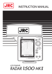
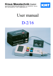
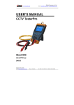
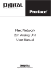
SMS RTU
User Manual
SMS RTU User Manual
Page 2
Manual Revision No. 1.00
Dated October 2004
Copyright 2004 to QTech Data Systems
Christchurch, NEW ZEALAND
Limited
All rights reserved
DISCLAIMER
The information in this document is subject to change without notice
and does not represent a commitment on any part of QTech Data
Systems Limited. While the information contained herein is
assumed to be accurate, QTech Data Systems Limited assumes
no responsibility for any errors or omissions.
QTech Data Systems Limited
Amuri Park, 404 Barbadoes Street
Christchurch, NEW ZEALAND
Ph +64-3-366-3713
Fax +64-3-365-2815
SMS RTU User Manual
Page 3
SMS RTU User Manual
Page 4
TABLE OF CONTENTS
TABLE OF CONTENTS ................................................................................5
INTRODUCTION...........................................................................................7
THE PRODUCT ............................................................................................7
W HAT’S IN THIS MANUAL..............................................................................7
REVISION NOTES ........................................................................................7
Version 1.00 .........................................................................................7
FEATURES ..................................................................................................8
Digital Input Alarms ..............................................................................8
Analog Input Alarms .............................................................................8
Digital Output Controls .........................................................................8
Analog Output Controls ........................................................................9
Remote Diagnostics .............................................................................9
GETTING STARTED ..................................................................................10
SMS STATUS DISPLAY ..............................................................................11
Menu...................................................................................................11
Status Bar ...........................................................................................12
Buttons ...............................................................................................12
Tab Control.........................................................................................13
OPERATOR CONFIGURATION......................................................................14
ID ........................................................................................................15
Name ..................................................................................................15
Number...............................................................................................15
MESSAGE CONFIGURATION........................................................................15
ID ........................................................................................................16
Message .............................................................................................16
DIGITAL ALARM CONFIGURATION ...............................................................16
Alarm ..................................................................................................17
Return to Normal Message ................................................................17
Acknowledge ......................................................................................17
DIGITAL CONTROL CONFIGURATION ...........................................................18
Enable Control....................................................................................19
Authenticate Operator ........................................................................19
ANALOG ALARM CONFIGURATION...............................................................20
Input....................................................................................................20
Alarm1 and Alarm 2............................................................................21
SMS RTU User Manual
Page 5
TABLE OF CONTENTS
Escalations .........................................................................................21
Return to Normal Message ................................................................22
Acknowledge ......................................................................................22
Periodic...............................................................................................22
ANALOG CONTROL CONFIGURATION ..........................................................23
Output Scale.......................................................................................24
Control ................................................................................................24
Authenticate Operator ........................................................................24
REMOTE DIAGNOSTICS ..............................................................................25
SMS MESSAGE FORMAT ...........................................................................26
RTU Originated Messages (Sent by the RTU to the Operator) .........26
<Message Identifier> ..........................................................................27
[<Label>].............................................................................................27
[= <Value> [<Units>]]..........................................................................27
[( <User Message>)]...........................................................................27
Operator Originated Messages (Sent by the Operator to the RTU)...28
<Label>...............................................................................................28
<Command> [(<Value>)] ....................................................................29
INTRODUCTION
The Product
What’s in this Manual
This manual contains the following sections:
Throughout the manual NOTE’s and TIP’s (shown in green italic letters) are
included to give related suggestions, explanations and additional
information, etc.
QTech Data Systems Limited is referred to as QTech throughout this
manual.
Revision Notes
Version 1.00
SMS RTU User Manual
Page 7
FEATURES
The new SMS RTU has the following features implemented
Digital Input Alarms
•
•
•
•
•
•
•
•
1 alarm for each input (max 255)
Real-time input state and alarm status display
Up to 3 escalations for alarm
Separate recipient, message and delays for alarm and escalations
Return to normal messages for each alarm
Acknowledge for individual alarms
Configurable output change on acknowledge
Current input state available by SMS query
Analog Input Alarms
•
•
•
•
•
•
•
•
•
•
•
•
•
2 alarm for each input (max 128)
Real-time input level display either raw or scaled
Real time alarm status display
Scaling of alarm triggering values
Current input level available in alarm SMS either raw or scaled
4 Triggering conditions for each alarm
Up to 3 escalations for each alarm
Separate recipient, message and delays for alarm and escalations
Return to normal messages for alarms
Acknowledge for individual alarms
Configurable output change on alarm acknowledge
Current input level available by SMS query either raw or scaled
Periodic SMS of input value either raw or scaled
Digital Output Controls
•
•
1 Control for each output (max 255)
Real-time output state display
SMS RTU User Manual
Page 8
FEATURES
•
•
•
•
Current output state available by SMS query
Set output state by SMS
Authentication of set commands with caller ID
Confirmation of set commands
Analog Output Controls
•
•
•
•
•
•
1 Control for each output (max 128)
Real-time output level display either raw or scaled
Current output level available by SMS query either raw or scaled
Set output level by SMS either raw or scaled
Authentication of set commands with caller ID
Confirmation of set commands
Remote Diagnostics
•
RTU calls Q90 for diagnostics on SMS command
SMS RTU User Manual
Page 9
GETTING STARTED
To configure the SMS RTU some settings have to be enabled with-in Q90.
Please follow these simple steps:
1. Startup Q90 with the RTU connected
2. After loading the settings from the RTU select the Communications
tab
3. Within the RS232 section set the RS232 Device Type to Telephone
Modem
4. Click the Configure button below this option
5. Select your modem type*
6. Check the Messaging box in the Function section
7. Click close
NOTE – Only Wavecom and iPort modems are currently supported for
SMS
The SMS RTU now has its messaging services enabled. To enter the SMS
display mode select SMS from the view menu.
SMS RTU User Manual
Page 10
GETTING STARTED
SMS Status Display
This screen allows you to configure all SMS settings within the unit. If this
is the first time that the display has been shown and an RTU is connected
all the SMS settings will be loaded from the unit. It should look similar to
that shown below. Each of the areas is discussed separately.
Menu
The Menu bar allows different options to those shown in the diagnostics
view. Each option is described below.
•
File
•
o
o
o
View
Open Configuration – Loads an SMS settings file
Save Configuration – Saves an SMS settings file
Exit – Exit Q90
SMS RTU User Manual
Page 11
GETTING STARTED
•
•
o SMS – View SMS display
o Diagnostics – View diagnostics display
Configuration
o Operators – Open operator setup dialog
o Messages – Open message setup dialog
o Modem – Open modem configuration dialog
Help
o Help – Launch help file
o System Info – Launch system info application
o
About – Display QTech contact details
Status Bar
The status bar operates in the same fashion as on the diagnostics display
th
other than the 6 panel shows the status of the modem. The following
status maybe shown:
•
•
•
•
•
SMS Reset – SMS messaging is not configured
SMS Idle – SMS operation normal
SMS Send – Sending SMS message
SMS Receive – Receiving SMS message
SMS Disabled – Modem in use for call
Buttons
There are a number of buttons shown across the bottom of the SMS
display. Not all of these maybe visible or enabled at any one time. Each is
described below.
•
•
•
•
•
•
Edit Operators - Open operator setup dialog
Edit Messages - Open message setup dialog
Load from RTU – Load settings from RTU (Overwrite local settings)
Upload to RTU - Load settings to RTU (Overwrite RTU settings)
Load Status – Load current tab status (Only for use with remote
connection)
Exit – Exit Q90
SMS RTU User Manual
Page 12
GETTING STARTED
Tab Control
The tab control consists of 4 tabs:
•
•
•
•
Digital Alarms
Digital Controls
Analog Alarms
Analog Controls
Each tab displays up to 8 input or outputs at any one time and may have a
scroll bar if needed. Each input / output point will have a subset of the
controls described below.
•
•
•
•
•
•
•
ID – This is the ID of the input or output
Enable – This shows if the alarm or control is enabled
Name – This displays the name or label attached to the alarm or
control
Value – Displays digital state (Open/Closed) or analog value
(Raw/Scaled)
Units – Display analog units if scale being used
Status – Displays alarm status
Config – Opens control or alarm configuration panel
The status shown in each tab does not reflect the local settings but rather
the state of the RTU. Settings must be uploaded before they will be
reflected in the status. Each tab has a separate configuration panel where
settings for each alarm or control can be modified.
SMS RTU User Manual
Page 13
CONFIGURATION
Operator Configuration
Operator names and numbers should be set up first as invalid operator
numbers will prevent settings being saved to the RTU. The operator setup
screen is similar to this.
It is possible to setup 16 different operators within the system, each with a
name and phone number. When the operators are set up they can be used
within the other configuration screens without re-entering. When setup of
operators is finished, OK should be pressed to save the data. Pressing
cancel will cause data to be lost.
SMS RTU User Manual
Page 14
CONFIGURATION
ID
This number is not configurable and shows the index number of the
operator
Name
The name is used to identify each operator within the other configuration
screens and therefore should be easy recognizable. Up to 20 characters
are allowed.
Number
The phone number for the operator should be able to receive and send
SMS messages. It can be entered using a number of formats, ‘+’ signs are
allowed or may be omitted. Country codes are also optional.
Message Configuration
Messages can be set up using this dialog.
SMS RTU User Manual
Page 15
CONFIGURATION
Up to 48 messages can be set up in the system. These messages can
then be configured to alarms and controls to be sent to operators under
certain conditions. When setup of messages is finished, OK should be
pressed to save the data. Pressing cancel will cause data to be lost.
ID
This number is not configurable and shows the index number of the
operator
Message
The message can be up to 20 characters long
Digital Alarm Configuration
Configuration
This panel is reach by selecting the config button beside one of the digital
alarms. It should appear similar to that shown below.
SMS RTU User Manual
Page 16
CONFIGURATION
All the settings for the digital alarm are shown and can be modified. The
digital input the alarm refers to is shown in the top left corner and the name
given to it shown in the top right corner. Once a name is setup the state of
the alarm can be queried. Each setting is described below.
Alarm
The alarm can be enabled by checking the box at the corner of the alarm
section. This section presents a number of options.
•
•
•
•
Condition – Sets the alarm trigger (Open or Closed)
Message – Message to be contained in alarm SMS
Delay – Trigger must be active for this period before alarm
activates
Operator – Recipient of alarm SMS
Return to Normal Message
This feature is enabled by checking the box at the corner of this section.
There is only one setting here which is the message to be contained in the
return to normal SMS. A return to normal message will be sent to all
operators who received an alarm or escalation SMS about this input once
the state returns to normal. (i.e. not trigger state)
Acknowledge
The acknowledge feature allows an operator to stop an alarm escalating.
Once an acknowledgement is received the alarm stays at its current state.
It is also possible to set a digital output when an acknowledgement is
received using the settings in this section. Again this feature can be
activated by selecting the box in the top left corner of this section.
•
•
Change – Select digital output to set on acknowledgement
To – Select new value of output
SMS RTU User Manual
Page 17
CONFIGURATION
When setting up of a digital alarm is finished OK should be pressed to save
the data. Pressing cancel will cause data to be lost.
Digital Control Configuration
This panel is reach by selecting the config button beside one of the controls
on the Digital Controls tab. It should appear similar to that shown below.
All the settings for the digital controls are shown and can be modified. The
digital output the control refers to is shown in the top left corner and the
name given to it shown in the top right corner. Once a name is setup the
state of the control can be queried. Each setting is described below.
SMS RTU User Manual
Page 18
CONFIGURATION
Enable Control
The control can be enabled by selecting the box in the top left corner of this
section. This means that the unit will now accept SMS messages referring
to this control. The format of these messages is shown later. The send
confirmation setting within this section will force the unit to send a SMS
back to the operator when a control is set showing the control state after
processing of the message. This is on the proviso that the caller ID is
presented to the unit.
Authenticate Operator
When this option is selected only certain users will be allowed access to
controls. If an SMS is received from an operator not on the list it will not be
processed.
When set-up of a digital control is finished OK should be pressed to save
the data. Pressing cancel will cause data to be lost.
SMS RTU User Manual
Page 19
CONFIGURATION
Analog Alarm
Alarm Configuration
This panel is reach by selecting the config button beside one of the controls
on the Analog Alarms tab. It should appear similar to that shown below.
All the settings for the analog alarm are shown and can be modified. The
anaolg input the alarm refers to is shown in the top left corner and the
name given to it shown in the top right corner. Once a name is setup the
level of the alarm can be queried. Each setting is described below.
Input
This section controls the scaling of analog levels.
SMS RTU User Manual
Page 20
CONFIGURATION
•
•
•
•
Append Value - Sets whether the analog level should be contained
in alarm and return to normal SMS messages sent to the operator.
Scale Value – This box shows whether analog levels from this
input should be scaled.*
Min / Max - Scale minimum and maximum values must be integers
although scaled values are represented to 2 decimal places.
Units – When a scaled value is displayed, either in the SMS status
display or in a message, the units will also be shown.
NOTE: Raw values are in the range 0-65535; scaled values have a
range of -32768 to 32767
Alarm1 and Alarm 2
Each alarm operates independently on the same input. They can be
enabled by selecting the box in the top right corner of the appropriate
section. The following settings are valid for each alarm.
•
•
•
•
•
Condition – This sets the trigger value(s). Triggering can occur
when the input falls below a certain level, above a certain level,
inside a range or outside a range.
Message – Message to be contained in the alarm SMS
Delay – Trigger must be active for this period before alarm
activates
Operator – Recipient of alarm SMS
Escalations – This button shows the escalation settings
Escalations
There can be up to 3 escalations for each alarm. However they run in
st
nd
rd
order so 1 and 2 escalations must be set up before the 3 . Alarm will not
be escalated past the first un-enabled escalation. Each escalation has the
following settings.
•
•
•
Message – Message to be contained in escalation SMS
Delay – Length of time since last SMS
Operator – Recipient of escalation SMS
SMS RTU User Manual
Page 21
CONFIGURATION
Return to Normal Message
This feature is enabled by checking the box at the corner of this section.
There is only one setting here which is the message to be contained in the
return to normal SMS. A return to normal message will be sent to all
operators who received an alarm or escalation SMS concerning the current
alarm once the level returns to normal. (i.e. not trigger state)
Acknowledge
The acknowledge feature allows an operator to stop an alarm escalating.
Once an acknowledgement is received the alarm stays at its current state.
It is also possible to set a digital output when an acknowledgement is
received using the settings in this section. Again this feature can be
activated by selecting the box in the top left corner of this section.
•
•
Change – Select digital output to set on acknowledgement
To – Select new value of output
Periodic
This section can be enabled in the usual manner, selecting the box at the
top left of the section. It allows a SMS containing the input level to be sent
periodically to a specified operator. There are a number of settings which
may be viewed here depending on the length of period selected.
•
•
Period – Select from one of the following and the options available
o Hourly – Set the minutes past the hour these should be
sent
o Daily – Set the hour (0000-2300) at which the message
should be sent
o Weekly – Set the day (Sun - Sat) and hour (0000-2300) the
message should be sent.
o Monthly* – Set the date (1-31) and hour (0000-2300) the
message should be sent.
Operator – Recipient of periodic SMS
NOTE: If a month does not contain the day number selected then the
SMS will be sent at 0000hours on the first day of the next month. E.g. A
st
message to be sent on the 31 of each month will be sent at 0000 on
st
1 March as there are not 31 days in February
When setting up of an analog alarm is finished OK should be pressed to
save the data. Pressing cancel will cause data to be lost.
SMS RTU User Manual
Page 22
CONFIGURATION
Analog Control Configuration
This panel is reach by selecting the config button beside one of the analog
controls. It should appear similar to that shown below.
All the settings for the analog controls are shown and can be modified. The
analog output the control refers to is shown in the top left corner and the
name given to it shown in the top right corner. Once a name is setup the
level of the control can be queried. Each setting is described below.
SMS RTU User Manual
Page 23
CONFIGURATION
Output Scale
This section refers to the scaling of the output level. Raw values are in the
range 0-65535, scaled values have a range of -32768 to 32767. Scale
minimum and maximum values must be integers although scaled values
are represented to 2 decimal places. Units will also be added to messages
containing scaled values.
Control
The control can be enabled by selecting the box in the top left corner of this
section. When this is done the unit will accept SMS messages referring to
this control. The format of these messages is shown later.
The send confirmation setting within this section will force the unit to send a
SMS back to the operator when a control is set showing the control state
after processing of the message. This is on the proviso that the caller ID is
presented to the unit.
Authenticate Operator
When this option is selected only certain users will be allowed access to
controls. If an SMS is received from an operator not on the list or the caller
ID is not provided it will not be processed.
When set-up of an analog control is finished, OK should be pressed to save
the data. Pressing cancel will cause data to be lost.
SMS RTU User Manual
Page 24
CONFIGURATION
Remote Diagnostics
Remote diagnostics can be connected using the following steps.
1.
2.
3.
4.
5.
Select Diagnostics from View menu
Select Environment Options from Configuration menu
Set remote coms to modem com port
Click OK
Select Remote Configuration from Configuration menu
At this point you have 2 options
o
o
Send SMS to RTU to initiate connection
Enter RTU phone number and click connect
A remote connection is now established between the RTU and Q90. Q90
operates as normal with the exception that SMS settings and status have to
be explicitly requested from the SMS display panel.
If the connection was initiated at the RTU end then a SMS will be sent to
the operator who initiated the session when the session is over, provided
that the caller ID was presented to the RTU.
SMS RTU User Manual
Page 25
CONFIGURATION
SMS Message Format
This section outlines the format of the SMS messages sent to and by the
operator. It should be noted that messages are not case sensitive but no
wildcards are permitted. An invalid message sent to the RTU will result in a
error response SMS from the unit providing that the caller ID was
presented to the unit. The following syntax is used for showing message
structure:
•
•
<> Parameter
[] Optional
RTU Originated Messages (Sent by the RTU to the
Operator)
There are a number of messages which may be sent by the unit. These
are listed below with an example for each type.
•
•
•
•
•
•
Digital alarm (Sent when digital alarm triggered or escalated)
o Alarm ID=1 – Pump Alarm #1 (Pump Malfunction)
Analog alarm (Sent when analog alarm triggered or escalated)
o Alarm ID=2 – Water Level =4.5 m (High water level)
Return to normal (Sent when alarm trigger returns to normal)
o RTN ID=1 – Pump Alarm #1 (Pump OK)
Confirmation (Response to a set message)
o Confirm – Pump Power=OPEN
Query response (Response to a set message)
o Query - Water Level =3.5 m
Invalid Command
o Invalid Command – (Pump Power =querty)
The general message structure is shown here.
<Message Identifier> -
[<Label>]
[= <Value> [<Units>]] [( <User Message>)]
e.g.
Alarm ID=2
–
SMS RTU User Manual
Water Level
= 4.5
m
(High water level)
Page 26
CONFIGURATION
<Message Identifier>
The message identifier can be one of the following, one for each of the
message types shown above. This is will always be present in the
message.
•
•
•
•
•
Alarm ID = <ID> - Alarm message with alarm ID
RTN – Return to normal message
Confirm – Set control confirmation message
Query – Query response
Invalid Command – Error response
[<Label>]
Generally this will show the name given the input / output, however there
are some special cases as shown below.
•
Diag – Remote diagnostics message
[= <Value> [<Units>]]
The value parameter shows the state or level of the input or output. It will
be one of the following. Units will also be included if it is an analog value
and scaled.
•
•
Digital
o
o
Analog
o
o
Open
Closed
0-65535 – Un-scaled value
-32768-32767 – Scaled value to 2 decimal places
[( <User Message>)]
Any user message to be included in the SMS will be contained in brackets
at this point.
SMS RTU User Manual
Page 27
CONFIGURATION
Operator Originated Messages (Sent by the Operator to
the RTU)
There are a number of messages that can be sent by the operator to the
RTU. Each type is listed below with an example.
•
•
•
•
•
•
•
Acknowledge – Acknowledge alarm
o Pump Alarm #1=ACK(1) – Where the Alarm ID = 1
Query – Query input / output
o Water Level = QUERY
Set Analog
o Req. Water Level = VAL(3.6)
Set Digital
o Aux Pump=ON
Remote Diagnostics
o DIAG=PH(03333333) – Where Q90 phone number =
03333333
Cancel alarms
o ALL=CANCEL(YES) Disable alarms
o DIGITAL=DISABLE
The general message structure is shown here.
<Label>
=
Pump Alarm #1
=
<Command>
[(<Value>)]
e.g.
ACK
(1)
<Label>
The label normally refers to the output / input name but there are other
values.
•
•
•
•
•
<Name> – Input / Output Name
DIAG – Identifier for remoter diagnostics
ANALOG – All analog alarms*
DIGITAL – All digital alarms*
ALL – All alarms*
NOTE: Only valid for CANCEL and DISABLE commands
SMS RTU User Manual
Page 28
CONFIGURATION
<Command> [(<Value>)]
The command and values are related and should be as follows
•
•
•
•
•
•
•
Digital Set Commands
o ON – Set digital output to closed
o OFF – Set digital output to open
o TOG – Toggle digital output
Analog Set Command
o VAL (<Value>) – Set analog value
Value - Un-scaled analog level (0-65535)
Value – Scaled value to 2 decimal places (-3276832767)
Acknowledge Command
o ACK(<Value>) – Acknowledge alarm
Value – Alarm ID (1-255)
Query Command
o QUERY – Query input / output
Remote Diagnostics Command
o PH(<Value>) – Connect remote diagnostics
Value – Q90 phone number
Group Acknowledge
o CANCEL(<Value >) – Acknowledge all alarms
Value - Carry out Acknowledge operators?
(Yes/No)
Turn off all alarms
o DISABLE – Disable all alarms*
NOTE: Disabled alarms can only be re-enabled through Q90
SMS RTU User Manual
Page 29