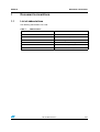
1
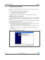
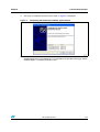
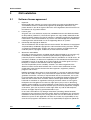
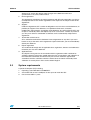
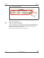
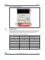
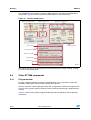
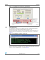
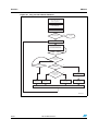
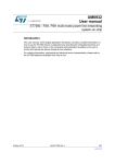
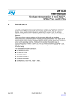
UM1518
User manual
ST7580 power line modem demonstration kit
graphical user interface (GUI)
Introduction
The “ST7580 GUI” is a software tool that allows one or more ST power line modem (PLM)
demonstration boards to be interfaced with a personal computer (PC). Only PLM
demonstration boards equipped with the ST7580 device are supported.
When using the ST7580 GUI the user has complete control of the ST7580 device, having
access to all its registers and functions described in [2].
The typical application environment (shown in Figure 1) consists of an ST7580 GUI running
on a PC and communicating through a USB connection with a PLM demonstration kit
equipped with the ST7580 product, such as the EVALKITST7580-1 (consisting of an
EVALST7580-1 modem board and an EVLALTAIR900-M1 power supply board).
Figure 1.
ST7580 typical application environment
MAINS
Plug
ALTAIR4-900 Power Supply
Evaluation Board
(EVLALTAIR900-M1)
EVALKITST7580-1
ST7580 PLM Evaluation Board
(EVALST7580-1)
USB
Cable
ST7580 GUI
PERSONAL COMPUTER
(PC)
AM16520v1
December 2012
Doc ID 022791 Rev 2
1/37
www.st.com
Contents
UM1518
Contents
1
Document conventions . . . . . . . . . . . . . . . . . . . . . . . . . . . . . . . . . . . . . . . 5
1.1
List of abbreviations . . . . . . . . . . . . . . . . . . . . . . . . . . . . . . . . . . . . . . . . . . 5
2
Connection procedure . . . . . . . . . . . . . . . . . . . . . . . . . . . . . . . . . . . . . . . 6
3
GUI installation . . . . . . . . . . . . . . . . . . . . . . . . . . . . . . . . . . . . . . . . . . . . . 8
4
5
6
2/37
3.1
Software license agreement . . . . . . . . . . . . . . . . . . . . . . . . . . . . . . . . . . . . 8
3.2
System requirements . . . . . . . . . . . . . . . . . . . . . . . . . . . . . . . . . . . . . . . . . 9
3.3
Installing the software . . . . . . . . . . . . . . . . . . . . . . . . . . . . . . . . . . . . . . . . 10
Getting started . . . . . . . . . . . . . . . . . . . . . . . . . . . . . . . . . . . . . . . . . . . . . 12
4.1
Introduction . . . . . . . . . . . . . . . . . . . . . . . . . . . . . . . . . . . . . . . . . . . . . . . 12
4.2
Opening the COM . . . . . . . . . . . . . . . . . . . . . . . . . . . . . . . . . . . . . . . . . . 13
Services . . . . . . . . . . . . . . . . . . . . . . . . . . . . . . . . . . . . . . . . . . . . . . . . . . 15
5.1
Basic modem configuration . . . . . . . . . . . . . . . . . . . . . . . . . . . . . . . . . . . 15
5.2
Power line communication: transmission and reception . . . . . . . . . . . . . . 16
5.2.1
Power line transmission command . . . . . . . . . . . . . . . . . . . . . . . . . . . . 16
5.2.2
Power line confirm command . . . . . . . . . . . . . . . . . . . . . . . . . . . . . . . . . 17
5.2.3
Power line reception command . . . . . . . . . . . . . . . . . . . . . . . . . . . . . . . 18
5.3
MIB operations . . . . . . . . . . . . . . . . . . . . . . . . . . . . . . . . . . . . . . . . . . . . . 19
5.4
Other ST7580 commands . . . . . . . . . . . . . . . . . . . . . . . . . . . . . . . . . . . . 20
5.4.1
Ping commands . . . . . . . . . . . . . . . . . . . . . . . . . . . . . . . . . . . . . . . . . . . 20
5.4.2
Reset commands . . . . . . . . . . . . . . . . . . . . . . . . . . . . . . . . . . . . . . . . . . 21
5.4.3
Status message . . . . . . . . . . . . . . . . . . . . . . . . . . . . . . . . . . . . . . . . . . . 22
5.5
Host interface errors . . . . . . . . . . . . . . . . . . . . . . . . . . . . . . . . . . . . . . . . . 22
5.6
Ping session . . . . . . . . . . . . . . . . . . . . . . . . . . . . . . . . . . . . . . . . . . . . . . . 23
5.6.1
Ping protocol . . . . . . . . . . . . . . . . . . . . . . . . . . . . . . . . . . . . . . . . . . . . . 24
5.6.2
Ping Master session . . . . . . . . . . . . . . . . . . . . . . . . . . . . . . . . . . . . . . . 29
5.6.3
Ping Slave session . . . . . . . . . . . . . . . . . . . . . . . . . . . . . . . . . . . . . . . . . 31
5.6.4
Starting and stopping a Ping session . . . . . . . . . . . . . . . . . . . . . . . . . . 34
References . . . . . . . . . . . . . . . . . . . . . . . . . . . . . . . . . . . . . . . . . . . . . . . . 35
Doc ID 022791 Rev 2
UM1518
7
Contents
Revision history . . . . . . . . . . . . . . . . . . . . . . . . . . . . . . . . . . . . . . . . . . . 36
Doc ID 022791 Rev 2
3/37
List of figures
UM1518
List of figures
Figure 1.
Figure 2.
Figure 3.
Figure 4.
Figure 5.
Figure 6.
Figure 7.
Figure 8.
Figure 9.
Figure 10.
Figure 11.
Figure 12.
Figure 13.
Figure 14.
Figure 15.
Figure 16.
Figure 17.
Figure 18.
Figure 19.
Figure 20.
Figure 21.
Figure 22.
Figure 23.
Figure 24.
Figure 25.
Figure 26.
Figure 27.
4/37
ST7580 typical application environment . . . . . . . . . . . . . . . . . . . . . . . . . . . . . . . . . . . . . . . . 1
Hardware update wizard screen . . . . . . . . . . . . . . . . . . . . . . . . . . . . . . . . . . . . . . . . . . . . . . 6
Completing the found new hardware update wizard. . . . . . . . . . . . . . . . . . . . . . . . . . . . . . . 7
ST7580 GUI installation wizard . . . . . . . . . . . . . . . . . . . . . . . . . . . . . . . . . . . . . . . . . . . . . 10
ST7580 GUI destination folder . . . . . . . . . . . . . . . . . . . . . . . . . . . . . . . . . . . . . . . . . . . . . . 10
GUI setup start . . . . . . . . . . . . . . . . . . . . . . . . . . . . . . . . . . . . . . . . . . . . . . . . . . . . . . . . . . 11
GUI setup finish . . . . . . . . . . . . . . . . . . . . . . . . . . . . . . . . . . . . . . . . . . . . . . . . . . . . . . . . . 11
ST7580 GUI . . . . . . . . . . . . . . . . . . . . . . . . . . . . . . . . . . . . . . . . . . . . . . . . . . . . . . . . . . . . 13
Modem connection procedure . . . . . . . . . . . . . . . . . . . . . . . . . . . . . . . . . . . . . . . . . . . . . . 14
Modem connection success . . . . . . . . . . . . . . . . . . . . . . . . . . . . . . . . . . . . . . . . . . . . . . . . 14
Modem configuration . . . . . . . . . . . . . . . . . . . . . . . . . . . . . . . . . . . . . . . . . . . . . . . . . . . . . 15
Power line transmission box . . . . . . . . . . . . . . . . . . . . . . . . . . . . . . . . . . . . . . . . . . . . . . . . 17
Transmission notifications . . . . . . . . . . . . . . . . . . . . . . . . . . . . . . . . . . . . . . . . . . . . . . . . . 17
Power line confirm box . . . . . . . . . . . . . . . . . . . . . . . . . . . . . . . . . . . . . . . . . . . . . . . . . . . . 18
Reception notification . . . . . . . . . . . . . . . . . . . . . . . . . . . . . . . . . . . . . . . . . . . . . . . . . . . . . 19
Position of MIB objects . . . . . . . . . . . . . . . . . . . . . . . . . . . . . . . . . . . . . . . . . . . . . . . . . . . . 20
PingRequest and PingConfirm graphical tools . . . . . . . . . . . . . . . . . . . . . . . . . . . . . . . . . . 21
ResetRequest command: console view . . . . . . . . . . . . . . . . . . . . . . . . . . . . . . . . . . . . . . . 21
ResetIndication command: console view . . . . . . . . . . . . . . . . . . . . . . . . . . . . . . . . . . . . . . 22
Status message fields. . . . . . . . . . . . . . . . . . . . . . . . . . . . . . . . . . . . . . . . . . . . . . . . . . . . . 22
Host interface error occurrence . . . . . . . . . . . . . . . . . . . . . . . . . . . . . . . . . . . . . . . . . . . . . 23
Ping session: Master and Slave tabs . . . . . . . . . . . . . . . . . . . . . . . . . . . . . . . . . . . . . . . . . 24
Payload subfields on DL frames of Ping session . . . . . . . . . . . . . . . . . . . . . . . . . . . . . . . . 25
Ping session: Master flowchart . . . . . . . . . . . . . . . . . . . . . . . . . . . . . . . . . . . . . . . . . . . . . . 26
Ping session: slave flowchart . . . . . . . . . . . . . . . . . . . . . . . . . . . . . . . . . . . . . . . . . . . . . . . 28
Ping Master tab. . . . . . . . . . . . . . . . . . . . . . . . . . . . . . . . . . . . . . . . . . . . . . . . . . . . . . . . . . 29
Ping Slave tab . . . . . . . . . . . . . . . . . . . . . . . . . . . . . . . . . . . . . . . . . . . . . . . . . . . . . . . . . . 32
Doc ID 022791 Rev 2
UM1518
Document conventions
1
Document conventions
1.1
List of abbreviations
The following abbreviations are used:
Table 1.
Abbreviations
Abbreviation
Description
PRE
Preamble
UW
Unique word
MIB
Management information base
ZC
Zero-crossing
PHY
Physical layer
DL
Data link layer
Doc ID 022791 Rev 2
5/37
Connection procedure
2
UM1518
Connection procedure
In order to connect the EVALKITST7580-1 to the PC, the user must follow the instructions
below:
1.
Connect the board to the PC using a mini-USB cable.
2.
Plug a power cable into the board AC power plug.
3.
Plug the power cable into the power socket.
As soon as the board is powered, the LEDs DL1, DL2 on EVALST7580-1 switch on.
USB/UART adapter driver installation
The USB communication between the EVALKITST7580-1 and the PC is managed through
the onboard STM32 microcontroller, whose embedded default code acts as a USB to UART
bridge.
In order to allow the PC to properly recognize this microcontroller application, the installation
of a proper software driver is necessary.
Assuming that the device drivers are not yet installed, the user must:
1.
Download the latest available virtual COM port (VCP) drivers from the ST website (at
www.st.com) and unzip them to a location on the host PC.
2.
Launch the setup file “VCP_V1.3.1_Setup.exe” to install the virtual COM port driver on
the PC.
3.
When the screen shown in Figure 2 is displayed, click “Next” to proceed with the
installation.
Figure 2.
6/37
Hardware update wizard screen
Doc ID 022791 Rev 2
UM1518
Connection procedure
4.
The setup is completed and the screen shown in Figure 3 is displayed.
Figure 3.
5.
Completing the found new hardware update wizard
Connect the EVALKITST7580-1 to a spare USB port on the host PC: an
“STMicroelectronics virtual COM port” is recognized by the PC device manager and the
EVALST7580-1 is installed and ready to use.
Doc ID 022791 Rev 2
7/37
GUI installation
UM1518
3
GUI installation
3.1
Software license agreement
1.
Important
Before loading this software you must read carefully and agree to the following terms
and conditions which are automatically agreed to by loading this Software or any
portion thereof. If you do not agree to the terms of this Agreement, do not install or use
this Software or any portion thereof.
2.
License grant
ST grants you a non-exclusive, royalty-free, worldwide license to this Software written
for ST products (“Software”). You have the right to use, copy, modify and distribute the
Software with ST products only. All ST software is required to contain the ST copyright
notice which is not to be removed for any reason. You acknowledge that the Software is
not designed nor authorized for use in life supporting devices or systems.
3.
Ownership and copyright of Software
Title to the Software and all copies thereof remain with ST. The Software is copyrighted
and protected by worldwide copyright laws and international treaty provisions. Except
as expressly provided herein, ST does not grant any express or implied right to you
under ST patents, copyrights, trademarks, or trade secret information.
4.
Warranties and liabilities
ST makes no warranty express or implied including but not limited to, any warranty of (i)
marketability or suitability for a particular purpose and/or (ii) requirements, for a
particular purpose in relation to the Software which is provided on an “AS IS” basis. All
warranties, conditions, or other terms implied by law are excluded to the fullest extent
permitted by law. ST is not liable for any claim made by you and/or against you by a
third party, in relation to the Software under this Agreement.
You take responsibility for the suitability, selection, use and management of the
Software and the results obtained there from as well as their combination and the
combination of the elements thereof with other apparatus, equipment, products,
programs and services.
Nothing contained in these terms is to be construed as a warranty or representation by
ST as to the validity or scope of any and all IPR in respect of which a license is herein
granted or constitutes a warranty or representation that any manufacture, use or sale
by you hereunder are free from infringement of any Intellectual Property Rights (IPR)
other than those under which and to the extent to which rights thereto are granted
hereunder or constitute an agreement to bring or prosecute actions or suits against
third parties for infringements or confer any right upon a party to use in advertising,
publicity or other medium, any name trademark or trade name or any other contraction,
abbreviation, or simulation thereto of the other party or confer by implication, estoppel
or otherwise, upon you any license or other right under any and all IPR except the
licenses and rights expressly granted hereunder to you.
In no event is ST liable for any damages whatsoever (including, without limitation,
damages for loss of business revenue or profits, business interruption, loss of business
information or other pecuniary loss) arising out of the use of or the inability to use the
Software as part of an ST application. ST does not assume any responsibility for any
errors that may appear in the Software nor any responsibility to support or update the
8/37
Doc ID 022791 Rev 2
UM1518
GUI installation
Software. ST retains the right to make changes to the Software and its test
specifications at any time, without notice.
5.
Entire agreement
This Agreement constitutes the entire agreement with ST and supersedes any prior or
contemporaneous oral or written agreements with respect to the subject matter of this
Agreement.
6.
Support
Under this Agreement, ST is under no obligation to assist in the use of the Software, to
provide you support of the Software, or to provide maintenance, correction,
modification, enhancement, or upgrades to the Software. Any action taken by ST in this
respect is unilaterally taken and subject only to ST assessment - without any notice to
you. Any such action is considered as Software and is automatically subject to this
Agreement.
7.
Termination of this license
ST is entitled to terminate this Software License Agreement at any time if you are in
breach of any of the terms of this Agreement. Upon termination, you must immediately
destroy the Software.
8.
Export regulations
You undertake to comply with all applicable laws, regulations, decrees and ordinances
related to your use of the Software.
9.
Applicable laws
Any dispute arising out of or in connection with this agreement which could not be
amicably settled is to be finally settled under the rules of conciliation and arbitration of
the international Chamber of Commerce by one or more arbitrators appointed in
accordance with the said Rules which the Parties know and elect irrevocably. Such
arbitration is to take place in Paris and be held in English.
3.2
System requirements
A personal computer (PC) including:
1.
Operating system Windows NT/2000/XP/7.
2.
A hard disk with at least 15 MBytes of free space to install the GUI.
3.
One or more USB 1.1 ports.
Doc ID 022791 Rev 2
9/37
GUI installation
3.3
UM1518
Installing the software
Follow the instructions below to install the ST7580 GUI software.
1.
Extract the contents of the archive in a new directory.
2.
Launch “setup.exe” to start the install procedure.
3.
Press “Next” button (Figure 4):
Figure 4.
4.
Choose an installation path (the default path is suggested) and press the “Next” button,
(Figure 5).
Figure 5.
10/37
ST7580 GUI installation wizard
ST7580 GUI destination folder
Doc ID 022791 Rev 2
UM1518
GUI installation
5.
Press the “Next” button to start the installation (Figure 6).
Figure 6.
6.
GUI setup start
Once the installation has completed, press the “Finish” button to conclude the process,
(Figure 7).
Figure 7.
GUI setup finish
Doc ID 022791 Rev 2
11/37
Getting started
UM1518
4
Getting started
4.1
Introduction
The ST7580 GUI gives the user complete control of the ST7580 device, with full access to
all the settings and functions described in [2]. The GUI can be used to:
●
Establish a connection to the ST7580 modem
●
Configure the ST7580 and manage all its settings
●
Perform any transmission and reception of data over the power line
●
Open a Ping session, where at least two modems (a Master device and one or more
Slave devices) can communicate exchanging data.
A single instance of the ST7580 GUI can handle only one EVALST7580-1 board at a time.
Figure 8 shows the main window of the ST7580 GUI. The panel is divided into two sections:
1.
Console: box displaying all the messages exchanged with the node. The messages
can be cleared or saved in a .txt file through options on the “Tools” menu bar;
2.
Node panel: used to control an ST7580 node; it is divided into five tabs to easily
change between the main service blocks of the node:
–
The properties and services of the connection to the PC;
–
The device's basic configuration, related to MIB objects 00h (modem
configuration) and 01h (PHY configuration);
–
The characteristics of the exchanged power line frames (for both transmitted and
received frames);
–
The access (writing, reading, erasing) to the MIB objects.
–
The settings to open a Ping session (selecting Master or Slave role) and display
the communication results.
A point in the top part of this window always displays the composition of the status message
returned by the modem and the occurrence of error during the last requested command:
12/37
Doc ID 022791 Rev 2
UM1518
Getting started
Figure 8.
ST7580 GUI
Console
1
Node
Panel
2
AM16527v1
4.2
Opening the COM
To establish communication with the EVALST7580-1 demonstration board:
1.
Manually select the COM port number associated to the board.
2.
Select the desired baud rate. Note that the EVALST7580-1 board has a factory default
baud rate equal to 57600 bps.
Doc ID 022791 Rev 2
13/37
Getting started
Figure 9.
UM1518
Modem connection procedure
AM11954v1
If the connection is properly established, the light switches to green, and the console
displays a positive notification and the status message returned by the modem:
Figure 10. Modem connection success
AM11955v1
14/37
Doc ID 022791 Rev 2
UM1518
Services
5
Services
5.1
Basic modem configuration
At power-on, the default values stored in the MIB objects are reported in [2]. From a power
line communication point of view, it is already set to properly received frames (in compliance
with values stored in MIB objects Modem configuration 00h and PHY layer configuration
01h) and to accept transmission requests.
If the user wants to change, at any moment, the two first MIB values:
1.
Modem configuration 00h;
2.
PHY configuration 01h.
All their parameters are selectable in the Modem configuration tab:
Figure 11. Modem configuration
Modem
Configuraon
(MIB object 00h)
1
PHY Layer
Configuraon
(MIB object 01h)
2
AM11956v1
Doc ID 022791 Rev 2
15/37
Services
UM1518
The four buttons in the Modem configuration tab, highlighted by the red squares, execute
correspondingly:
5.2
●
Modem configuration write: it performs an “MIB Write Request” command automatically
built with MIB index 00h and data as selected in the objects above;
●
Modem configuration read: it performs an “MIB Read Request” command automatically
built with MIB index 00h; if the command is properly executed, the data contained in the
expected “MIB Read Confirm” (sent by the ST7580) is extracted and displayed in the
objects above;
●
PHY configuration write: as the previous “Modem Configuration Write”, it performs an
MIB Write Request on the MIB object 01h (PHY layer configuration);
●
PHY configuration read: as the previous “Modem Configuration Read”, it performs an
MIB Read Request on the MIB object 01h (PHY layer configuration).
Power line communication: transmission and reception
In order to put into place a proper power line communication through the GUI, it is enough to
power on the EVALST7580-1 and to open the USB port as explained in Section 4.2.
The “Communication” tab contains all the parameters for ST7580 commands related to
power line communication:
5.2.1
●
“Transmission” box: refers to three “Data Request” commands and contains all their
parameters and data to allow the user to choose the transmission settings;
●
“Confirm” box: displays the parameters of the last “Data Confirm” received from the
ST7580 device;
●
“Reception” box: shows the parameters and the data of the last “Data Indication”
received.
Power line transmission command
As shown in Figure 12, the transmission box contains:
1.
2.
16/37
The “TX Layer” drop-down menu: through this parameter it is possible to choose which
kind of Data Request command the GUI addresses to the ST7580.
–
The PHY_Data selection determines a “PHY Data Request” command;
–
The DL_Data selection determines a “DL Data Request” command;
–
The SS_Data selection determines a “SS Data Request” command.
All transmission parameters to be filled in a data request command; note that:
–
“TX Gain” value is accessible if “Gain Selector” bit is equal to “Custom” value only;
–
“SS Header Length” value is accessible if selected “TX Layer” value is equal to
“SS_Data” only.
3.
The Payload box where the data to be transmitted must be expressed in hexadecimal
characters;
4.
The length (in bytes) of the inserted Payload data, automatically calculated and
displayed.
5.
The Data Request button that builds a Data Request command and transmits it to the
ST7580 connected device.
Doc ID 022791 Rev 2
UM1518
Services
Figure 12. Power line transmission box
$ATA2EQUEST
&ORMAT
4RANSMISSION
0ARAMETERS
4RANSMISSION$ATA
0AYLOAD
,ENGTH $ATA2EQUEST
"UTTON
!-V
After pressing the Data Request command, the console displays it, followed by the message
returned by the ST7580, i.e. either a corresponding Confirm or Error message, as displayed
in Figure 13.
Figure 13. Transmission notifications
AM11958v1
5.2.2
Power line confirm command
The confirm box, as depicted in Figure 14, shows the parameters of the last Data Confirm
command.
A green/red LED reports the success of the previous Data Request.
Doc ID 022791 Rev 2
17/37
Services
UM1518
Figure 14. Power line confirm box
#ONFIRM
PARAMETERS
#ONFIRM3TATUS
!-V
In the case of a negative result returned by the ST7580 after a previous Data Request, the
confirm status LED only is refreshed to an “off” status, whereas the other parameters in the
“Confirm” box are not updated.
5.2.3
Power line reception command
In the case of reception of a Data Indication (PHY, DL or SS) or a SnifferIndication (DL or
SS) sent by the ST7580 after a data reception over the power line, the command type is
displayed on the console, while with received data, the frame format and electrical
parameters are returned in the reception box.
Figure 15 reports the GUI status after a DL_DataIndication:
18/37
Doc ID 022791 Rev 2
UM1518
Services
Figure 15. Reception notification
Received Command
1
Electrical Parameters
Frame Format
4
2
Received Data
3
AM11960v1
5.3
MIB operations
The MIB objects are all accessible through the ST7580 GUI, in accordance with the possible
operations and the range of values, as presented in [2]. Table 2 lists the correspondence
between MIB objects and the tab where they are accessible in the ST7580 GUI:
Table 2.
MIB objects access through ST7580 GUI
MIB object index
MIB object name
ST7580 GUI tab
00h
Modem configuration
Modem configuration
01h
PHY configuration
Modem configuration
02h
SS key
MIB
04h
Last data indication
MIB
05h
Last TX confirm
MIB
06h
PHY_Data
MIB
07h
DL_Data
MIB
08h
SS_Data
MIB
09h
Host interface timeout
COM settings
0Ah
Firmware version
COM settings
Doc ID 022791 Rev 2
19/37
Services
UM1518
The ST7580 GUI automatically handles the MIB subfields in accordance with MIB object
composition. Figure 16 shows the position of MIB objects inside the GUI tabs:
Figure 16. Position of MIB objects
09h Host Interface Timeout
0Ah Firmware Version
02h SS Key
00h Modem Configuration
01h PHY Configuration
04h Last Data Indication
05h Last TX Confirm
06h PHY Data
07h DL Data
08h SS Data
AM11961v1
The buttons present on the GUI perform the allowed operations (writing, reading, erasing)
on each corresponding object.
5.4
Other ST7580 commands
5.4.1
Ping commands
Through a dedicated button located in the COM Settings tab, it is possible to send to the
ST7580 a PingRequest command with editable data Payload.
After the execution of the PingRequest command, a PingConfirm command is expected: the
success of the previous request and data received are displayed through a dedicated LED
and box.
Figure 17 shows all the graphical objects dedicated to the PingRequest and PingConfirm
commands:
20/37
Doc ID 022791 Rev 2
UM1518
Services
Figure 17. PingRequest and PingConfirm graphical tools
Data to be inserted
within a PingRequest
command
Data returned by
ST7580 within a
PingConfirm command
Button to send a PingRequest
to ST7580
5.4.2
Led displaying the
PingConfirm status
AM11962v1
Reset commands
The ResetRequest command can be properly formed and sent to the modem through a
dedicated button on the bottom part of the Modem Configuration tab.
After pressing the button, the console displays the command sequence, declaring it as a
“Software Reset” and returning the auto-reconfiguration feature status, as displayed in
Figure 18:
Figure 18. ResetRequest command: console view
AM11963v1
In the case of a ResetIndication command (generated for example if the RESETN pin is
driven at a low state), the unsolicited occurrence is directly displayed on the console and is
named as a “Power On Reset” event, as shown in Figure 19:
Doc ID 022791 Rev 2
21/37
Services
UM1518
Figure 19. ResetIndication command: console view
AM11967v1
5.4.3
Status message
The status message is automatically displayed with all its fields in the box below the GUI
console. The meaning of each field is explained in Figure 20:
Figure 20. Status message fields
Estimated
Temperature
Configuration
status
Transmission
Status
Active Layer
Reception
Status
Overcurrent
Flag
AM11964v1
5.5
Host interface errors
The errors on a host interface communication flow (i.e. Timeout elapsed, etc.) are reported
on the “Error” LED below the GUI console. Figure 21 shows an occurrence of a host
interface error, when the TACK timeout has elapsed:
22/37
Doc ID 022791 Rev 2
UM1518
Services
Figure 21. Host interface error occurrence
Error LED
5.6
AM11965v1
Ping session
In order to evaluate the reliability of a communication between two or more devices, a Ping
session can be performed. A ping session consists of a Master sending a sequence of
messages to one or more Slaves. If the messages are correctly received by Slaves, they are
re-sent to the Master with the same electrical parameters and Payload data, enabling the
application to collect statistical data.
When a Ping session is active, the GUI adds some automatic services to the functions and
commands of the ST7580 device.
The Ping tab displays different control and indicator values in accordance with the role that
the EVALKITST7580 board, handled by the GUI, has during the Ping session.
Figure 22 shows both Ping tabs for Master and Slave nodes:
Doc ID 022791 Rev 2
23/37
Services
UM1518
Figure 22. Ping session: Master and Slave tabs
AM16521v1
The Ping session can be logged in a .txt file, selecting the "Save Logs" switch located on the
right-top edge of both Master and Slave tab. The resulting file records the powerline activity
(both transmitted and received frames) of the node over the Ping session.
5.6.1
Ping protocol
The Ping session consists of an exchange of DL frames between the Master node and one
or more Slave nodes.
Master node
The Master node sends a powerline frame sequence with selectable electrical features:
●
Carrier frequency value (it is overwritten in the MIB object 01h - PHY configuration as
RX operating frequency);
●
Modulation type as in ordinary DL_DataRequest command;
●
TX Gain parameter (it is overwritten in the MIB object 01h - PHY configuration).
These electrical characteristics are equal to each transmitted frame in all frames sent by the
Master over Ping session.
The GUI tool adds specific subfields to the Payload field of the exchanged DL frames, as
shown in Figure 23, where the blue parts need to be specified by the user, while the green
one is automatically built by the GUI tool. The red blocks refer to the fields automatically
handled by the ST7580.
The Payload length selected by the user is limited to 244 bytes.
24/37
Doc ID 022791 Rev 2
UM1518
Services
Figure 23. Payload subfields on DL frames of Ping session
Frame
Number
Slave
Address
Length
1 byte 1 byte 1 byte
from 0 up to 246 bytes
from 0 to 244 bytes
Payload
4 byte, LE
CRC
PHY SDU
DL SDU
AM16522v1
The Master sends periodically, with an inter-packet time selected by the user (in seconds), a
burst of DL frames built (see Figure 23) with a fixed value on Slave Address subfields (1
byte) and an increment value on Frame number subfield. The Frame number value is
managed by the GUI and it is equal to 0 on the first DL frame of the Ping session, it
increases on next sent frames up to value 255 hexadecimal FF. The next frame, after that
with a number of frames equal to 255, is built with a subfield equal to 0.
The user chooses the number of frames to be transmitted by the Master during the Ping
session, which ends after sending this number of frames.
After each sent frame, a further frame is expected to be received to successfully accomplish
a single Ping loopback, within an interval with length equal to inter-packet time. In case of a
frame received by the Master node, the GUI compares the electrical parameters and
Payload to those for transmitted frame. Three cases are taken into account by the GUI:
1. A DL_DataIndication has been notified by the modem reporting the same electrical
features (modulation, carrier frequency), the Payload length and data values (over the three
subfields) as the last ones to be transmitted. The single Ping loopback is reported as
successful by increasing a dedicated "Ping OK" counter;
2. A DL_DataIndication has been notified by the modem reporting different electrical
features or Payload data. As DL_DataIndication assumes a correct check on CRC of the
powerline frames, the communication link from Slave to Master is considered as good, while
the difference of frames are supposed to be due to the link from Master to Slave. Hence, the
single Ping loopback is reported as failed, by increasing a dedicated "Ping Wrong Link 1"
counter;
3. A DL_SnifferIndication has been notified by the modem. The communication link from
Slave to Master is judged to be the cause of the wrong single Ping loopback and dedicated
"Ping Wrong Link 2" counter increases.
In case of no Indication message notified by the ST7580 within the inter-packet time interval,
the single Ping loopback is judged as failed, by increasing the corresponding "Ping Not OK"
counter.
Figure 24 reports the flowchart of Master node throughout Ping session:
Doc ID 022791 Rev 2
25/37
Services
UM1518
Figure 24. Ping session: Master flowchart
DL operating layer, Sniffer flag activated
written on MIB object 00h
(Modem configuration)
TX Frequency, TX gain
overwritten on MIB object 01h
(PHY configuration)
Transmitted frames =0
Yes
Transmitted frames =
total frame number?
Ping Stop
No
Start Timeout (Inter-packet time value)
Transmit frame
Fixed modulation, gain,frequency
Selected Slave Number, Data
Frame Number = Transmitted frame
Frame transmitted?
No
Yes
Indication message
received?
No
Yes
No
Timeout elapsed?
DL_DataIndication
received?
Yes
No
Yes
Yes
"Ping Not Ok" counter
Incremented
Electrical features,
Payload data equal
to those sent?
No
"Ping Wrong Link 1" counter
Incremented
"Ping Ok" counter
Incremented
DL_SnifferIndication received
"Ping Wrong Link 2" counter
Incremented
Transmitted frame number has incremented
AM16523v1
26/37
Doc ID 022791 Rev 2
UM1518
Services
Slave node
When a node is set as "Slave" for a Ping session, it automatically answers each received
frame by sending a packet built with identical electrical features and Payload data.
Before starting the Ping session, the node needs to be configured with two frequency values
for reception and the corresponding functional modulations. These values are overwritten to
MIB object 01h (Physical configuration) and the node is set to work on a dual channel
reception.
From a functional point of view, a Slave Address Number is assigned as well, as 1-byte
value. The Slave node re-transmits the frames with Slave Address subfield (Figure 23)
equal to the Slave Address Number assigned to it.
The GUI allows the user to choose between two Stop conditions:
1.Frame number: the GUI stops the Ping session after the node receives a fixed number of
Indication messages (DL_DataIndication and DL_SnifferIndication);
2.Time: the GUI stops the Ping session after a number of seconds selected by the user (if
the number set through the GUI is equal to 0, the Ping session ends when the "Stop Ping"
button is pressed).
After an Indication message, three cases are taken into account and displayed by the GUI:
1. A DL_DataIndication has been notified by the modem and the Frame Address subfield is
equal to the Frame Address parameter set to the node; the Node sends a powerline frame
with same electrical conditions (Frequency carrier, modulation) and data Payload (in
accordance with Figure 23 subfields). The dedicated "Received OK" counter increases.
2. A DL_DataIndication has been notified by the modem and the Frame Address subfield is
not equal to the Frame Address parameter set to the node; the dedicated "RX Wrong
Address" counter increases and any frame is transmitted.
3. A DL_SnifferIndication has been notified by the ST7580: the dedicated "RX Wrong CRC"
counter increases. However, if the Frame Address subfield is equal to the Frame Address
parameter set to the node, a powerline frame is transmitted with same electrical conditions
(Frequency carrier, modulation) and data payload (in accordance with Figure 23 subfields).
Figure 25 reports the flowchart of Master node throughout the Ping session:
Doc ID 022791 Rev 2
27/37
Services
UM1518
Figure 25. Ping session: slave flowchart
DL operating layer, Sniffer flag activated
written on MIB object 00h
(Modem Configuration)
RX Frequencies, RX modulations
overwritten on MIB object 01h
(PHY Configuration)
Get Stop condition
(Frame Number or Time)
Stop condition = 0
Stop Condition
achieved?
Yes
Ping Stop
No
Indication message
received?
No
Yes
No
Slave Address Number
equal to
set one?
Yes
No
Yes
No
Transmit frame
with modulation, frequency
Slave Number, Data fields equal to the
ones of received frame
DL_DataIndication
received?
Yes
"RX Wrong CRC" counter
Incremented
"Ping Wrong Address" counter
Incremented
No
Frame transmitted?
Yes
"Transmitted frames" counter
incremented
DL_DataIndication
received?
No
Yes
"Received Ok" counter
Incremented
"RX Wrong CRC" counter
Incremented
Received frame number incremented
AM16524v1
28/37
Doc ID 022791 Rev 2
UM1518
5.6.2
Services
Ping Master session
As shown in Figure 26, the following parameters listed in Table 3, can be selected for the
Ping session corresponding to Master device. "Control" parameters are the variables that
can be selected by the user, while "indicators" are automatically displayed by the GUI during
the Ping session.
Figure 26. Ping Master tab
Payload data:
Electrical
parameters on
transmitting
frames
Message
settings
Ping Session activity and results
Doc ID 022791 Rev 2
•
Type
•
Data
•
Length
•
Destination
Slave address
•
Frame number
AM16525v1
29/37
Services
UM1518
Table 3.
Ping session: Master tab parameters
Parameter
Type
Description
Electrical parameters of transmitting frames
Frame modulation
Control
Choice of modulation type for frames to be transmitted during Ping
session
TX frequency [Hz]
Control
Frequency value for frames to be transmitted during Ping session.
Control
Frequency value expressed in the box “TX Freq [Hz]” is written as
reception frequency in MIB object 01h (PHY configuration) in
accordance with the value (high or low) chosen by this switch. If a
combination of these two control values is not allowed, an error is
generated and Ping session doesn’t start.
Control
Selection of the TX Gain to be set for transmitting frames: it can be
used either the value stored in the MIB object 01h (“PHY Cfg”
selection for this switch) or a new one (“New” selection for this
switch) to be expressed in the value box which is overwritten in the
same MIB object.
Control
Selection for data composition of outgoing messages:
-”Fixed” is specified by the user in the box below
- “Random” is automatically generated by the GUI
TX frequency set
(PHY configuration)
TX Gain
Payload data
Type
Length value
Random Payload
length
Data
Slave Destination
Address
Number of frames
Length [bytes] for the transmitting Payload
Control or
- automatically calculated by the GUI for Fixed Payload
indicator
- selected by the user for Random Payload
Control
Selection for Random Payload type only.
- “Fixed” sets the parameter “Length value” expressed in the leftside box as fixed length for each transmitting frame;
- “Max” sets as the maximum length of each randomly generated
frame, whose length is not fixed;
Data of Payload of outgoing powerline frame, displayed in
hexadecimal values only.
Control or - filled in by the user in case of “Fixed” frame type selection and it
indicator is a constant value for each transmitted frame;
-automatically displayed for “Random” frame type selection, its
value is different in each transmitting frame
Control
1- byte field (hexadecimal value) referring to the Slave Address
value. It is inserted by the GUI as the first byte of Payload field of
each DL_DataRequest built throughout the Ping session.
Indicator
1- byte field (hexadecimal value) automatically displayed by the
GUI. It displays the ordinal number of transmitted frame and it is
inserted by the GUI as second byte of Payload field of each
DL_DataRequest built throughout the Ping session.
Message settings
Total frames
30/37
Control
Number of powerline frames that the Ping session sends
throughout the Ping session
Doc ID 022791 Rev 2
UM1518
Services
Table 3.
Ping session: Master tab parameters (continued)
Parameter
Type
Description
Inter-packet time [s]
Control
Interval which the GUI sets during two consecutive transmitted
frames within Ping Session. Minimum value is 1 second.
Reset MIB
counters on start
Control
Selection to erase MIB objects 06h (PHY Data) and 07h (DL Data)
before Ping session starts.
Start and Stop buttons
Start Ping
Control
Button to start the Ping session
Stop Ping
Control
Button to force the Ping session when the transmitted frames are
less than the selected total frame number.
Ping session activity and results
5.6.3
Ping OK
Indicator
Number of Ping loop (transmitted and received) performed without
any wrong received bit.
Ping Wrong Link 1
Indicator
Number of Ping loop (transmitted and received) performed with
wrong received bit during the communication from Master to Slave
Ping Wrong Link 2
Indicator
Number of Ping loop (transmitted and received) performed with
wrong received bit during the communication from Slave to Master
Ping Not OK
Indicator
Number of Ping loop (transmitted and received) performed with no
loopback frame reception by the Master
Frame sent
Indicator
Number of frames successfully transmitted by the Master, updated
by the GUI during the Ping session execution.
Ping active
Indicator
LED displaying the Ping session activity:
-Green when Ping session is active;
-Red when Ping session is not active.
Ping Slave session
As shown in Figure 27, the following parameters, listed in Table 4, can be selected for the
Ping session corresponding to Slave device.
Doc ID 022791 Rev 2
31/37
Services
UM1518
Figure 27. Ping Slave tab
Reception
settings
Slave address
setting
Received frame
features:
•
Slave address
•
Data
•
Length
•
Modulation
•
PGA code
•
SNR value
•
Frequency
channel
Ping session
settings
Ping session activity
and results
AM16526v1
Table 4.
Ping session: Slave tab parameters
Parameter
Type
Description
Reception settings
Control
Frequency channel to be set for reception. It is overwritten
before starting Ping session as “High Frequency” value in MIB
object 01h (PHY configuration)
RX high channel mode
Control
Functional modulation (between PSK and FSK families) on high
channel. It is overwritten before starting Ping session as “RX
high channel modulation” value in MIB object 01h (PHY
configuration)
RX low freq [Hz]
Control
Frequency channel to be set for reception. It is overwritten
before starting Ping session as “Low Frequency” value in MIB
object 01h (PHY configuration)
RX low channel mode
Control
Functional modulation (between PSK and FSK families) on high
channel. It is overwritten before starting Ping session as “RX low
channel modulation” in MIB object 01h (PHY configuration)
Control
1-byte value (hexadecimal value) that sets the address value of
the Slave throughout the Ping session. The Slave retransmits
the received frames with the address field equal to this value.
Control
Selection on stop event for Ping session
- Time: the Ping session ends after a selected time interval (in
seconds)
- Frame numbers: the Ping session ends after reception of a
selected frame number (not necessarily re-transmitted)
RX high freq [Hz]
Slave address settings
Slave address
Ping session settings
Stop condition
32/37
Doc ID 022791 Rev 2
UM1518
Services
Table 4.
Ping session: Slave tab parameters (continued)
Parameter
Type
Description
Ping time[s] or Frame
numbers
Control
Occurrence number of Stop condition selection. The variable is
displayed in accordance with “Stop condition” value.
If Ping Time is set to 0, the Ping session continues until “Stop
Ping” button is pressed.
Reset MIB counters on
start
Control
Selection to erase MIB objects 06h (PHY Data) and 07h (DL
Data) before starting the Ping session.
Start Ping
Control
Button to start the Ping session
Stop Ping
Control
Button to force the Ping session before the Stop condition is
achieved.
Start and Stop buttons
Received frame features
Slave address
Data
Length
Slave address field of the last received frame (i.e., first byte of
Indicator the DL_DataIndication or DL_SnifferIndication received by the
ST7580)
Indicator Payload data (without Slave address field) of the received frame
Indicator Length (in bytes) of the Payload data, calculated by the GUI
Modulation
Indicator Signal modulation of the received frame
PGA code
Indicator PGA value on the received frame
SNR value
Indicator SNR estimation (over UW reception) performed by ST7580
Frequency channel
Indicator RX channel (high or low) on the received frame
Ping session activity and results
Number of seconds elapsed during Ping session. Active if “Stop
condition” is equal to time only, hidden otherwise.
Time count [s]
Indicator
Received OK
Number of received frames with correct CRC (i.e.
DL_DataIndication notified by the ST7580) and Slave address
Indicator field equal to the value set in “Slave Address” control.
These frames are re-transmitted, in accordance with Ping
session rules.
RX Wrong Address
Number of received frames with correct CRC (i.e.
Indicator DL_DataIndication notified by the ST7580) and Slave address
field not equal to the value set in “Slave Address” control.
RX Wrong CRC
Indicator
Number of received frames with wrong CRC (i.e.
DL_SnifferIndication notified by the ST7580).
Frames sent
Indicator
Number of frames successfully transmitted by the Slave,
updated by the GUI during Ping session execution
Ping active
LED displaying the Ping session activity:
Indicator -Green when Ping session is active;
-Red when Ping session is not active.
Doc ID 022791 Rev 2
33/37
Services
5.6.4
UM1518
Starting and stopping a Ping session
For both Master and Slave nodes, the Ping session manually starts by pressing "Start Ping"
button, while the session stops either automatically (if Stop condition is achieved) or
manually, pressing "Stop Ping" button.
34/37
Doc ID 022791 Rev 2
UM1518
6
References
References
1.
ST7580 datasheet: FSK, PSK multi-mode power line networking system-on-chip;
www.st.com/powerline
2.
UM0932: ST7580 - FSK, PSK multi-mode power line networking system-on-chip; Rev 2
www.st.com/powerline
Doc ID 022791 Rev 2
35/37
Revision history
7
UM1518
Revision history
Table 5.
Document revision history
Date
Revision
11-Apr-2012
1
Initial release.
2
Changed: Figure 1, Figure 8, Figure 9, Figure 10, Figure 11,
Figure 12, Figure 13, Figure 15, Figure 16, Figure 17, Figure 18,
Figure 19, Figure 20, Figure 21.
Added Section 5.6.
05-Dec-2012
36/37
Changes
Doc ID 022791 Rev 2
UM1518
Please Read Carefully:
Information in this document is provided solely in connection with ST products. STMicroelectronics NV and its subsidiaries (“ST”) reserve the
right to make changes, corrections, modifications or improvements, to this document, and the products and services described herein at any
time, without notice.
All ST products are sold pursuant to ST’s terms and conditions of sale.
Purchasers are solely responsible for the choice, selection and use of the ST products and services described herein, and ST assumes no
liability whatsoever relating to the choice, selection or use of the ST products and services described herein.
No license, express or implied, by estoppel or otherwise, to any intellectual property rights is granted under this document. If any part of this
document refers to any third party products or services it shall not be deemed a license grant by ST for the use of such third party products
or services, or any intellectual property contained therein or considered as a warranty covering the use in any manner whatsoever of such
third party products or services or any intellectual property contained therein.
UNLESS OTHERWISE SET FORTH IN ST’S TERMS AND CONDITIONS OF SALE ST DISCLAIMS ANY EXPRESS OR IMPLIED
WARRANTY WITH RESPECT TO THE USE AND/OR SALE OF ST PRODUCTS INCLUDING WITHOUT LIMITATION IMPLIED
WARRANTIES OF MERCHANTABILITY, FITNESS FOR A PARTICULAR PURPOSE (AND THEIR EQUIVALENTS UNDER THE LAWS
OF ANY JURISDICTION), OR INFRINGEMENT OF ANY PATENT, COPYRIGHT OR OTHER INTELLECTUAL PROPERTY RIGHT.
UNLESS EXPRESSLY APPROVED IN WRITING BY TWO AUTHORIZED ST REPRESENTATIVES, ST PRODUCTS ARE NOT
RECOMMENDED, AUTHORIZED OR WARRANTED FOR USE IN MILITARY, AIR CRAFT, SPACE, LIFE SAVING, OR LIFE SUSTAINING
APPLICATIONS, NOR IN PRODUCTS OR SYSTEMS WHERE FAILURE OR MALFUNCTION MAY RESULT IN PERSONAL INJURY,
DEATH, OR SEVERE PROPERTY OR ENVIRONMENTAL DAMAGE. ST PRODUCTS WHICH ARE NOT SPECIFIED AS "AUTOMOTIVE
GRADE" MAY ONLY BE USED IN AUTOMOTIVE APPLICATIONS AT USER’S OWN RISK.
Resale of ST products with provisions different from the statements and/or technical features set forth in this document shall immediately void
any warranty granted by ST for the ST product or service described herein and shall not create or extend in any manner whatsoever, any
liability of ST.
ST and the ST logo are trademarks or registered trademarks of ST in various countries.
Information in this document supersedes and replaces all information previously supplied.
The ST logo is a registered trademark of STMicroelectronics. All other names are the property of their respective owners.
© 2012 STMicroelectronics - All rights reserved
STMicroelectronics group of companies
Australia - Belgium - Brazil - Canada - China - Czech Republic - Finland - France - Germany - Hong Kong - India - Israel - Italy - Japan Malaysia - Malta - Morocco - Philippines - Singapore - Spain - Sweden - Switzerland - United Kingdom - United States of America
www.st.com
Doc ID 022791 Rev 2
37/37