1
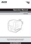
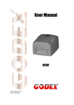
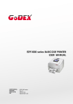
P/N. M4206U-01 Edition 1 December 2002 Century Falcon4 User Manual Table of Contents FCC COMPLIANCE STATEMENT FOR AMERICAN USERS This equipment has been tested and found to comply with the limits for a CLASS A digital device, pursuant to Part 15 of the FCC Rules. These limits are designed to provide reasonable protection against harmful interference when the equipment is operated in a commercial environment. This equipment generates, uses, and can radiate radio frequency energy and, if not installed and used in accordance with the instructions, may cause harmful interference to radio communications. Operation of this equipment in a residential area is likely to cause harmful interference in which case the user will be required to correct the interference at his own expense. EMS AND EMI COMPLIANCE STATEMENT FOR EUROPEAN USERS This equipment has been tested and passed with the requirements relating to electromagnetic compatibility based on the standards EN50081-1 (EN55022 CLASS A) and EN61000-4-2/-3/-4/-5/-6/-8/-11 (IEC Teil 2,3,4). The equipment also tested and passed in accordance with the European Standard EN55022 for the both Radiated and Conducted emissions limits. CAUTION Danger of explosion if battery is incorrectly replaced Replace only with the equivalent type recommended by the manufacture. Dispose of used batteries according to the manufacturer’s instructions. Specifications are subject to change without notice. 1 CHAPTER 1. BARCODE PRINTER ...................................................................................3 1-1. Introduction..................................................................................................................................3 1-2. Printer Options.............................................................................................................................3 1-3. Printer Accessories ......................................................................................................................3 1-4. General Specifications .................................................................................................................4 1-5. Communication Interface ............................................................................................................5 1-6. Printer Parts .................................................................................................................................7 CHAPTER 2. PRINTER INSTALLATION ...........................................................................9 2-1. Ribbon Installation.......................................................................................................................9 2-2. Ribbon Inside/Outside Installation ............................................................................................10 2-3. Label Installation .......................................................................................................................11 2-4. USB Installation.........................................................................................................................13 2-5. USB Uninstallation....................................................................................................................15 2-6. PC Connection ...........................................................................................................................16 CHAPTER 3 .....................................................................................................................17 3-1. Stripper and Internal Rewinder Parts.........................................................................................17 3-2. Stripper and Rewinder Installation ............................................................................................17 3-3. Cutter Parts ................................................................................................................................19 3-4. Cutter Installation ......................................................................................................................19 CHAPTER 4. CONTROL PANEL ....................................................................................21 4-1. LCD/LED Messages ..................................................................................................................21 4-2. General Operation......................................................................................................................21 4-3. Self-Test.....................................................................................................................................22 4-4. Dump Mode ...............................................................................................................................22 4-5. Auto Sensing..............................................................................................................................23 4-6. Setting Mode..............................................................................................................................24 4-7. Error Messages ..........................................................................................................................25 CHAPTER 5. MAINTENANCE AND ADJUSTMENT .........................................................26 5-1. Thermal Print Head Cleaning ....................................................................................................26 5-2. Thermal Print Head Balance Adjustment ..................................................................................26 5-3. Ribbon Tension Adjustment ......................................................................................................27 5-4. Cutter .........................................................................................................................................27 5-5. Troubleshooting .........................................................................................................................28 2 Chapter 1. Barcode Printer 1-1. Introduction The Century Falcon4 is a heavy duty, high performance thermal transfer / direct thermal label printer suitable for large volume printing requirements in industrial applications. With robust metal outer casing and inner mechanism, the Falcon4 is designed to be durable, tough and reliable, even in the harshest environments. Its features are as follows: Print head density of 8 dots or 12dots per mm (203 or 300 dots per inch). Back light LCD display showing graphics and messages in English and simplified Chinese (version dependent). Internal memory card for label, graphics, and fonts download. Real Time Clock for time recording and tracking. Internal 8” label roll capacity and 450M ribbon length (1” core size). Maximum 50” print length. Optional stripper and internal rewinder for efficient operation. Optional cutter for ticketing or receipt printing applications. 1-2. Printer Options Falcon4 (203 DPI) 1-3. Printer Accessories After unpacking, please check the accessories that come with the package, and store appropriately. 1. Barcode printer 4. Empty Ribbon Roll 2. Power cable (110V or 230V) 5. CD (includes Software/Manual/Driver/DLL) 3 3. Quick Start Guide 1-4. General Specifications Model Resolution Print Mode CPU Sensor Location Sensor Type Sensor Detection Print Speed Print Length Print Width Media Ribbon Printer Language Software Resident Fonts Fonts Download Image Handling Barcode Interface Interface Transmission Speed Memory LCD Display Power Real Time Clock Environment Humidity Cert. Approval Printer Dimension Options Falcon4 203 dpi (8 dot/mm) Thermal Transfer / Direct Thermal 16 Bit Moveable, left aligned Reflective, Transmissive Type: Label gap and black mark sensing. Detection: Label length auto sensing and / or program command setting 50.8mm (2”)/sec ~ 152.4mm (6“)/sec 1270mm (50”) 25mm (1”) ~ 104 mm (4.09”) Label Roll: Max. 203mm (8”) Core Diameter: 38.1 mm (1.5”)~ 76.2 mm (3”) Width: 25.0 mm (1“) ~ 118.0 mm (4.65”) Thickness: 0.06~0.25mm (0.002” to 0.009”) Material: Transfer ribbons (wax, hybrid, and resin) Type: Ink inside or ink outside Length: 450M (1471 ft) Width: 30mm ~ 110 mm (1.18” to 4.33”). Inner Core Diameter: 25.4 mm (1”). Ribbon Roll Diameter: 75 mm (2.95“). EZPL (downloadable) Application: QLabel-III DLL & Driver: Microsoft Windows 95, 98, Me, NT 4.0, 2000 and XP 9 resident alphanumeric fonts (included OCR A & B) those are expandable (8 times for EZPL) horizontally and vertically. All fonts in 4 directions rotation (0, 90, 180, 270 degrees), 6,8,10,12,14,18,24,30 points. Windows Bit-map fonts and Asian fonts downloadable. All fonts in 4 directions rotation (0, 90, 180, 270 degrees). Asian fonts in 8 directions rotation. BMP, PCX, Support ICO, WMF, JPG, EMF file through software. Code 39, Code 93, Code 128 (subset A,B,C), UCC 128, UPC A / E (add on 2 & 5), I 2 of 5, EAN 8 / 13 (add on 2 & 5), Codabar, Post NET, EAN 128, DUN 14, MaxiCode, PDF417 & Datamatrix Code Serial, Parallel, USB, PS2 keyboard wedge Baud rate 300 ~ 38400, XON/XOFF, DSR/DTR Standard: 2MB Flash, 2MB DRAM Optional: 2MB Flash Back-light Graphic LCD Display Three bi-color LED lamps: Power, Ready, Error Three Front Panel Keys: Feed, Pause, Cancel 100/110/240VAC, 50/60 Hz – Auto Switching Time and date stamp Operation: 40°F to 104°F (5°C to 40°C) Storage: -40°F to 122°F (-20°C to 50°C) Operation: 30-85%, non-condensing. Free air. Storage: 10-90%, non-condensing. Free air. CE, CUL, FCC Class A Length: 454.58 mm (17.9”) Height: 277.30 mm (10.92”) Width: 275.55 mm (10.85”) Weight: 13 Kg Cutter Stripper with Internal Rewinder 2MB Flash memory module Stand-alone keyboard (KP-180) QR code Specifications are subject to change without notice. 4 1-5. Communication Interface Parallel Interface Handshake Interface cable Pin out : DSTB connects to the printer, BUSY connects to the host : Parallel cable compatible to IBM PC : See below PIN NO. FUNCTION TRANSMITTER 1 2-9 10 11 12 13 14-16 17 18 19-30 31 32 33 34-36 Strobe Data 0-7 Acknowledge Busy Paper empty Select N/C Chassis Ground N/C Signal Ground N/C Fault Signal N/C host host printer printer printer printer host printer ground Serial Interface Serial Default Setting : 9600 baud rate﹑no parity﹑8 data bits﹑1 stop bit﹑XON/XOFF protocol 及RTS/CTS。 Connector Type: DB9 female, pin assignment is as follows: PIN NO. 1 2 3 4 5 6 7 8 9 FUNCTION +5 V TXD RXD N/C GND N/C CTS RTS N/C Serial interface from PC to printer PC(DTE) Falcon4(DCE) --1 1 +5V RXD 2 2 TXD TXD 3 3 RXD DTR 4 4 N/C GND 5 5 GND DSR 6 6 N/C RTS 7 7 CTS CTS 8 8 RTS --9 9 N/C 5 USB Interface Connector Type : Type B PIN NO. 1 2 3 4 FUNCTION USBVCC D- D+ GND PS2 Interface PIN NO. 1 2 3 4 5 6 FUNCTION DATA N/C GND VCC CLOCK N/C PS2 interface from PC to printer Falcon4 PC DATA 1 1 DATA N/C 2 2 N/C GND 3 3 GND VCC 4 4 VCC CLOCK 5 5 CLOCK N/C 6 6 N/C 6 1-6. Printer Parts Please use the following diagrams to identify each printer part. 1 Top Cover 11 Label Width Guide 21 Ribbon Feed Rod 2 Indicator Light 12 Ink Position Lever 22 Label Feed Rods 3 LCD Display 13 Print Head Spring Box 23 Label Feed Guide 4 Control Key 14 Stripper Sensor 24 Fan-Fold Label Insert 5 Ribbon Rod 15 Tear Off Bar 25 Power Socket 6 Bottom Front Cover 16 Printer Mechanism 26 Power Switch 7 Print Head Lever 17 Rewinder Option Cover Plate 27 Parallel Port 8 Ribbon Rewind Shaft 18 Rewinder Connector 28 USB Port 9 Ribbon Supply Shaft 19 Cutter Connector 29 Serial Port 20 Cable Configuration holes 30 PS2 Port 10 Label Roll Bar 7 31 Moveable Sensor Lever 32 Sensor Position Mark 8 33 Moveable Sensor Chapter 2. Printer Installation This printer model has the following print modes: Thermal Transfer (TT) : When printing, ribbon must be installed to transfer the print contents onto the media Direct Thermal (DT) : When printing, no ribbon is necessary; it only requires direct thermal media. Please check the specific print mode, then go into the Setting Mode after power on the printer. 2-1. Ribbon Installation 1. Place the printer onto a smooth surface, and open the top cover. 2. Pull the Print Head Lever out and flip it upward to the right. 3. Take the used ribbon out of the ribbon supply shaft. 4. Place the new ribbon roll onto the ribbon supply shaft. 5. Place the empty ribbon roll onto the ribbon rewind shaft. 6. Feed the ribbon from the Ribbon Supply Shaft Rod under the Print Head. Note: DO NOT feed the ribbon under the moveable sensor. 9 7. Wrap the ribbon around the Ribbon Shaft Rod and stick the ribbon onto the empty ribbon roll. Note: make sure the ribbon rewind direction is correct. 8. Flip the Print Head Lever back to its original position. 9. Close the top cover to complete the ribbon installation. 2-2. Ribbon Inside/Outside Installation 1. Ribbon outside (ink outside the roll). 2. Ribbon inside (ink inside the roll). 10 2-3. Label Installation 1. Place the printer onto a smooth surface, and open the top cover. 2. Place the label roll onto the Label Roll Bar, and align the label to printer’s inner wall. 3. Align the label roll with the Label Width Guide. Avoid pushing the guide too far in to damage the label edge. 4. Pull the Print Head Lever out and flip it upward to the right. 5. Flip the Label Feed Guide upward. 11 6. Feed the label through the two Label Feed Rods (under the moveable sensor) to the Tear-off Bar. 7. Align the label edge inward, and adjust the Label Feed Guide with the label. 8. Flip the Label Feed Guide back down to its original position, and clip the guide in position. 9. Flip the Print Head Lever back to its original position. 10. Close the top cover to complete the label installation. 12 2-4. USB Installation 1. USB is a Plug & Play facility. Once the USB cable is connected from PC to the printer, PC will automatically detect the new device and begin the installation process. 2. Select ” Search for al suitable driver for my device [recommended].“ and click “Next” 3. Select the location of the driver. 13 4. When the USB device driver is assigned and saved, click “Next” 5. The USB device is built on the serial port, therefore make sure the interface setting is specified to the assigned port. 6. Go to Control Panel\System\Device Manager and the USB port will be listed under Ports (COM & LPT). The example from the right hand side indicates that the USB Serial Port is COM3. 7. After the USB driver is installed, the USB device can be used through software (such as QLabel III or Century Falcon4 drivers) to print labels. 14 2-5. USB Uninstallation To remove the USB driver, open “USB Driver” folder and execute the “Ftdiunin” program, the message box on the right hand side will appear. Click “Continue” to remove the USB driver. 15 2-6. PC Connection 1. Please make sure the printer is powered off. 2. Take the power cable, plug the cable switch to the power socket, and then connect the other end of the cable to the printer power socket. 3. Connect the cable to the parallel port on the printer and on the PC. 4. Power on the PC. LCD display would show the printer model and F/W version. 【Remark】: If you wish to connect with an USB interface, please install the USB driver first. 16 Chapter 3 3-1. Stripper and Internal Rewinder Parts 31 Bottom Cover Screw 32 Liner Rewind Shaft 33 U Shape Clip 34 Max. Liner Rewind Sensor 35 Rewinder Cable Connector 36 Screws 3-2. Stripper and Rewinder Installation 1. Face the printer front, and unscrew the Bottom Cover Screw. 2. Remove the Bottom Front Cover. 3. Open the Top Cover of the printer, and turn the printer sideways. 4. Remove the Rewinder Option Cover Plate. 17 5. Install the Rewinder unit. 6. Take off the U Shape Clip from the Liner Rewind Shaft, and then screw the Rewinder unit onto the printer. 7. After the Rewinder is installed, plug the Rewinder Cable Connector onto the Rewinder Connector. 8. Install the media into the printer (see 2-1. Ribbon Installation and 2-3. Label Installation) 9. Peel off a few labels from the liner (about 400mm of liner), then feed the liner through the Printer Mechanism and around the Label Feed Guide. 10. Wrap the liner around the Liner Rewinder Shaft, and use the U Shape Clip to secure the liner. Note: make sure the liner rewind direction. 11. Screw the Bottom Front Cover back onto the printer. 12. Press lower part of the Stripper Sensor to flip it open. 13. Flip the Stripper Sensor to the sensor detect position, then close the Top Cover. 14. When the liner rewinds to about 110mm in diameter, the liner roll will touch the Max. Liner Rewind Sensor and the printer will stop printing until liner has been removed from the printer. 18 Note: make sure the printer is set to have the stripper function on. 3-3. Cutter Parts 37 Cutter Cover 38 Cutter 39 Cutter Cable Connector 40 Screws 3-4. Cutter Installation 1. Face the printer front, and unscrew the Bottom Cover Screw. 2. Remove the Bottom Front Cover. 3. Open the Top Cover and remove the Tear Off Bar. 4. Remove the two screws in the front. 5. Hold the cutter and secure the cutter kit onto the printer. 19 6. Plug the Cutter Cable Connector onto the Cutter Connector. 7. Tie the cables with the secure locks, and fix the locks into the Cable Configuration Holes. 8. Screw the Cutter Cover onto the cutter kit. 9. Install the media into the printer (refer to 21 for Ribbon Installation and 2-3 for Label Installation). Close the Top Cover to complete the cutter installation. Note: make sure printer is set to have the cutter function on. 20 Chapter 4. Control Panel 4-1. LCD/LED Messages LED Light LCD Message Display Power Ready EZ-XXXX Green Green Vx.xxx Self Test Now in Dump Mode Auto Sensing mode EZ-XXXX Pause Print job is cancelled Press feed key to continue print job PROGRAM LOADING LOADING COMPLETE Setting Mode Error Beep 1 Green Green 3 Green Green 3 Green 3 Green Green Green Green Green Red Green Red (Flash) Description EZ-XXXX: printer model; Vx.xxx: current F/W version Printer is in Self-Test Mode. Please refer to page 22 for more information. Printer is in Dump Mode. Please refer to page 22 for more information. Printer is in Auto Sensing Mode. Please refer to page 23 for more information. Printer has paused, press Pause key again to continue printing. Cancel key pressed, stopping all the print jobs and clear the printer data. Press the Feed key to allow printer to continue with the existing actions. Printer is downloading the firmware. Green Green 1 Green Green 1 Firmware has been successfully downloaded. Printer is currently in the Setting Mode. Please refer to page 24 for more information. 4-2. General Operation Pause Key When pressing the Pause key in standby mode, the printer will go into the Pause Mode, and LCD Display will indicate “EZ-xxxx Vx.xxx Pause.” At this time, printer won’t be able to receive any command; but when pressing the Pause key once again, the printer will get out of the Pause mode and go back to standby. Pressing the Pause key while printing, printer will pause the print job, when the Pause key is pressed one more time, the printer will continue with the rest of the print job. For example, if the print job contains 10 labels, press the Pause key after 2 labels are printed to stop printing; when pressing the Pause key again, printer will finish printing the remaining 8 labels. Cancel Key When pressing the Cancel key while printing, the LCD Display will show “xxxxxxxx Cancel,” this means the printer cancels the current print job. For example, if the print job contains 10 labels, press the Cancel key after 2 labels are printed, the remaining 8 labels won’t be printed, and the printer goes back to standby. Feed Key When pressing the Feed key, printer will send the media (according to media type) to the specified stop position. When printing with continuous media, when pressing the Feed key, the printer will feed media out to a certain length. When printing labels, pressing the Feed key, the printer will feed one label at a time; if the label is not sent out in a correct position, then please proceed with the Auto Sensing (see page 14). 21 4-3. Self-Test The Self-Test function in a printer will help the user to troubleshoot whether the printer is operating normally. In the Self-Test Mode, the printer will print out a test sample each time when the Feed key is pressed. To stop the SelfTest procedure in the middle, simply power off the printer. Below is the Self-Test procedures: 1. Power off the printer, press and hold the Feed key. 2. Power on the printer (while still holding the Feed key), release the Feed key after hearing 3 beeps. After about 1 second, printer would automatically print out the following, and the LCD Display would show “Self Test.” This means the printer is operating normally. Model & Version Serial port setup Falcon4 : V1.000 Serial port : 96,N,8,1 Test pattern Number of DRAM installed Image buffer size Number of forms Number of graphics Number of fonts Number of Asian fonts Free memory size Speed, Density, Ref. Point, Print direction Label width, Form length Cutter, Stripper, Mode Gap sensor AD 1 DRAM installed Image buffer size : 1050K 000 FORM(S) IN MEMEMORY 000 GRAPHIC(S) IN MEMORY 000 FONT(S) IN MEMORY 000 ASIAN FONT(S) IN MEMORY 998K BYTES FREE MEMORY ^S6 ^H5 ^R000 ~R200 ^W100 ^Q102,3 Option : ^D0 ^O0 ^AT Gap Sensor AD : 97 142 188 Self-Test includes the internal printer data setting. 4-4. Dump Mode When label setting and the print result don’t match, it’s recommended to go into the Dump Mode to check whether there’s a mistake in data transmission between the printer and the PC. For example, when printer receives 8 commands, yet without processing these commands, only printed out the contents of the commands, this will confirm whether the commands were received correctly. Test procedures to enter the Dump Mode is as follows: 1. Power off the printer, press and hold the Feed key. 2. Power on the printer (while still holding the Feed key). 3. When LCD Display shows “DUMP MODE BEGIN,” release the Feed key. Printer will automatically print “DUMP MODE BEGIN.” This means the printer is already in Dump Mode. 4. Send commands to the printer, and check to see if the print result matches the commands sent. 【NOTE】: to cancel (get out of the Dump Mode), press the Feed key, this time printer will automatically print out “OUT OF DUMP MODE.” This indicates that printer is back in the standby mode. Or power off to exit the Dump Mode. 22 4-5. Auto Sensing Printer can automatically detect label (black mark paper) length and record. This way, without setting the print length, the printer can accurately detect the label (black mark) positions. 1. Check if the Moveable Sensor Mark is located at the right sensing position. 2. Power off the printer, press and hold the Pause key. 3. Power on the printer (while still holding the Pause key), after printer beeps 3 times and the LCD Display shows “Auto Sensing mode,” release the Pause key. Printer will automatically detect the label size/length and record. 4. LCD Display shows the results of measurement. Printer goes back to standby mode after displaying the measurement. 23 4-6. Setting Mode In the Setting Mode, changes can be made according to requirement on the printing mode, options, media type, and parallel interface (printer can only go into setting when connected to PC by parallel cable, USB cable, or serial cable). 1. Install label and ribbon according to the Ribbon & Label Installation Diagram, and make sure the Ready light turns green. 2. Press and hold the ”Pause” key, then press the ”Feed” key, hold these two keys, and the LCD Display will show ”Setting Mode.” 3. Release the keys to enter the “Setting Mode,” and it will show the setting items. 4. In the Setting Mode, the keys have the following functions: Feed Key : Selection Pause Key : Enter or confirm Cancel Key : Exit 5. Items with the ”*” sign is of option items. 6. Before exiting the Setting Mode, printer will prompt user whether to save the settings. After user’s response on whether or not to save the settings, printer will return to standby mode. Printing mode : Thermal Transfer: when printing, a ribbon must be installed to transfer the print contents onto the media. Direct Thermal: when printing, no ribbon is necessary, it only requires direct thermal media. Option Set : Stripper mode: turn on the stripper function Cutter mode: turn on the cutter function Option OFF: select this option to turn off the stripper and cutter functions. This is the default setting. Paper Set : Black Mark: for label or plain paper with black mark in the back Gap Paper: for labels with liner and gap, or hang tags. The default is set to be gap paper. Plain Paper: for plain paper COM Port Set : Auto Sensing Baud Rate: 300/ 600/ 1200/ 2400/ 4800/ 9600/ 19200/ 38400 bits, default: 9600 bits Parity Set: None / Odd / Even Parity, default: None Parity Data Length: 7 / 8 bits, default: 8 bits Stop bit: 1 / 2 bits, default: 1 bit Auto mode: auto sense the label type (black mark, gap & plain paper) and length Gap mode: detects gap paper Black mode: detects black mark label Setting Review: Review setting items LCD Language English Simplified Chinese Traditional Chinese 【NOTE】: (1) “Default Setting” is the original setting from the factory, if other changes are made on the settings, then follow the new settings. (2) Printer will store the previous settings after power off, thus if settings are to be changed again, please enter the Setting Mode to reset. 24 4-7. Error Messages LCD Display wasn’t installed in position or other problems occur, printer will beep 2 times as warning, and error messages will be displayed. LED Message Light LCD Message Display Power Ready Error Print Head is Green Red opened Entering the Green Red Cooling Process Out of ribbon or check ribbon sensor Green Out of media or check media gap Green sensor Red Red Beep Description 4 beeps Thermal Print Head twice not firmly in place. Thermal Print Head temperature high. Ribbon not installed, and printer shows error 3 beeps message. twice Ribbons used up or ribbon supply shaft not moving. 2 beeps twice Unable to detect paper. Label used up or label sensor can’t detect paper. Green Red 2 beeps Abnormal paper twice feed. Command is not Green recognized Red 2 beeps Wrong command twice Green Red 2 beeps Memory is full twice Filename can not Green be found Red 2 beeps Can’t find the file twice Red 2 beeps File name is twice repeated Check paper setting Memory is full Filename is repeated Green 25 Solution Re-open Thermal Print Head and make sure it closes tightly. Printer goes back to standby mode after cooling. Make sure the printer is in the Direct Thermal mode. Replace with new ribbon roll. Make sure the movable sensor mark is at the correct position, if the sensor is still unable to detect paper, then go through Auto Sensing again. Replace with new label roll. When label sensor can’t detect paper, please perform Auto Sensing. Possible causes: card tags, paper falling into the gap behind the platen roller, can’t find label gap/black mark, black mark paper out. Please adjust according to actual usage. Check printer commands, possible value missing or errors. Delete unnecessary data in the memory or have memory expansion (options) Use “~X4” command to print out all the files, then check whether the file exist and the names are correct. Change the file name and download again. Chapter 5. Maintenance and Adjustment 5-1. Thermal Print Head Cleaning Unclear printouts (some parts unable to print) may be caused by dusty print head, ribbon stain, or label liner glue, therefore when printing, it’s necessary to keep the top cover closed. Also, check and prevent paper/label from being stained or dusty to ensure print quality and to prolong the print head life. Print head cleaning instructions are as follows: 1. 2. 3. 4. Open top cover. Take out the ribbon. Open the print head by lifting the Print Head Lever. If on the print head (see yellow arrow) there’s label pieces or other stain, please use a soft cloth with industrial use alcohol to wipe away the stain. Note: (1) Weekly cleaning on the print head is recommended. (2) When cleaning the print head with soft cloth, make sure it does not have any metal or hard particles attached on it. 5-2. Thermal Print Head Balance Adjustment When printing with different label materials or using different ribbon types, unbalanced print quality may occur due to the media material differences, thus it’s necessary to adjust the Thermal Print Head pressure. 1. Open top cover. 2. Take out the ribbon. 3. Open the Thermal Print Head by lifting the Thermal Print Head Bar Handle. Move the Thermal Print Head Balance Box on the right side to change the print position. Normally, the wider the paper, the right Thermal Print Head Balance Box is farther to the right (out); the narrower the paper, the right Thermal Print Head Balance Box is farther to the left (in). 26 5-3. Ribbon Tension Adjustment Due to differences in the ribbon material, if ribbon wrinkles occur during printing, please adjust the ribbon expansion by turning the ribbon shaft clockwise to increase the expansion. If a narrower ribbon is being used (especially ribbon width less than 2”), and printer might have problem pulling the labels. This time, please adjust the ribbon expansion by turning the ribbon shaft counterclockwise to decrease the expansion. 5-4. Cutter 1. There are two holes (as marked “A”)on the sides of the cutter 2. When paper jams and cutter malfunctions, power off the printer. Use 3mm hexagon screwdriver to turn the cutter blade clockwise. 3. After the paper jam is cleared, power on the printer, and the cutter blade will go back to its original position. Note: it is recommended to use labels with 35mm (and above) of height. 27 5-5. Troubleshooting Problem LCD Display shows no message after power on the printer LED light turns red (power/status) after printing stops Recommended Solution Check the power cable When printing, page skipping occurs Unclear printout When using cutter, label wasn’t cut straight When using cutter, label wasn’t cut successfully When using cutter, label couldn’t feed or abnormal cutting occurs When using stripper, abnormal function occurs Check for software setting or program command errors Replace with suitable label or ribbon Check if label or ribbon is all out Check if label is jammed/tangled up Check if mechanism is closed (Thermal Print Head not positioned correctly) Check if sensor is blocked by paper/label Check for abnormal cutter function or of no actions (if cutter is installed) Check if label is placed upside down or if label is not suitable for the application Select the correct printer driver Select the correct label and print type Clean the label jam, and if label is stuck on Thermal Print Head, please remove it by using soft cloth with alcohol. Check if label or ribbon is stuck on the Thermal Print Head Check if application software has errors Check if start position setting has errors Check if ribbon has wrinkles Check if ribbon supply shaft is creating friction with the platen roller. If the platen roller needs to be replaced, please contact your reseller for more information Check if power supply is correct Check if Thermal Print Head is stained or dusted Use internal command “~T” to check Thermal Print Head can print completely Check the media quality Check if sensor is covered by paper or dust Check if liner is suitable for use, please contact reseller for more information Check if label roll edge is aligned with Label Width Guide Check if error occurs on label height setting Check is sensor is covered by dust Check print darkness setting Check if Thermal Print Head is covered with glue or stain Check if label is set up straight Check whether label thickness exceeds 0.16mm Check if cutter is installed properly Check if Paper Feed Rods are sticky Check if stripper sensor is covered with dust Check if label is installed properly Printing started, but nothing was printed on the label When printing, label is jammed/tangled up When printing, only part of the contents were printed When printing, part of the label wasn’t printed completely Printout not in desired position Note: if further problems occur, please contact your distributor for more information. Before Calling, please have the following information available: 1.Printer firmware version 2.Options in use with printer 3.PC Operating system (Windows XP, XP Home, 2000, NT4.0, NT3.0, ME, 98, 95, 3.11) 4.Connection type (Serial, Parallel, USB) 5.Label Software 6.Label Size and type 7.Ribbon type (no ribbon) 8.Error Type/Problem Experienced and frequency of occurance 28