1
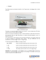
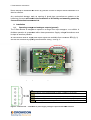
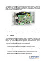
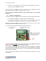
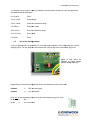
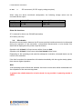
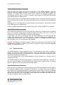
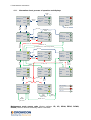
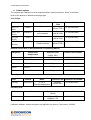
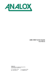
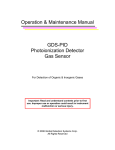
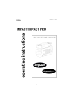
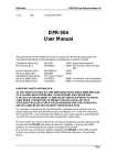
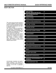
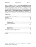
Crowcon F-Gas Detector
Infra-Red SF6 and Refrigerant Gas Detector
Installation, Operating and Maintenance Instructions
M070029
Issue 1
January 2014
F-Gas Detector Instructions
Table of contents
1.
General.......................................................................................................................... 3
2.
Installation...................................................................................................................... 4
3.
4.
2.1.
Operating voltage and analogue outputs (general) ................................................. 4
2.2.
Installation .............................................................................................................. 5
2.3.
Compensation of the ambient pressure................................................................... 7
Start-up.......................................................................................................................... 7
3.1.
Wiring instructions................................................................................................... 7
3.2.
Analogue output: (0)4-20mA ................................................................................... 8
3.3.
Use of the voltage output ........................................................................................ 9
3.4.
Wire breaks........................................................................................................... 10
Operating the transmitter using the key-pad................................................................. 11
4.1.
Start-up phase ...................................................................................................... 11
4.2.
Regular operation ................................................................................................. 12
4.3.
Malfunction ........................................................................................................... 12
4.4.
Device error / Hardware error ............................................................................... 12
4.5.
Maintenance ......................................................................................................... 12
4.6.
Exiting maintenance mode without accepting any changes................................... 12
4.7.
Exiting maintenance mode, taking over changes .................................................. 13
4.8.
Restoring factory settings...................................................................................... 13
4.9.
ZERO calibration .................................................................................................. 13
4.10.
SPAN-calibration ............................................................................................... 14
4.11.
Information sheet, process of operation and displays ........................................ 16
5.
Specifications............................................................................................................... 17
6.
Product options............................................................................................................ 18
7.
Warranty ...................................................................................................................... 19
The equipment described in this manual is designed for the detection of toxic gases.
Ensure local safety procedures are adopted before carrying out any maintenance or
calibration work.
The equipment described in this manual may be connected to remote alarms and/or
shutdown systems. Ensure that local operating procedures are adopted before
carrying out any maintenance or calibration work.
F-Gas
Gas Detector Instructions
1. General
The F-Gas detector provides the benefits of the IR gas sensor technology within a robust
enclosure.
Rear Casing
Interface PCB
Front Casing
Figure 1: F-Gas Detector Layout
The sturdy, IP54-protected
protected casing houses the IR sensor, a user interface with LED status
indication and the interface electronics (fig.1).
Based on the physical measuring principle of infrared absorption, apart from selectiveness,
this transmitter offers the best prerequisites for reliable and lasting detection
detection, even in a
difficult environment.
The F-Gas detector is able to detect even the smallest quantities of toxic gases reliably and
to report its findings to a connected control system. The gas concentration can be
transmitted as a linear analogue current or voltage output.
The following signals are available as analogue values:
(0)4 – 20mA
Linear; the desired operating mode can be set via a link
0 - 2V
Linear; the desired operating mode can be set via a link
0 - 5V
Linear; the desired operating mode can be set via a link
0 - 10V
10V setting requires at least 15V DC as supply voltage
Important: the F-Gas
Gas detector is not certified for use in a hazardous area. Any form of
maintenance, parameterization and all changes to the settings of the device must only be
carried out by trained and authorized staff.
F-Gas Detector Instructions
Never attempt to dismantle this device by yourself in order to tamper with its hardware or to
alter its software.
Any mechanical damage, such as opening of glued pipe connections or gaskets or the
loosening of screws will result in the termination of all liability and warranty granted by
Crowcon Detection Instruments Ltd.
2. Installation
2.1.
Operating voltage and analogue outputs (general)
The F-Gas detector is designed to operate in a range of an input voltage of 12 to 2
28Vdc. A
faultless operation is guaranteed within these parameters. Supply voltage fluctuations must
be kept as small as possible.
All connections used for supply and output signals are available from connector ST1 (fig. 2)
and can be accessed by opening the transmitter casing – see fig. 2.
Connector ST1
V+
I GND RS+ RS-
Figure 2: Opened transmitter casing with interface electronics
V+
I
Connection of the supply voltage 12 to 28Vdc.
Analogue output signal (optionally 0-20mA; 4- 20mA or 0 to 2/5/10V).
GND
0V (common ground for V+, I and RS485 (not yet implemented)
implemented)).
RS+
Non inverted signal line for the integrated RS485 interface (not yet implemented)
RS
RS-
Inverted signal line for the integrated RS485 interface (not yet implemented)
Figure 3: connector ST1 – connection for power supply, analogue output and the RS485 interface
F-Gas
Gas Detector Instructions
The connection of the internal IR sensor module to the interface electronics is via a 4
4-pin
data cable (Fig. 4). The
he circuit board is screwed to the internal built-in
built in casing from the
outside. The IR gas sensor is integrated into this casing to minimize the dead volume and to
protect it from any unwanted external effects.
Figure 4: 4-pin
pin data cable connecting the IR sensor to the interface PCB
Caution: The IR sensor module is tailored to the connected interface PCB and must only be
operated as a pair.. Both components form a fixed unit and must not be separated!
2.2.
Installation
The installation of the transmitter is described as follows.
The F-Gas
Gas detector should be mounted where the gas to be detected is most likely to be
present. The gas must come into direct contact with the sensor in order to be detected.
Detectors are typically
ypically installed around compressors, pressurised storage vessels,
refrigerant cylinders, within storage rooms or adjacent to pipelines. Gas leaks typically occur
from valves, pipe flanges and joints, pipe/vessel filling or draining connections, etc.
The following points should be noted when locating gas detectors:
• To detect heavier-than-air
air gases detectors should be mounted at low level.
• Detectors must be mounted as close as possible to potential leak sources.
• When locating detectors consider the possible damage caused by water: rain, flooding,
or exposure to jets from hoses or pressure washers.
• Consider ease of access for functional testing and servicing.
• Consider how the escaping gas may behave due to natural or forced air currents.
• Consider the process conditions. For example heavier than air gases may rise if
released from a process at elevated temperatures and/or pressures.
F-Gas Detector Instructions
The placement of sensors should be determined following advice of experts having specialist
knowledge of gas dispersion and the plant processing equipment as well as safety and
engineering issues. The agreement reached on the locations of sensors should be recorded.
Gently prize-open the flaps using a screw driver being careful to not damage the flaps (see
fig. 5):
Figure 5: Opening flaps to get access to the internal parts of the transmitter
Remove the front casing (fig. 6)
Figure 6: front casing removed
F-Gas Detector Instructions
Mount device vertically to the wall using the 4 screw holes (fig. 7) with the cable gland
pointing downwards.
Figure 7: mounting
holes
Mounting hole spacing: 127.5mm x 62.5mm. Mounting hole diameter: 4mm.
Warning: never install the detector with the front panel facing upwards. Doing so may
lead to the IR sensor filter becoming blocked by dust/contaminants which could
prevent gas from reaching the sensor.
2.3.
Compensation of the ambient pressure
In order for the transmitter to be as flexible as possible and to facilitate the use both at sea
level and in higher regions, the so-called real gas formula must be taken into account. As a
result of the physical properties of gases, the density will change, depending on the relevant
altitude and, due to this fact; the absorption of the IR radiation inside the measuring cell will
change accordingly. Without any pressure compensation, it would lead to inaccuracies in the
measurement of the concentration and possibly to faulty data.
As the ambient pressure must be taken into account when measuring the concentration in
diffusion mode, a pressure sensor is already integrated firmly in the transmitter.
For this reason no setting or parameterization by the user is required.
3. Start-up
3.1.
Wiring instructions
Electrical connections are made via the connector ST1 - see Figure 2.
In order to avoid any errors and damage, the system must be mounted while the power has
been switched off. It is imperative that the following order is observed:
1. Switch off the power.
2. Mount the transmitter in the desired position. While doing this, adequate distance to
live parts must remain in order to avoid short circuits and damage.
3. The installation in the vicinity of ventilators, windows, ventilation shafts and similar
facilities must be avoided. Any air flow or drought near the transmitter may lead to
inaccurate readings and false alarms or inadequate function.
F-Gas Detector Instructions
4. Connect a 3-core
core cable from the control system to the appropriate V+ (12-28Vdc) , I
(analogue
logue signal) and GND (0V) terminals.
The cross section of the cables used should not exceed 1.5mm². A compression type cable
gland is fitted suitable for cable with a maximum diameter of 5mm.
Crowcon strongly recomends installation using screened cables to avoid signal
interference.
3.2.
Analogue output: (0)4-20mA
(0)4
The analogue output of the transmitter offers
offer two options for reading out the measuring data:
1. Current signal in the region of 0-20mA,
0 20mA, linear to the measuring value;
2. Current signal in the region of 4-20mA,
20mA, linear to the measuring value. (This option
also facilitates the easy detection of a broken wire or the failure of the sensor)
(Alternatively,
Alternatively, the analogue output can be set as a voltage signal using links JP4, JP5, JP6. More
information regarding this can be found in sub-section
sub
3.3)
The mode of the current signal can be selected using the jumper JP3:
1. Not connected
0-20mA (factory settings)
2. Connected
4-20mA
Figure 8: Link JP3 for
selection of current mode (4
(420mA setting is shown)
Link JP3
Caution: switching between current modes with the link must only be carried out
when the power is turned off (disconnect supply voltage).
For the purpose of the analogue signal 0-20mA
0
or 4-20mA,
20mA, the transmitter can be regarded
as a Current Source transmitter. The F-Gas
Gas detector can be connected directly to a suitable
control system taking care to connect the V+, I and GND terminals to the ap
appropriate
connections on the controller.
Once the power supply has been connected, the transmitter becomes active and is running
(see chapter 5).
F-Gas
Gas Detector Instructions
The analog current output is able to indicate several different conditions. This complies with
the NAMUR NE43 standards:
0 to 2.8mA
Fault
3.2 to 3.6mA
Under-range
range
3.6 to 3.9mA
Under-run
run detection range
4 to 20mA
Detection range
20 to 21mA
Over-run
run detection range
21 to 21.5mA
Over-range
range
>21.5mA
Fault
3.3.
Use of the voltage output
In some applications it is necessary to read the output signals of the transmitter as a linear
voltage signal. For this purpose, the relevant link (JP4-6)
6) has to be connected (Figure 9).
Figure 9: Link JP4-6 for
selection of output voltage
(10V DC setting is shown
shown)
Depending on the selected operating mode, the following modes can be set:
0-20mA
JP3 not connected
4-20mA
JP3 connected
Only one of the following jumpers must be connected at any given time!
0..2V
JP4
0..5V
JP5 connected
F-Gas Detector Instructions
0..10V
JP6 connected (15V DC supply voltage required)
When using the above mentioned configuration, the following voltage values can be
connected at the output:
2V (JP4)
5V (JP5)
10V (JP6)
0-20mA (JP3 not connected)
0V – 2V
0V – 5V
0V – 10V
4-20mA (JP3 connected)
0.4 V – 2V
1.0V – 5V
2.0V – 10V
Other link functions:
JP1: reserved for future use (RS-485 termination)
JP2: factory use only.
3.4.
Wire breaks
Should the communication between the IR sensor and the interface electronics be disrupted
during the operation of the transmitter, (unintentional disconnection or wire break), this
status will be displayed at the power output as follows:
Operation with 4-20mA
Operation with 0-20mA
Output current will be frozen at 2mA.
the current value last issued will be frozen.
Depending on the operating mode and the subsequent evaluation, aforesaid status can be
used for error detection.
If the fault is repaired, the transmitter will restart automatically with the regular startup phase,
then resume regular operation.
Note:
If the operating mode 0-20mA was selected, the frozen current value will be maintained until
the completion of the new start-up phase.
In general, the reliable detection of a wire break is only possible in operating modes 420mA!
F-Gas Detector Instructions
4. Operating the transmitter using the key-pad
The control panel (figure 10) of the transmitter is integrated in the front cover. This is
required if zero or span calibration has to be carried out.
The following operating and display functions are available:
Display elements:
STATUS
STATUS-LED 3-colours (red, yellow, green)
SPAN-LED
LED yellow
ZERO-LED
LED yellow
SPAN
Operating elements:
UP
SPAN
ZERO
DOWN
button
button
button
button
ZERO
Figure 10: Display key-pad
The transmitter can be calibrated and several settings can be made using the display keypad.
3-colour STATUS-LED indicates the current operating status. Only one of the three colours
is active at any given time. In addition to this, the conditions “off“, ”on“ and ”flashing“ exist.
The SPAN and ZERO LEDs have a special purpose. At any given time, only one of these
two LEDs can be active. The three conditions “off“, ”on“ and ”flashing“ exist here as well.
4.1.
Start-up phase
After the power supply and the selected interfaces have been connected, the transmitter will
begin the start-up phase (STATUS-LED will flash green). This will take less than 2 minutes
and this time is used to check all internal components.
During the start-up phase, the analogue value issued shows the minimum value; the
concentration shows ”0“.
Depending on the operating mode selected, the following conditions can occur during the
start-up phase:
In 0-20mA mode
Output current 0mA. After approx. 2 minutes
depending on
the pending gas concentration. During the warm-up period, the sensor
signal may still deviate slightly from the exact concentration.
In 4-20mA mode
Output current approx. 2mA, then a jump to approx. 4mA. After about
sensor signal may show values of less than 4mA as it can still deviate
slightly from the exact concentration during the warm-up period.
Once the start-up phase is completed and all the test routines have been carried out with
positive results, the transmitter will change to its regular mode, making the measured gas
concentration available via the interfaces. In case a fault was detected during the start-up
phase, the transmitter will change to the operating mode “faulty” (see 4.3).
F-Gas Detector Instructions
4.2.
Regular operation
During regular operation, the STATUS-LED will show green throughout. The system is
operating faultlessly within its measuring parameters. The gas concentration values will be
indicated by the interface signal.
4.3.
Malfunction
Malfunction (STATUS-LED will flash red) is active if the concentration level is above or
below the defined limits to a degree that a violation of the measurement range has to be
considered.
This device status is reversible.
Once the concentration is back to its defined range, the STATUS-LED will automatically
change to green light (see “regular operation”).
4.4.
Device error / Hardware error
A device or hardware error (STATUS-LED lights up red without flashing) indicates
irreversible damage, which always requires a device service as in most cases the change or
repair of a component is necessary.
If still possible, an analogue value will be set, which indicates a fault
4.5.
Maintenance
Crowcon recommends the detector is zeroed and tested with gas every 12 months as a
minimum. The sensor may be zeroed in clean air, and the target gas must be applied at a
known concentration to verify correct sensor response.
Calibration gas should be applied using the Calibration Adaptor accessory (part number:
C03658) at a flow-rate of 0.5 litres per minute.
If internal settings are to be changed (e.g. calibration, parameters, factory settings,
addresses, access codes ) the system has to be switched to maintenance mode. A ZERO
or SPAN calibration for example is only possible after the maintenance mode has been
activated.
In case of a device error, the system cannot change to maintenance mode.
In order to get to maintenance mode, a pre-defined access code (factory settings: UP, UP,
SPAN, ZERO, DOWN, DOWN) must be entered faultlessly within 6 seconds.
Such an access code always consists of exactly 6 keystrokes, which must be entered one
after the other within 6 seconds.
If the access code is correct, the system will change to the first level of the maintenance
mode (STATUS-LED will light up yellow). If the access code is incorrect or not entered fast
enough, the STATUS-LED will signalize an error by flashing red for the second. In this case,
the maintenance mode will not be activated (the transmitter ill remain in regular or faulty
mode).
4.6.
Exiting maintenance mode without accepting any changes
If the maintenance mode should be exited without taking over any possibly carried out
changes, the button UP must be pressed for 3 seconds.
F-Gas Detector Instructions
The STATUS-LED will then change to signalization, flashing red for 3 seconds and the
change to “Regular operation” mode indicated by the STATUS-LED light up green.
Generally, maintenance mode will also be exited without taking over any changes if the user
has not made any entries for 30 minutes.
Caution: Maintenance mode can only be exited from level 1. An indication for level 1 is the
STATUS LED lighting up yellow (refer to diagram in section 4.11).
4.7.
Exiting maintenance mode, taking over changes
If maintenance mode should be exited, taking over all changes, the button DOWN should be
pressed for 3 seconds.
DOWN to be pressed for 3 seconds.
The STATUS-LED will then change to flashing green to signalize this and after that change
to “Regular operation” mode with the STATUS-LED light up green.
Caution: maintenance mode can only be exited from level 1. An indicator for level 1 is that
the STATUS-LED lights up yellow (refer to diagram in section 4.11).
4.8.
Restoring factory settings
This function deletes any previously made changes carried out by the user and restores the
factory settings of the transmitter. The module addresses, as well as the calibrated values
are not affected by this.
Press DOWN 6 times in a row for 6 seconds without any errors.
If the restoration has been completed successfully, the STATUS-LED will flash green for 3
seconds, then changing to lighting up yellow (one is still in level 1 of maintenance mode) one
is still able to carry out more system changes.
If an error is detected in the entering of the data, the STATUS-LED will flash red for 3
seconds, then changing to light up yellow (one is still in level 1 of maintenance mode). The
factory settings have not been restored. The process has to be repeated.
Caution: The changes only become effective when the maintenance mode has been exited
as described in chapter 5.1.7. Without this process, for instance when severing the operating
voltage, all changes will be lost.
4.9.
ZERO calibration
ZERO-calibration can only be carried out from level 1 of the maintenance mode being a selfcontained process (refer to diagram in section 4.11). For this reason, any new data collected
from the ZERO-calibration must be taken over or deleted explicitly when exiting the entire
maintenance mode (see Chapter 4.7).
The self-contained part of the ZERO-calibration is similar to a second level in the
maintenance mode.
The ZERO-calibration mode can be activated by pressing the button ZERO for 3 seconds. If
the entry was correct, the STATUS-LED will change from lighting up yellow to flashing
yellow. In addition to this, the ZERO-LED will flash yellow.
F-Gas Detector Instructions
Keep the ZERO pressed for 3 seconds.
Now, the user must apply the correct sample gas for the ZERO-calibration using the
available calibration adapter (typically air or nitrogen. In case of doubt, please contact the
supplier). If a stable value is found within a time window (60 seconds) regarding the
concentration and this value is found in a plausible value range, the ZERO-LED will change
from flashing yellow to steady yellow.
Now, the user is able to set the desired concentration value of the output signal by using the
UP and DOWN keys. For this, the relevant set value can be monitored live at the analogue
output.
Pressing the UP or DOWN keys for longer will lead to an auto-repeat. This feature is helpful
for the adjustment for a larger range.
Exiting the ZERO-calibration can be carried out any time by pressing ZERO for 3 seconds.
Keep ZERO pressed for 3 seconds.
If the action was successful, the STATUS-LED will change from flashing yellow to flashing
green for 3 seconds, subsequently changing to lighting up yellow (one is still in level 1 of
maintenance mode and is still able to carry out system change
In the case of an error in connection with the ZERO-calibration, the STATUS-LED will
change from flashing yellow to flashing red for 3 seconds, subsequently changing to a
steady yellow (one is still in level 1 of maintenance mode). The changed calibration values
were not taken over. This process has to be repeated.
Caution: The changes only become effective when the maintenance mode has been exited
as described in chapter 4.7. Without this process, for instance when severing the operating
voltage, all changes will be lost.
4.10.
SPAN-calibration
The SPAN-calibration is only possible from level 1 of maintenance mode (refer to diagram in
section 4.11); this is a self-contained process. Thus, even new data, which have been
gained from SPAN-calibration must be taken over or deleted explicitly when exiting the entire
maintenance mode (see Chapter 4.7).
The self-contained part of the SPAN-calibration can be regarded as a second level of
maintenance mode.
The SPAN-calibration level can be activated for 3 seconds by typing SPAN for 3 seconds. If
the entry was successful, the STATUS-LED will change from a steady yellow to flashing
yellow. In addition to this, the SPAN-LED will flash yellow.
Keep SPAN pressed for 3 seconds.
Now, the user must supply the correct sample gas for the SPAN-calibration with the help of
the calibration adapter, which is available as accessory. If a stable value is found within a
time window (60 seconds) regarding the concentration and this value is found in a plausible
value range, the SPAN-LED will change from flashing yellow to steady yellow within a time
window of 60 seconds. If the concentration found continues to be stable, the SPAN-LED will
change from flashing yellow to steady yellow.
F-Gas Detector Instructions
Now, the user is able to set the desired concentration value of the output signal by using the
UP and DOWN keys. For this, the relevant set value can be monitored live at the analogue
output.
Pressing the UP or DOWN keys for longer will lead to an auto-repeat. This feature is helpful
for the adjustment for a larger range.
It is possible to exit the SPAN-calibration at any time by pressing SPAN for 3 seconds.
Keep SPAN pressed for 3 seconds.
If the action was successful, the STATUS-LED will change from flashing yellow to flashing
green for 3 seconds, subsequently changing to lighting up yellow (one is still in level 1 of
maintenance mode and is still able to carry out system changes.
In the case of an error in connection with the SPAN-calibration, the STATUS-LED will
change from flashing yellow to flashing red for 3 seconds, subsequently changing to a
steady yellow (one is still in level 1 of maintenance mode). The changed calibration values
were not taken over. This process has to be repeated.
Caution: The changes only become effective when the maintenance mode has been exited
as described in chapter 4.7. Without this process, for instance when severing the operating
voltage, all changes will be lost.
F-Gas Detector Instructions
4.11.
Information sheet, process of operation and displays
Power
ON
STAT
STAT
Measur e:
SPAN
Out of
Range
St ar t up:
Sensor SPAN
scan
Sensor
found
ZERO
ZERO
SPAN
ZERO
3 s lat er
no key for
3 0 min
STAT
Measur e:
Sensor SPAN
okay
STAT
Sensor
br oken
Out of
r ange
Sensor
okay
ZERO
Failur e:
Sensor
br oken
STAT
3s
lat er
PIN er r . /
t imeout
STAT
Exit 1 :
Discar d SPAN
changes
Exit 1 :
Apply all SPAN
changes
ZERO
ZERO
PIN code
cor r ect
UP for 3s
DOWN for 3 s
6 x DOWN in 6 s: r ead fact or y default
3 s lat er
STAT
Ser vice:
SPAN
Basic
Level 1
ZERO
STAT
3 s
lat er
key er r . /
t imeout
STAT
Exit 2 :
Discar d SPAN
change
Exit 2 :
r egist er SPAN
change
ZERO
ZERO
6 x key
in 6 s is
new PIN
SPAN
for 3 s
key er r . /
t imeout
6 x UP in 6 s
ZERO
for 3 s
STAT
STAT
Ser vice:
SPAN
SPAN
scan
STAT
ZERO
UP /
DOWN:
gain t une
Ser vice:
SPAN
new
PIN
ZERO
any key
any key
ZERO
SPAN
ZERO
value
st able
value
st able
ZERO
Ser vice:
SPAN
SPAN
st able
STAT
Ser vice:
SPAN
ZERO
scan
STAT
LED flashing:
Ser vice:
SPAN
ZERO
st able
LED on:
ZERO
UP /
DOWN:
offset t une
LED off:
ZERO
for 3 s
SPAN for 3 s
Maintenance mode access code (factory settings: UP, UP, SPAN, ZERO, DOWN,
DOWN). Must be entered faultlessly within 6 seconds.
F-Gas Detector Instructions
5. Specifications
Measuring Principle:
Non-dispersive infrared (NDIR)
Range:
0-1000ppm
Resolution:
1ppm
Start-up time:
<120 seconds
Size:
151 x 80* x 60mm (W x H x D)
*Total width with cable gland: 102mm
Weight:
0.25Kg
Ingress Protection:
IP54
Power:
12-28Vdc
Analogue Output:
4-20mA current source (can also be set to 0-20mA, 0-2V,
0-5V, 0-10V)
Repeatability:
+/-1% of full-scale
Linearity:
+/-2% of full-scale
Operating Temperature:
-20°C to +40°C
Humidity:
0-95%RH (non-condensing
Pressure:
800 – 1200mBar
Response Time:
30 seconds (approximately)
Approvals:
EMC: EN50270
This product is designed for non-hazardous area operation only.
F-Gas Detector Instructions
6. Product options
The required gas calibration must be stipulated when ordering a detector. Refer to the labels
fixed to the detector to determine the target gas.
Pure Fluids:
Fluids
Formula
Name
Exposure
Limit
Detector Part Number
HCFC 22
(R22)
CHClF2
Chlorodifluoromethane
1000ppm
(EH40, STEL)
T2-700105-03002
HCFC 123
(R123)
CHCl2CF3
2,2-Dichloro-1,1,1trifluoroethane
50ppm
(OSHA, PEL)
T2-730105-03002
HFC 125
(R125)
C2HF5
Pentafluoroethane
1000ppm
(OSHA, PEL)
T2-720105-03001
HFC 134a
(R134a)
CH2FCF3
1,1,1,2Tetrafluoroethane
1000ppm
(EH40, STEL)
T2-710105-03003
Blended Fluids Used in Refrigeration/Air Conditioning Market:
Refrigerant
Composition
Components
Exposure Limit
Detector Part Number
(OSHA, PEL)
R404a
R407a
R143a/125/134a
R32/125/134a
1000ppm
1000ppm
T2-740105-03001
T2-750105-03001
R407c
R32/125/134a
1000ppm
T2-800105-03001
R410a
R32/125
1000ppm
T2-760105-03001
R507
R143a/125
1000ppm
T2-770105-03001
Speciality fluids:
Fluid
R1234yf
Formula
Name
Exposure Limit
CH2=CFCF3
2,3,3,3Tetrafluoropropene
500ppm
(OSHA, PEL)
Detector Part Number
T2-780105-03001
Insulating Gas:
Gas
Name
Exposure Limit
(EH40)
Detector Part Number
SF6
Sulphur Hexaflouride
1000ppm STEL
1250ppm LTEL
T2-600105-00006
Accessories:
Calibration adaptor: enables test gas to be applied to the sensor. Part number: C03658.
F-Gas Detector Instructions
7. Warranty
This equipment leaves our works fully tested and calibrated. If within the warranty period (1
year), the equipment is proved to be defective by reason of faulty workmanship or material,
we undertake at our discretion either to repair or replace it free of charge, subject to the
conditions below.
Warranty Procedure
To facilitate efficient processing of any claim, contact our customer support team on 01235
557711 with the following information:
Your contact name, phone number, fax number and email address.
Description and quantity of goods being returned, including any accessories.
Instrument serial number(s).
Reason for return.
Obtain a Returns form for identification and traceability purpose. This form may be
downloaded from our website ‘crowconsupport.com’, along with a returns label, alternatively
we can ‘email’ you a copy.
Instruments will not be accepted for warranty without a Crowcon Returns Number
(“CRN”). It is essential that the address label is securely attached to the outer
packaging of the returned goods.
Units returned to Crowcon as faulty and are subsequently found to be ‘fault free’ or requiring
service, may be subject to a handling and carriage charge.
Warranty Disclaimer
The guarantee will be rendered invalid if the instrument is found to have been altered,
modified, dismantled, or tampered with. Any service by 3rd parties not authorized & certified
by Crowcon will invalidate the warranty on the equipment. Use of alternative manufacturer’s
sensors which have not been approved by Crowcon will invalidate the warranty of the
product as a whole. The warranty does not cover misuse or abuse of the unit.
Sensor types have individually defined warranty periods which can differ from the hardware
warranty period. Crowcon reserve the right to amend warranty periods for particular
applications. Sensor warranty is rendered invalid if the sensors have been exposed to
excessive concentrations of gas, extended periods of exposure to gas or have been
exposed to ‘poisons’ that can damage the sensor, such as those emitted by aerosol sprays.
F-Gas Detector Instructions
Crowcon Regional Addresses