1
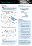
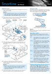
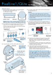
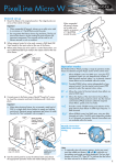
PixelLine2·4·6 Version 1.64 firmware User Manual General set up 1 Mount the fixture in the required position. The integral yoke can act as a floor stand or hanger. Important Using the yoke The PixelLine yoke has an adjustable foot at each end to allow it to function as an effective floor stand or be folded away to allow multiple units to be closely stacked. • When suspended off ground, always use two independent fixing points. Also always use two safety wires rated to a minimum of 40kg (88lbs) SL6, 30Kg (66lbs) SL4 or 15Kg (33lbs) SL2 around the yoke. Yoke folded flat 2 Where external control is to be used, connect a DMX lead (XLR 5-pin female) to the input socket at the rear of the fixture. DMX in (XLR 5pin male) connector Power in socket Connector required: Neutrik® PowerCon® (NAC3FCA) Yoke feet extended for use as a floor stand Important Please see the warning on page 7 regarding the stacking of PixelLine fixtures. Operation modes The PixelLine provides a range of operation modes. These are selected using the MODE section of the control menu: Yoke foot locking knob 3 Where other fixtures are to be used in a control daisy-chain, connect a DMX lead (XLR 5-pin male) to the output socket at the rear of the fixture. Power out socket Connector required: Neutrik® PowerCon® (NAC3FCB) DMX out (XLR 5pin female) connector 4 Connect power to the fixture using a Neutrik® PowerCon® connector. Insert the connector and twist it clockwise until it clicks into place. Important • If power daisy-chaining fixtures, do not exceed a total load of 3kW in a single daisy chain (subject to supply and cabling restrictions). Please see page 7 for maximum power requirements per fixture and also ‘Start up (peak)’ details. 5 Use the control panel to access the internal menu and choose the appropriate operation mode and related settings (see over). DMX Allows RGBW control via DMX input. Internal chase effects are not available within this mode. MANU Provides RGBW colour mixing independently of any external control. Use the internal control menu (MAN section) to select the required colour values. EF M Allows the display of the dual internal chase effects, independently of any external control. Use the internal control menu (PROG section) to select the required chase effects, speeds and cross fades. 24+E 16+E 8+E Provides control of individual emitter RGBW mixing and selection of the dual internal chase effects via DMX input. Requires 32 (PL6), 24 (PL4) or 12 (PL2) DMX channels. 4+E Provides control of RGBW mixing and selection of the dual internal chase effects via DMX input. Requires 11 DMX channels. 16bt Allows RGBW control via DMX input, using two 8bit channels per colour. Internal chase effects are not available within this mode. PixelLine personalities are available for a variety of controllers. Please see www.pixelrange.com for details. Factory reset (perform this prior to new use) To clear previous settings: At the rear panel, press the middle two buttons ( and ) for two seconds while the current address and mode are being displayed. The four digit display will show FACT then SET to indicate that the fixture has been returned to its default condition. This is useful to remove any settings that might cause confusion in a new configuration (e.g. master intensity settings). 1 General notes Using the menu • Ensure that only one DMX • When not in the menu, the four digit display scrolls the device in the chain is set as master (e.g. the lighting desk). This fixture is usually set to slave mode. •This fixture is shipped with the DMX address set to 001. •The four digit display can be set to switch off when not in use. To restore, press . To alter this mode use: PERS > DISP. current DMX address and mode. The display’s right hand decimal point (data dot) is used to indicate status (see below). MENU ENTER DOWN •Press to enter the menu. The four digit display will show ADDR. •Use and to move between menu options (or to change a value within an option). UP •Press to enter an option (or to fix a changed value within an option and return to the previous option level). Note: If you do not press to fix a value, operation will revert to the previously set mode at the next power on. www.pixelrange.com *Refer to product manual for proper operating instructions •Press to exit from a menu option (and eventually exit the menu completely). Chase effects Master/slave/data indication This section describes each of the internal chase effects that are selectable either via the control menu (PROG > C1/C2 > EFEC) or using DMX values sent from an external source. To use the internal effects, set the MODE option either to EF M (for internal menu control) or 4+E, 5+E or 61+E (for external DMX control). The right hand decimal point (data dot) of the display is used to indicate the master/slave settings and also the presence of a DMX input signal, as shown below: DMX EFEC Chase effect description valuevalue 0-3 00Off 4-7 01 Rainbow forward chase (6 cell) 8-11 02 Rainbow reverse chase (6 cell) 12-15 03 Cool white forward chase (6 cell) 16-19 04 Cool white reverse chase (6) 20-23 05 Cool white outer/inner/outer chase 24-27 06 50/50 duty cycle cool white strobe 28-31 07 50/50 duty cycle red strobe 32-35 08 50/50 duty cycle purple strobe 36-39 09 50/50 duty cycle yellow strobe 40-43 10 50/50 duty cycle green strobe 44-47 11 Pulse white strobe 48-51 12 Pulse light blue strobe 52-55 13 Pulse rainbow strobe 56-59 14 Pulse red/green/blue strobe 60-63 15 Rainbow forward strobe (cells together) 64-67 16 Rainbow reverse strobe (cells together) 68-71 17 Yellow/blue strobe (cells together) 72-75 18 Horizontal split rainbow chase 76-79 19 6 cell yellow/blue chase 80-83 20 6 cell red/blue chase 84-87 21 3 cell red/yellow chase 88-91 22 3 cell RGB forward chase 92-95 23 3 cell rainbow forward chase 96-99 24 3 cell RGB reverse chase 100-103 25 Static salmon pink 104-107 26 Static yellow 108-111 27 Static light blue 112-115 28 Static purple 116-119 29 Static red 120-123 30 Static green 124-127 31 Static cool white [These are not yet confirmed] Data dot ON Master mode Data dot FLASHING Slave mode (DMX data input present) Data dot OFF Slave mode (no DMX data present) Notes: • Ensure that only one DMX device in the chain is set as master (e.g. the desk). • Use PERS > data to change between master and slave modes. • When set to master mode, the fixture will scroll MASTER in place of a DMX address (when not within the menu). • If the display has been set to auto off (disp > aoff), the data dot will remain active but at a lower brightness. DMX links and termination This section provides useful advice for gaining reliable operation from your DMX installation: • Use good quality flexible twisted pair cable that has a nominal characteristic impedance of 120 ohms. Microphone cables have a lower impedance and a higher capacitance, which can lead to data errors. • Use a daisychain arrangement to link fixtures together, so that the output of one fixture is connected to the input of the next. • Connect no more than 32 devices to a single DMX run. If further fixtures are needed, then use a DMX booster to allow up to 32 more fixtures to be attached. • Never split a DMX cable to form two branches (a Y-split). If separate branches are required, use a powered DMX splitter. • Ensure that the devices at each end of the daisychain are both terminated using a 120 ohm resistor (usually contained within a separate XLR connector that has no cable - the resistor forms a link between pins 2 and 3). Control desks are usually internally terminated. It is possible to get away with breaking some of the above rules, particularly on smaller installations that have short cable runs and few fixtures. However, results can be unpredictable and problems will inevitably hit you at the very worst time: During your show. Please see the ‘Troubleshooting’ section for useful fault finding tips. 2 Control menu contents Shows the main processor software revision. No changes are possible within this option. Press while viewing this option to see the software sub-revision. Shows the display controller software revision. No changes are possible within this option. Selects the primary internal chase effect. See Chase effects for descriptions. Select MODE > EF M to show the selected chase. Selects the cross fade speed between the steps of the selected C1 chase effect. Selects the speed of the selected C1 chase effect. Selects the master intensity level of chase effects C1 and C2. Selects the secondary internal chase effect. See Chase effects for descriptions. Select MODE > EF M to show the selected chase. Selects the cross fade speed between the steps of the selected C2 chase effect. Selects the speed of the selected C2 chase effect. Sets the red intensity. Select MODE > MANU (manual) to show the result. Sets the green intensity. Select MODE > MANU (manual) to show the result. Sets the blue intensity. Select MODE > MANU (manual) to show the result. Sets the white intensity. Select MODE > MANU (manual) to show the result. Selects number of channels required to control all emitters. Options are 3, 4, 6, 8*, 9*, 12*, 18 or 24. Emitters are grouped together accordingly. * Only on some models. Determines whether this fixture will act as a master controlling others. When controlled via DMX this fixture must be set to SLAV. DMX and 16bt modes only. When set ON this enables the master intensity channel. The master intensity is always 16bit. For 8bit control use the high (initial) mint channel. When set oN, this option scrolls through the primary colours at power on to demonstrate correct operation of the emitters. Sets the base DMX address from which the control channels will begin. Determines the intensity of the four digit control panel display. Values range from 0 (dimmest) to 15 (brightest). When set to AOFF, the control panel display will blank out 60 seconds after the menu is exited. The data dot indicator will remain active. Provides a choice of two dimmer curves (FINE or TUNG) to suit particular circumstances. See next page for descriptions of each option. RGBW control using an external DMX control input. PERS > MINT set to ON provides a master intensity in DMX and 16bt modes. No chase effects are selectable. Displays the resulting RGBW levels that are set via the MAN section of the internal menu. External DMX control is not possible in this mode. Displays the chase effect(s) determined within the PROG section. External DMX control is not possible in this mode. PixelLine6 only DMX Ch1 to 24: RGBW colour mixing, Ch25 to 27: C1 Effect, Speed & Xfade, Ch28 to 30: C2 Effect, Speed & Xfade, Ch31 to 32: Master intensity (16 bit). PixelLine4 only DMX Ch1 to 16: RGBW colour mixing, Ch17 to 19: C1 Effect, Speed & Xfade, Ch20 to 22: C2 Effect, Speed & Xfade, Ch23 to 24: Master intensity (16bit). PixelLine2 only DMX Ch1 to 8: RGBW colour mixing, Ch9 to 11: C1 Effect, Speed & Xfade, Ch12 to 14: C2 Effect, Speed & Xfade, Ch15 to 16: Master intensity (16bit). DMX Ch1 to 4: RGBW colour mixing, Ch5 to 7: C1 Effect, Speed & Xfade, Ch8 to 10: C2 Effect, Speed & Xfade, Ch11 to 12: Master intensity (16bit). 16bit RGBW control using 2x the number of DMX channels determined by PERS>RES. PERS>MINT set to On provides a master intensity. No chase effects are selectable. Menu contents are not yet confirmed 3 Channel layouts for remote effects modes Channel layouts for DMX mode on PixelLine2 The table below shows how colour mixing, chase effects, master intensity and dimmer select controls are mapped to DMX channels for the 4+E, 5+E and 61+E modes. In all modes, the first channel of the fixture occurs at the DMX address selected using addr and successive channels for the fixture follow from there. When using DMX mode, the manner in which LED emitters are assigned to DMX channels is directly determined by the PERS > RES option. The dmx mode does not use chase effects. The first channel of the fixture occurs at the DMX address selected using addr and successive channels for the fixture follow from there. Channel Channel dmX dmx) dmx dmx (RES=3)(RES=4)(RES=6)(RES=8) 1 R (all cells) R (all cells) R (cell A) R (cell A) 2 G (all cells) G (all cells) G (cell A) G (cell A) 3 B (all cells) B (all cells) B (cell A) B (cell A) 4 Mast. int. (c)* W (all cells) R (cell A) W (cell A) 5 Mast. Int. (f)* Mast. int. (c)* G (cell A) R (cell B) 6 Mast. Int. (f)* B (cell A) G (cell B) 7 Mast. int. (c)* B (cell B) 8 Mast. Int. (f)* W (cell B) 9 Mast. int. (c)* 10 Mast. Int. (f)* 4+E 8+E 1 R (all cells) 2 G (all cells) 3 B (all cells) 4 W (all cells) 5 c1 Effect 6 c1 Speed 7 c1 Xfade 8 c2 Effect 9 c2 Speed 10 c2 Xfade 11 Master int.(c) 12 Master int.(f) 13 All models 14 R (cell A) G (cell A) B (cell A) W (cell A) R (cell B) G (cell B) B (cell B) W (cell B) c1 Effect c1 Speed c1 Xfade c2 Effect c2 Speed c2 Xfade 15 Master int.(c) 16 Master int.(f) 17 PixelLine2 18 only 19 20 21 22 23 24 25 26 27 28 29 30 31 32 16+E 24+E R (cell A) R (cell A) G (cell A) G (cell A) B (cell A) B (cell A) W (cell A) W (cell A) R (cell B) R (cell B) G (cell B G (cell B B (cell B) B (cell B) W (cell B) W (cell B) R (cell C) R (cell C) G (cell C) G (cell C) B (cell C) B (cell C) W (cell C) W (cell C) R (cell D) R (cell D) G (cell D) G (cell D) B (cell D) B (cell D) W (cell D) W (cell D) c1 Effect R (cell E) c1 Speed G (cell E) c1 Xfade B (cell E) c2 Effect W (cell E) c2 Speed R (cell F) c2 Xfade G (cell F) Master int.(c) B (cell F) Master int.(f) W (cell F) c1 Effect PixelLine4 c1 Speed only c1 Xfade c2 Effect c2 Speed c2 Xfade Master int.(c) Master int.(f) ( c) = Coarse or high channel, (f) = Fine or low channel. For 8-bit master intensity control, use the high (coarse) intensity channel. 4 cell F ( c) = Coarse or high channel, (f) = Fine or low channel. For 8-bit master intensity control, use the high (coarse) intensity channel. PixelLine6 only Cell locations PixelLine6 > * The 16-bit master intensity channels are enabled only when the pers > mint option is set to on. For 8-bit master intensity control, use the high (coarse) intensity channel. PixelLine2 > cell B cell A PixelLine4 > cell D cell C cell B cell A cell E cell D cell C cell B cell A Channel layouts for DMX mode on PixelLine4 When using DMX mode, the manner in which LED emitters are assigned to DMX channels is directly determined by the PERS > RES option. The dmx mode does not use chase effects. The first channel of the fixture occurs at the DMX address selected using addr and successive channels for the fixture follow from there. Channel dmX dmx) dmx dmx dmx dmx (RES=3)(RES=4)(RES=6)(RES=8)(RES=12)(RES=16) 1 R (all cells) R (all cells) R (cells A+B) R (cells A+B) R (cell A) R (cell A) 2 G (all cells) G (all cells) G (cells A+B) G (cells A+B) G (cell A) G (cell A) 3 B (all cells) B (all cells) B (cells A+B) B (cells A+B) B (cell A) B (cell A) 4 Mast. int. (c)* W (all cells) R (cell C+D) W (cells A+B) R (cell B) W (cell A) 5 Mast. Int. (f)* Mast. int. (c)* G (cell C+D) R (cells C+D) G (cell B) R (cell B) 6 Mast. Int. (f)* B (cell C+D) G (cells C+D) B (cell B) G (cell B) 7 Mast. int. (c)* B (cells C+D) R (cell C) B (cell B) 8 Mast. Int. (f)* W (cells C+D) G (cell C) W (cell B) 9 Mast. int. (c)* B (cell C) R (cell C) 10 Mast. Int. (f)* R (cell D) G (cell C) 11 G (cell D) B (cell C) 12 B (cell D) W (cell C) 13 Mast. int. (c)* R (cell D) 14 Mast. Int. (f)* G (cell D) 15 B (cell D) 16 W (cell D) 17 Mast. int. (c)* 18 Mast. Int. (f)* * The 16-bit master intensity channels are enabled only when the pers > mint option is set to on. For 8-bit master intensity control, use the high (coarse) intensity channel. ( c) = Coarse or high channel, (f) = Fine or low channel. For 8-bit master intensity control, use the high (coarse) intensity channel. Channel layouts for DMX mode on PixelLine6 When using DMX mode, the manner in which LED emitters are assigned to DMX channels is directly determined by the PERS > RES option. The dmx mode does not use chase effects. The first channel of the fixture occurs at the DMX address selected using addr and successive channels for the fixture follow from there. Channel dmX dmx) dmx dmx DMX dmx dmx dmx (RES=3)(RES=4)(RES=6)(RES=8)(RES=9)(RES=12)(RES=18)(RES=24) 1 R (all cells) R (all cells) R (cells A+B+C) R (cells A+B+C) R (cells A+B) R (cells A+B) R (cell A) R (cell A) 2 G (all cells) G (all cells) G (cells A+B+C) G (cells A+B+C) G (cells A+B) G (cells A+B) G (cell A) G (cell A) 3 B (all cells) B (all cells) B (cells A+B+C) B (cells A+B+C) B (cells A+B) B (cells A+B) B (cell A) B (cell A) 4 Mast. int. (c)* W (all cells) R (cells D+E+F) W (cells A+B+C) R (cells C+D) W (cells A+B) R (cell B) W (cell A) 5 Mast. Int. (f)* Mast. int. (c)* G (cells D+E+F) R (cells D+E+F) G (cells C+D) R (cells C+D) G (cell B) R (cell B) 6 Mast. Int. (f)* B (cells D+E+F) G (cells D+E+F) B (cells C+D) C (cells C+D) B (cell B) G (cell B) 7 Mast. int. (c)* B (cells D+E+F) R (cells E+F) B (cells C+D) R (cell C) B (cell B) 8 Mast. Int. (f)* W (cells D+E+F) G (cells E+F) W (cells C+D) G (cell C) W (cell B) 9 Mast. int. (c)* B (cells E+F) R (cells E+F) B (cell C) R (cell C) 10 Mast. Int. (f)* Mast. int. (c)* G (cells E+F) R (cell D) G (cell C) 11 Mast. Int. (f)* B (cells E+F) G (cell D) B (cell C) 12 W (cells E+F) B (cell D) W (cell C) 13 Mast. int. (c)* R (cell E) R (cell D) 14 Mast. Int. (f)* G (cell E) G (cell D) 15 B (cell E) B (cell D) 16 R (cell F) W (cell D) 17 G (cell F) R (cell E) 18 B (cell F) G (cell E) 19 Mast. int. (c)* B (cell E) 20 Mast. Int. (f)* W (cell E) 21 R (cell F) 22 G (cell F) 23 B (cell F) 24 W (cell F) 25 Mast. int. (c)* 26 Mast. Int. (f)* DMX channel layouts checked on units 5 Troubleshooting • Display panel is blank: Press a control panel button, if the display still does not show, check the input power and fuse. Fuse access The single fuse is located on the rear panel. Use a small flat blade screw driver to twist the fuse holder anti-clockwise until the carrier can be extracted to reveal the fuse. • No response during DMX control: Check whether a master intensity input is required. 4+E, 8+E, 16+E and , 24+E modes always require a master intensity input. DMX and 16bT have an optional master intensity, depending on the setting of PERS > MINT. If the MINT setting is On then no output will occur until a level greater than zero is applied to the master intensity channel(s). See pages 4 and 5 for details. Fuse types PixelLine2: 20mm 4A (T4AH250VP) time delay, ceramic body PixelLine4: 20mm ??A (T4AH250VP) time delay, ceramic body PixelLine6: 20mm 6.3A (T6.3AL250VP) time delay, ceramic body Note: It is good practice to perform a factory reset before these fixtures are used on any new installation. This will ensure that settings like the MINT option are set to off and do not create the potential for confusion. See page 1 for details of how to perform a factory reset. • No response during DMX control: If live DMX is connected, the right hand decimal point on the display should flash - if not, check the DMX cable(s) and the desk output. • Erratic operation during DMX control: Check that the final fixture within the DMX daisy chain is correctly terminated with a 120 ohm terminator plug. • Erratic operation during DMX control: Check that the selected MODE matches the personality being used on the control desk. • Erratic operation during DMX control: Ensure that only one DMX device in the daisy chain is set as master. • Rapid colour/intensity changes not occurring: Check whether the tungsten dimmer mode is selected (PERS > dIMR > TUNG). This would slow the reaction times of the emitters and could mean that rapid changes are blended into each other. Choose FINE for a faster reacting dimmer mode. • Standalone chase effects not working: Check that a chase has been programmed using PROG > C1 and/or PROG > C2 and also that MODE > EF M is selected. Check also that PROG > LEVL is not set at zero. • Standalone RGBW mixing not working: Check that one or more colour values have been set within MAN section and also that the MODE > MANU is selected. Using master mode to drive other units This unit can control any number of other PixelRange fixtures via DMX links, without the need for a control desk. 1 Set this unit as master (PERS > DATA > MAST) and ensure all others are set to slave (PERS > DATA > SLAV). Connect all fixtures via DMX daisy-chain. Note: Don’t forget to terminate the devices at either end of the chain - see the section ‘DMX links and termination’. 2 Set each slave to Mode > DMX. 3 Set the master to either create chases or static colours: Chases: Select Mode > EF m and then use PROG > C1 and C2 to create the required effects (see the ‘Chase effects’ table). Static colours: Select Mode > MANU and then use MAN > RED, GRN, BLUE and Whit to mix the colour. Firmware upgrades Firmware upgrades are released from time to time in order to provide new operational features. The PixelLine has been designed to allow straightforward firmware upgrading via its DMX interface, a PixelU2D USB device and a computer. Note: The setting of PERS > RES determines how the DMX channels are output when mixing static colours: PERS > RES=4 (or 96 or 144) sends out separate red, green, blue and white levels in repeated 4 channel blocks: i.e. 1 to 4, 25 to 28, etc. The RES=1 setting links all DMX output channels so that all emitters can be controlled by a single setting (MAN > Red). 4 Set each slave DMX address (using ADDR > DMX) as appropriate: •For static colour mixing you can either set all fixtures to DMX channel 1 or position them at the beginning of the four channel cells: A001, A025, A049, A073, A097 or A121. The outputs within each cell will be the same. •For chases, six separate cells are output in groups of 4 DMX channels to give RGBW values per cell. Set the address of each slave fixture according to which of the 6 cells you want them to appear within, or to begin with (for multi-cell fixtures): (A001 for cell A, A025 for cell B, A049 for cell C, A073 for cell D, A097 for cell E or A121 for cell F). Please contact PixelRange technical support for details. Master mode not fully checked on unit 6 Specifications Dimensions 25 50 1835 (SmartLine6) 50 1220 (SmartLine4) 610 (SmartLine2) Dimensions not fully checked on units 205 265 63 Weight Fixture and yoke: approx. 16kg (35.3 lbs) approx. 12kg (26.5 lbs) approx. 6kg (13.2 lbs) (PixelLine6) (PixelLine4) (PixelLine2) Important Power Input voltage: 100 to 240V AC, 47 to 63Hz autosensing Earth leakage 0.39mA? Connectors: Supplied with cable only: live, neutral & earth Power requirements: @ 230V/50Hz @ 115V/60Hz Standby 3 watts 3 watts Maximum (const.) Maximum (const.) 330 watts 220 watts 330 watts 220 watts Start up (peak*) ?? amps ?? amps If closely stacking PixelLine units, it is important to reduce the output intensity to no more than 30% of the maximum, in order to prevent overheating. The PixelLine units are equipped with heat sensors throughout their circuitry to ensure protection. The units will begin to reduce output automatically (in stages) once the internal temperature exceeds 600C. (PixelLine6) (PixelLine4) * The peak value occurs only at first power up and lasts only for a period measured in microseconds. Approvals Miscellaneous Enclosure rating: IP20 (not protected against moisture ingress) Control input: USITT DMX512 (input connector pin out below) PIN 1 PIN 5 Ground Not used PIN 2 PIN 4 Data – PIN 3 Not used Data + Documentation by Corporate Text & Design (www.ctxd.com) Release DRAFT a UK +44 (0)1905 363600 [email protected] www.pixelrange.com USA +1 865 675 3955 [email protected] 7