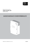
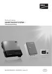
1
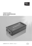
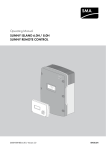
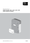
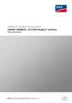
SUNNY BACKUP-SET S
Integration of a backup system into a PV plant, designed according to the
"Internal consumption of solar power" principle (Section 33, Para. 2 EEG 2009)
This document is valid for a Sunny Backup-Set S with an SBU 2200 from firmware version 1.3 and
with an Automatic Switch Box S (AS-Box-S.1).
This documents covers the following topics:
• Increased self-consumption with a Sunny Backup system
• Integration of the loads into increased self-consumption and backup function
• Arrangement of the energy meters and PV inverters in a Sunny Backup system
• Information on the installation of a neutral conductor
• Redundant earthing of the Sunny Backup 2200
• Configuring the Sunny Backup 2200 for increased self-consumption
• Parameters for increased self-consumption in the Sunny Backup 2200
1 Increased Self-Consumption
You can increase self-consumption by buffering the PV energy with a Sunny Backup system. In a
Sunny Backup system with increased self-consumption, the Sunny Backup retrieves the data from the
connected energy meters via the Sunny Home Manager, and uses it to determine the PV production,
feed-in and purchased electricity. Alternatively, you can use a Meter Box for Sunny Backup for
retrieving energy meter data.
SBU2200_Eigv-TB-en-12 | DBEN-SBU22_EIGV | Version 1.2
EN
2 Integration of the Loads into Increased Self-Consumption and Backup Function
SMA Solar Technology AG
2 Integration of the Loads into Increased
Self-Consumption and Backup Function
When installing the Sunny Backup system, you can connect single-phase loads to the energy supply
in two ways:
• between the combined feed-in and consumption meter and the Automatic Switch Box
or
• at the X4/Backup Loads terminal of the Automatic Switch Box
The number of line conductors and type of load connection influence the way in which the loads are
integrated into the increased self-consumption and backup functions, as shown in the table below.
2
Type of load connection
Integration into
increased
self-consumption
Supply of loads when
the electricity grid fails
Single--phase load at terminal
X4/Backup Loads of the AS-Box-S.1
Yes
Yes
Single--phase loads between feed-in
and consumption meter and
AS-Box-S.1 via L1
No
No
Single-phase loads between feed-in and No
consumption meter and
AS-Box-S.1 via L2/L3
No
Three--phase loads between feed-in and No
consumption meter and PV production
meter
No
SBU2200_Eigv-TB-en-12
Technical Description
SMA Solar Technology AG
3 Arrangement of the Energy Meters and PV Inverters in a Sunny Backup System
3 Arrangement of the Energy Meters and PV Inverters in
a Sunny Backup System
Figure 1:
Arrangement of the energy meters and PV inverters in a Sunny Backup system with a single-phase
PV inverter
Technical Description
SBU2200_Eigv-TB-en-12
3
3 Arrangement of the Energy Meters and PV Inverters in a Sunny Backup System
Figure 2:
4
SMA Solar Technology AG
Arrangement of the energy meters and PV inverters in a Sunny Backup system with a three-phase
PV inverter
SBU2200_Eigv-TB-en-12
Technical Description
SMA Solar Technology AG
4 Installing the Neutral Conductor
4 Installing the Neutral Conductor
When installing the Sunny Backup system, you need to make sure that the PV plant's neutral conductor
is always led through the Automatic Switch Box at terminal X2/PV-System. This will prevent the
Sunny Backup 2200 from switching off due to asymmetric currents within the Automatic Switch Box.
5 Redundant Earthing
The Sunny Backup 2200 requires redundant (double) earthing. This requirement is met if the plant
is installed according to the "grid feed-in of solar power" principle.
If installation is being carried out according to the "internal consumption of solar power" principle,
you have two options for providing redundant earthing.
Option 1: Redundant earthing is provided through type of cabling
Under option 1, the Sunny Backup 2200 is earthed once through the Automatic Switch Box and once
directly through a grounding cable (see Figure 3). Hence, redundant earthing is given.
Figure 3:
Sunny Backup system according to the "internal consumption of solar power" principle; redundant
earthing is provided.
Technical Description
SBU2200_Eigv-TB-en-12
5
5 Redundant Earthing
SMA Solar Technology AG
Option 2: Redundant earthing is provided through an additional protective conductor
from the main distribution
Under option 2, the connection between the electricity grid, the Automatic Switch Box and the
Sunny Backup 2200 is realised in an external enclosure.
This option does not provide redundant earthing. If you use this option, you need to earth the
Sunny Backup 2200 by means of a second protective conductor from the main distribution (see Figure
4). Alternatively, you can use just one protective conductor with cross-section ≥ 10 mm².
Figure 4:
6
Sunny Backup system according to the "internal consumption of solar power" principle; redundant
earthing is realised by additional protective conductor from the main distribution
SBU2200_Eigv-TB-en-12
Technical Description
SMA Solar Technology AG
6 Configuring the Sunny Backup 2200 for Increased Self-Consumption
6 Configuring the Sunny Backup 2200 for
Increased Self-Consumption
6.1 Activating or Deactivating the Increased Self-consumption
Function
There are two ways to activate or deactivate the increased self-consumption function:
• Activate or deactivate the increased self-consumption function in the Sunny Backup 2200
• Activate or deactivate the increased self-consumption function via Sunny WebBox
Activating or deactivating the increased self-consumption function in the
Sunny Backup 2200
1. Enter the installer password (see technical description of the Sunny Backup system).
2. Select the parameter 200# Settings > 230# Set Backup > 236# SlfCsmpInc >
01# SlfCsmpIncEna.
3. Carry out the desired setting.
Setting
Explanation
Enable
Activates the increased self-consumption function
Disable
Deactivates the increased self-consumption function
4. Save setting.
Activating or deactivating the increased self-consumption function via
Sunny WebBox
• To activate the increased self-consumption function, set the SlfCsmpIncEna parameter to
Enable (see the Sunny WebBox user manual).
• To deactivate the increased self-consumption function, set the SlfCsmpIncEna parameter to
Disable (see the Sunny WebBox user manual).
Technical Description
SBU2200_Eigv-TB-en-12
7
6 Configuring the Sunny Backup 2200 for Increased Self-Consumption
SMA Solar Technology AG
6.2 Setting the Low-Charge Limit of the Battery
When using the increased self-consumption function, the low-charge limit defines the SOC limit to
which the Sunny Backup may discharge the battery. The lower the low-charge limit is set, the greater
the possible increase in self-consumption and the shorter the battery's service life.
When the state of charge of the battery falls below the lower limit for increased self-consumption,
the battery will no longer supply any loads, providing that an electricity grid is available.
SMA Solar Technology AG recommends leaving the setting of the low-charge limit at 50%.
• To set the low-charge limit of the battery, enter a value for the SlfCsmpSOCMin parameter on
the Sunny Backup 2200. The low-charge limit for increased self-consumption must be higher
than the low-charge limit for starting the battery care mode.
6.3 Activating or Deactivating the Overnight Shutdown of the
Sunny Backup 2200
The overnight shutdown of the Sunny Backup 2200 is used to minimise power consumption
and preserve the battery. During overnight shutdown, the PV inverters are switched off and the
connected loads are directly powered by the electricity grid. Once overnight shutdown is over,
the Sunny Backup 2200 switches back on (see technical description of the Sunny Backup).
The overnight shutdown can only be active outside of the time frame specified by the
Sunny Backup 2200 for the PV inverters to feed into the grid. To activate overnight shutdown,
the battery's state of charge must also be lower than the low-charge limit for increased
self-consumption.
• In order to deactivate overnight shutdown of the Sunny Backup 2200 when the state of charge
of the battery is too low, set the SlfCsmpStbyMod parameter to Off.
• In order to activate overnight shutdown of the Sunny Backup 2200 when the state of charge of
the battery is too low, set the SlfCsmpStbyMod parameter to On.
6.4 Checking the Number of Remaining Charge Cycles
Regularly check the number of remaining charge cycles.
1. Refer to the battery manufacturer's specifications for the maximum possible number of charge
cycles.
2. Read off the BatCpyThrpCnt parameter on the Sunny Backup 2200 at regular intervals to
determine the number of battery cycles.
3. Subtract the value of the BatCpyThrpCnt parameter from the maximum possible number of
charge cycles given in the battery manufacturer's specification. This gives you the number of
remaining battery charge cycles.
4. Note down the number of remaining battery charge cycles and the date.
5. If the number of remaining charge cycles decreases too strongly during the service life of the
Sunny Backup system, increase the low-charge limit of the battery. This will preserve the battery
but at the same time reduce the potential self-consumption increase.
8
SBU2200_Eigv-TB-en-12
Technical Description
SMA Solar Technology AG
7 Parameters for Increased Self-Consumption on the Sunny Backup 2200
7 Parameters for Increased Self-Consumption on the
Sunny Backup 2200
7.1 Display Values
7.1.1 Meter Battery (120#)
Number
Name in the
Sunny Backup
Name in the
Sunny WebBox
Description
12
BatCpyThrpCnt
BatCpyThrpCnt
Battery cycle
7.1.2 Meter SlfCsmp (160#)
161# Meter Power
Number
Name in the
Sunny Backup
Name in the
Sunny WebBox
Description
01
TotPvPwrAt
PacPV
Generated PV power in kW
02
TotLodPwrAt
TotLodPwrAt
Total power consumption in kW
03
SlfCsmpPwrAt
SlfCsmpPwrAt
Self-consumption in kW
04
SlfCsmpIncPwr
SlfCsmpIncPwr
Increased self-consumption in kW
05
GdCsmpPwrAt
PacConsumption
Power drawn from the electricity grid in kW
06
GdFeedPwrAt
PacFeed-In
Power fed into the electricity grid in kW
162# Meter Energy
Number
Name in the
Sunny Backup
Name in the
Sunny WebBox
Description
01
PvEgyMtr
kWhPV
Meter reading PV production meter in kWh
02
TotLodEgyCnt
TotLodEgyCnt
Total consumption in kWh
03
SlfCsmpIncEgy
SlfCsmpIncEgy
Total increase in self-consumption in kWh
04
SlfCsmpIncTdy
SlfCsmpIncTdy
Today's increase in self-consumption in kWh
05
SlfCsmpEgy
SlfCsmpEgy
Total self-consumption in kWh
06
GdCsmpEgyMtr kWhFeed-In
Meter reading purchased electricity in kWh
07
GdCsmpEgyTdy GdCsmpEgyTdy
Today's purchased electricity in kWh
08
GdFeedEgyMtr
kWhConsumption
Meter reading grid feed-in in kWh
09
GdFeedEgyTdy
GdFeedEgyTdy
Today's grid feed-in in kWh
Technical Description
SBU2200_Eigv-TB-en-12
9
7 Parameters for Increased Self-Consumption on the Sunny Backup 2200
SMA Solar Technology AG
163# Meter State
Number
Name in
Description
Sunny Backup
2200/Sunny
WebBox
01
PvGdConStt
02
LodGdConStt
Grid into which the PV
plant should feed
Grid supplying the
loads
Value
Grid
Backup
Explanation
Electricity grid
Stand-alone grid
Off
No feed-in
Grid
Electricity grid*
Backup
Off
Stand-alone grid**
No supply
GridBypass Electricity grid***
03
BatMntStt
State of full charge or
equalisation charge
On
No full charge or
equalisation charge in
preparation or active
Wait
Full charge or equalisation
charge in preparation
Off
Full charge or equalisation
charge active
* The Sunny Backup 2200 is connected.
** Formed by the Sunny Backup
*** The Sunny Backup 2200 is not connected.
10
SBU2200_Eigv-TB-en-12
Technical Description
SMA Solar Technology AG
7 Parameters for Increased Self-Consumption on the Sunny Backup 2200
7.2 Adjustable System Parameters
7.2.1 236# SlfCsmpInc
Number Name in Sunny Description
Backup 2200/
Sunny WebBox
Value
Explanation Default
01
SlfCsmpIncEna
Self-consumption
Disable
Deactivated
Enable
Activated
02
SlfCsmpSOCMin
Low-charge limit with
increased self-consumption
20% …
90%
03
SlfCsmpStbyMod Disconnection of the
Sunny Backup 2200 when
battery SOC falls below the
low-charge limit with
increased self-consumption
Disable
50%
Off
Deactivated
On
Activated
On
7.3 Event Messages
Message
eHZ1ComFail
Cause and corrective measures
The Meter Box signals faulty communication with the PV production meter.
Corrective measures:
• Check LED indicators on the Meter Box (see installation manual of
the Meter Box for Sunny Backup).
eHZ2ComFail
The Meter Box signals faulty communication with the feed-in and
consumption meter.
Corrective measures:
• Check LED indicators on the Meter Box (see installation manual of
the Meter Box for Sunny Backup).
MtrBoxFail
The communication between Sunny Backup and the Meter Box has been
interrupted for at least 5 seconds.
Corrective measures:
• Check LED indicators on the Meter Box (see installation manual of
the Meter Box for Sunny Backup).
MtrBoxTimeout
The Meter Box signals an internal timeout.
Corrective measures:
• If this message occurs repeatedly, contact the SMA Service Line.
Technical Description
SBU2200_Eigv-TB-en-12
11
7 Parameters for Increased Self-Consumption on the Sunny Backup 2200
SMA Solar Technology AG
Message
Cause and corrective measures
eHz1ProtFail
The measured values of the PV production meter are incomplete or the
energy meter is not compatible.
Corrective measures:
• Install compatible energy meter (see installation manual of the
Meter Box for Sunny Backup).
• Check installation of the energy meter and the reading head.
eHz2ProtFail
The measured values of the feed-in and consumption meter are incomplete
or the energy meter is not compatible.
Corrective measures:
• Install compatible energy meter (see installation manual of the
Meter Box for Sunny Backup).
• Check installation of the energy meter and the reading head.
eHzInFail
Terminals of the reading heads in the Meter Box or feed-through adapter
have been swapped, or the terminals of the extension cords have been
swapped.
Corrective measures:
1. Stop the Sunny Backup (see technical description of the
Sunny Backup system).
2. Make sure that the cable route between the reading head of the
PV production meter and the PV-Meter jack is intact
(see installation manual of the Meter Box for Sunny Backup).
3. Make sure that the cable route between the reading head of the
PV production meter and the Grid-Meter jack is intact
(see installation manual of the Meter Box for Sunny Backup).
4. Start the Sunny Backup 2200 (see technical description of the
Sunny Backup system).
12
SBU2200_Eigv-TB-en-12
Technical Description