1
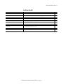
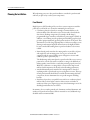
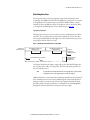
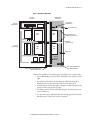
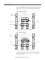
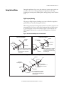
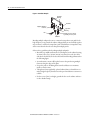
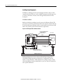
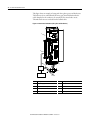
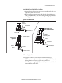
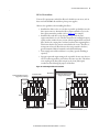
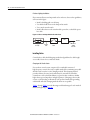
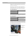
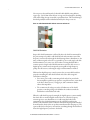
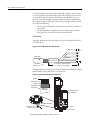
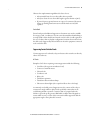
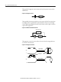
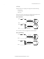
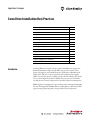
Application Technique
Servo Drive Installation Best Practices
Topic
Page
Introduction
1
Installation Checklist
3
Planning the Installation
4
Panel Material
4
Establishing Noise Zones
5
During the Installation
High Frequency Bonding
9
Installing System Components
12
Installing Cables
18
Suppressing Contact Switched Loads
25
Leakage Current Considerations
Isolation Transformers
Introduction
9
28
28
Component and Wiring Noise Zone Classifications
30
Additional Resources
32
Use this publication as a quick reference guide of installation best practices for
Rockwell Automation® single-axis and multi-axis servo drive systems. These
practices also apply to most variable frequency (VFD) drives, adjustable speed
(ASD) drives, and other control components with solid state power supplies
(SSPS). Use these best practice examples to help reduce the number of potential
noise or electromagnetic interference (EMI) sources in your system and make
sure that the noise sensitive components are not affected by the remaining noise.
EMI mitigation or management is a process that involves reducing and managing
the cause and magnitude of EMI, and then combining these reduced levels with
proper routing of generating and receiving conductors and components.
2 Servo Drive Installation Best Practices
While reading this reference guide, keep in mind the following key points that
tend to be misunderstood:
• EMI is present in all control systems and can affect expected signal
integrity, which can in turn cause circuits to energize or de-energize inputs
and loads, stopping production, and causing equipment failure.
• The frequency range of primary concern is 100 kHz to 10 MHz, which in
this document is referred to as high frequency or HF.
• The physics property skin-depth or skin-effect refers to the outer
circumferential depth of a conductor (from OD towards center) through
which AC current can flow. As the frequency increases, the skin depth
decreases. In addition, as the diameter of the conductor decreases or the
conductor length increases, the reflected impedance increases.
Consequently, it is important to avoid the use of long or high gauge (small
diameter) conductors for HF bonding purposes.
• Typical control wiring or conductors (green insulated ground wires)
reflect much higher impedance (resistance) at HF than is typically
expected, due to inductive reactance. The frequency effect is often
forgotten and the digital multi-meter resistance measurement of 0.1 or 1
ohm is based on the power frequency (50 and 60 Hz) and not at the HF
range (100 kHz to 10 MHz).
• Bonding conductors or components are not the same as ground
conductors or wires. The bond conductor’s purpose is to create an
equipotential level at HF for a control system and the ground conductor’s
purpose is to route unexpected, dangerous currents/voltages present on the
equipment chassis to earth ground. Due to the points mentioned above,
ground conductors provide a lower resistance to ground than body parts,
however, they do not typically make good low impedance paths to the
equipotential plane at HF. Failure to create low impedance paths from
component to component can result in an offset or potential difference
and voltage.
This document is not intended to replace any existing documentation including,
but not limited to, product user manuals, installation instructions, and the
System Design for Control of Electrical Noise Reference Manual, publication
GMC-RM001.
Rockwell Automation Publication MOTION-AT004A-EN-P - October 2011
Servo Drive Installation Best Practices 3
Installation Checklist
Section
Technique
Panel Material
Whenever possible, use galvanized or plated panels. For painted panels, remove paint from mating surfaces
Establishing Noise Zones
Noise zones established, clean/dirty components and cables segregated
High Frequency Bonding
Panels, ground buses, control components, and machine structure properly bonded
Grounding the Drive
Drive chassis and power rail (if applicable) properly grounded
Installing 24V Power Supplies
24V power supply properly grounded and decoupled at clean loads
Installing EMC Line Filters
EMC line filter installed as close to drive as possible
Installing Enclosure Lighting
Fluorescent lamps properly installed so as to suppress EMI
Installing Cables
Cables shielded where appropriate with 360° termination methods employed and grounded at both ends,
cable lengths minimized, and wire loops avoided
Suppressing Contact Switched Loads
Contact switched loads suppressed
Isolation Transformers
Isolation transformer used in place of EMC line filter (1)
(1) Use this technique only if designing to reduce leakage current, rather than to minimize noise. EMC line filter is required to meet CE approval.
Rockwell Automation Publication MOTION-AT004A-EN-P - October 2011
√
4 Servo Drive Installation Best Practices
Planning the Installation
When planning your servo drive panel installation, consider the panel material
and how you plan to lay out the system components.
Panel Material
High-frequency (HF) bonding of the servo drive system components with the
panel they are mounted on is essential to minimizing electrical noise:
• Conductive-plated steel panels are strongly recommended due to the
inherent ability of the material to resist corrosion and to bond with the
drive chassis, bonding components (for example, shield clamps),
programmable logic controllers, and solid state power supplies (SSPS). In
addition, a steel cabinet provides good magnetic shielding properties and
provides equipotential bond (ground) points anywhere on the panel. This
eliminates the need for long, high-impedance conductors routing to some
distant ground terminal. A plated cabinet frame is also highly desirable
because it makes HF bonding between panel and cabinet sections more
reliable.
• Painted metal panels must have the mating surfaces scoured free of paint
and roughed at each mounting point of every piece of metal-clad
equipment and the exposed surfaces protected against corrosion with
conductive paint or petroleum jelly.
The disadvantage with painted panels, apart from the labor cost to remove
paint and re-coat the areas with a conductive coating, is the difficulty of
making quality control checks to verify that paint was properly removed.
Without a conductive re-coating, future corrosion of the unprotected
mild steel will compromise the already reduced bonding performance.
• Anodized aluminum panels must have the mating surfaces cleaned of
anodizing and the exposed surfaces protected against corrosion. This type
of back panel material should also be avoided when mounting solid state
components, because aluminum does not provide magnetic shielding
benefits.
• Stainless steel panels are acceptable, but are inferior to conductive-plated
mild steel due to their higher resistance. Most versions or families of
stainless steel have poor magnetic properties, thus eliminating some of the
shielding benefits that sheet steel offers.
In summary, do not consider painted steel, aluminum, anodized aluminum, and
stainless steel panels and enclosures. If these materials are used, additional steps
should be taken to minimize EMI.
Rockwell Automation Publication MOTION-AT004A-EN-P - October 2011
Servo Drive Installation Best Practices 5
Establishing Noise Zones
You can greatly reduce noise by segregating components and wiring in zones
according to their EMI levels and noise susceptibility. A good practice to consider
is the application of colored wireways to provide the installer with a constant
reminder of where the different classes of conductors can be routed safely. Refer
to Component and Wiring Noise Zone Classifications on page 30.
Segregating Components
This figure shows how you can create three zones in a standard panel or cabinet
enclosure. The very-dirty items are placed in the right/front section. The dirty
items are placed behind them in the right/rear section and the least noisy (clean)
items are placed in the left/rear section.
Figure 1 - Relative Position of Noise Zones on the Panel
Main Panel or
Cabinet (top view)
Dirty Wireway and Component
Mounting Section
Clean Wireway and Component
Mounting Section
Left Side and Front Panels (if cabinet)
Right Side
Divider Panel
(multi-bay cabinets)
Very-dirty Cable Tray
and Component
Mounting Section
A side panel is fitted on the right to support the power cable shield clamps and
any very-dirty wires, cables, or components. This leaves the main panel free for
the clean and dirty zones.
TIP
It is preferable to mount the PLC and motion control equipment in a separate cabinet
away from the power control equipment (motor starters for example).
Additional isolation can be obtained by employing a simple slotted or perforated
sheet metal barrier between wire ducts. Maintain good contact with the plated
back panel surface to make sure the ‘L’ barrier has equipotential with the back
panel. Be careful to keep slots and holes to a minimum to avoid radiating EMI
through the material voids based on frequency and wave length.
Rockwell Automation Publication MOTION-AT004A-EN-P - October 2011
6 Servo Drive Installation Best Practices
Routing Cables
These figures provide examples of how to route clean, dirty, and very-dirty
wireways or cable trays within a panel. Refer to Component and Wiring Noise
Zone Classifications on page 30.
Figure 2 - Routing Clean and Dirty Cables
Main Panel (front view)
Power
Distribution
PSU
Dirty Zone
(black wireway)
PLC
PWM
Drive
Barrier
C
C
Sensitive
Equipment
PWM
Drive
A
Clean Zone
(gray wireway)
B
Clean
Relays
Dirty
Observe these guidelines when planning your panel layout for clean and dirty
cables:
• The plated steel barrier between clean and dirty wireways allows them to
run close together.
• If dirty power is required at A, then run it via wireway B using shielded
cable.
• The vertical wireway at C is not good practice as it encourages the creation
of loops (refer to Minimizing Loops on page 23).
• The use of different colored wireways (for example, gray for clean and
black for dirty) encourages good segregation.
When strict segregation is not practical, make sure that the cables cross at right
angles to minimize noise transfer.
Rockwell Automation Publication MOTION-AT004A-EN-P - October 2011
Servo Drive Installation Best Practices 7
Figure 3 - Routing Very Dirty Cables
Main Panel
(front view)
Right Side Panel
(inside view)
Segregation fro
Clean/Dirty Zone
Dirty Zone
(black wireway)
Zinc Plated Cable Tray
PWM
Drive
PWM
Drive
Drive Power Connections
(forming bridge to cable tray)
Very Dirty Zone
(white cable tray)
Clean Zone
(gray wireway)
PWM
Drive
PWM
Drive
Divider Panel
Clean and
Dirty Zone
Wireways
Divider Panel Bonded with Braided Strap
to Main Panel (three places)
Cable Tray Bonded with Braided
Strap to Main/Divider Panel
Observe these guidelines when planning your panel layout for very-dirty cables:
• Power cables bridge across to the drive terminals from the cable tray on the
right.
• The cable tray is bonded to the divider panel with braided strap. If no
divider panel is used, then bond the cable tray to the main panel.
• A divider panel is used on the right to segregate very-dirty wiring from the
clean zone of the next panel to the right.
• The divider panel is bonded with braided straps to the main panel at top,
center, and bottom.
• Use 25.4 mm (1.0 in.) wide braided strap for bonding (preferred method).
Braided strap 12.7 mm (0.5 in.) wide is acceptable.
Rockwell Automation Publication MOTION-AT004A-EN-P - October 2011
8 Servo Drive Installation Best Practices
You can convert wiring designated dirty or very-dirty to the next lower category
by using either shielded cable or conduit where required. These figures show how
this technique can be used to mix categories without breaking the segregation
rules.
Figure 4 - Very Dirty Cable in Clean Zone
Dirty Zone
EMC Filter to
Drive Cable
24V DC I/O
Cable
Very Dirty Zone
Dirty Zone
Motor Power Cable
Clean
Zone
Dirty Zone
Very Dirty Zone
A
Minimum 150 mm (6.0 in.) Segregation
Figure 5 - Clean Cable in Very Dirty Zone
Dirty Zone
Analog Device Cable
24V DC I/O
Cable
Clean Zone
Encoder Cable
Dirty Zone
Very Dirty
Zone
Dirty Zone
Clean Zone
A
Minimum 150 mm (6.0 in.) Segregation
The cable is locally shielded to cross another zone. Each shield is grounded at
each boundary and the cable is run close to the panel. The outer shield A is
thick-walled steel conduit.
Rockwell Automation Publication MOTION-AT004A-EN-P - October 2011
Servo Drive Installation Best Practices 9
During the installation of your servo drive and motor/actuator system, make sure
you observe these noise-reducing techniques for high-frequency bonding,
installing system components, installing cables, and suppressing contact switched
loads.
During the Installation
High Frequency Bonding
The purpose of high-frequency bonding is to present a defined low-impedance
path for HF noise currents returning to their source.
When using a painted panel, mating surfaces must be scoured free of paint at each
mounting point of every piece of metal-clad equipment. Exposed surfaces must
be protected against corrosion with conductive paint or petroleum jelly. The
following figure illustrates the recommended bonding practices for painted
panels.
Figure 6 - Recommended Bonding Practices for Painted Panels
Stud-mounting the Subpanel
to the Enclosure Back Wall
Stud-mounting a Ground Bus
or Chassis to the Subpanel
Subpanel
Back Wall of
Enclosure
Mounting Bracket or
Ground Bus
Subpanel
Welded Stud
Star Washer
Nut
Scrape Paint
Flat Washer
Welded Stud
Nut
Flat Washer
Use a wire brush to remove paint from
threads to maximize ground connection.
Use plated panels or scrape paint on
front of panel.
Star Washer
If the mounting bracket is coated with
a non-conductive material (anodized
or painted), scrape the material around
the mounting hole.
Bolt-mounting a Ground Bus or Chassis to the Back-panel
Subpanel
Bolt
Tapped Hole
Ground Bus or
Mounting Bracket
Nut
Star Washer
Scrape paint on both sides of
panel and use star washers.
Star Washer
Flat Washer
Nut
Flat Washer
Star Washer
If the mounting bracket is coated with
a non-conductive material (anodized
or painted), scrape the material around
the mounting hole.
Rockwell Automation Publication MOTION-AT004A-EN-P - October 2011
10 Servo Drive Installation Best Practices
Figure 7 - Ground Bus Example
Ground Bus
Mounting
Ground Bus
Equipment Grounding
Conductors
Tapped Hole
Ground Lug
Bolt
Grounding-electrode conductor
to grounding-electrode system.
Star Washer
Bonding multiple subpanels creates a common low impedance exit path for the
high frequency energy inside the cabinet. Subpanels that are not bonded together
may not share a common low impedance path. This difference in impedance may
affect networks and other devices that span multiple panels.
Observe these guidelines when bonding multiple subpanels:
• Bond the top, middle and bottom of each subpanel to the cabinet by using
25.4 mm (1.0 in.) by 6.35 mm (0.25 in.) wire braid. As a rule, the wider
and shorter the braid is, the better the bond. Panel bonding is illustrated in
the following figure.
• As an alternative, mount a filler plate between the panels using multiple
fasteners along the edges of the plate.
• Scrape the paint or anodizing from around each fastener to maximize
metal-to-metal contact.
• Though not always applicable, a plated cabinet frame is desirable since it
makes a high frequency bond between the panel and cabinet sections more
reliable.
• For doors 2 m (78 in.) in height, ground the door to the cabinet with two
or three braided straps.
Rockwell Automation Publication MOTION-AT004A-EN-P - October 2011
Servo Drive Installation Best Practices 11
Figure 8 - Panel Ground Plane Extended to Adjacent Panels
Adjacent panels
bonded to extend
the ground plane.
Cabinet Ground Plane
(component mounting panel)
Ground plane extended to side panel
by bonding to main panel.
Figure 9 - Bonded Ground Buses Connecting Multiple Subpanels
Bonded Ground
Bus
Ground Grid or Power
Distribution Ground
Always follow NEC and
applicable local codes.
Rockwell Automation Publication MOTION-AT004A-EN-P - October 2011
12 Servo Drive Installation Best Practices
Installing System Components
In addition to making good connections through each bolt or stud, use either
copper braid, 25.4 mm (1.0 in.) wide or 8 AWG minimum stranded copper wire,
to connect each chassis, enclosure, and central ground bus mounted on the
back-panel.
Drive/Motor Installations
Make sure that drive grounding is properly connected as illustrated below. The
ground wire return between the motor and the drive must be terminated directly
to the drive PE terminal. Shielded cable is recommended, but not always needed.
Refer to the product-specific documentation for requirements.
Figure 10 - Grounding the Drive and Motor/Actuator
Optional Enclosure
Connection to Drive Structure
or Optional Cabinet via
Conduit Connector
Motor Frame
Conduit
AC Drive
R
U
S
V
T
W
Motor
PE PE
Motor Frame
Ground
Panel Ground Bus
Ground Bus Connected
Directly to Drive PE Terminal
Building Ground Potential
Making an adjustment to the servo drive to bleed off static charges when
ungrounded or high-impedance grounded power configurations exist can
improve system performance. This usually involves a jumper setting or similar
action, depending on the drive family. Refer to your servo drive user manual for
drive-specific information.
Rockwell Automation Publication MOTION-AT004A-EN-P - October 2011
Servo Drive Installation Best Practices 13
Kinetix 300/350 Drive Installations
This figure shows an example of three-phase power wires for motors/actuators
that do not require brake wires. Thermal switch wires are included in the
feedback cable.
Figure 11 - Motor Power Terminations (three-phase wires only)
Motor Power Ground
Shield Clamp
25
(1.0)
34.0
(1.34)
12.7
(0.50)
Dimensions are in mm (in.).
50…75
(2…3)
50…75
(2…3)
If panel is painted, remove paint to
provide metal-to-metal contact.
Rockwell Automation Publication MOTION-AT004A-EN-P - October 2011
14 Servo Drive Installation Best Practices
This figure shows an example of wiring with three-phase power and brake wires.
The brake wires have a shield braid (shown as gray) that folds back under the
cable clamp before the conductors are attached to the motor brake circuit.
Thermal switch wires are included in the feedback cable.
Figure 12 - Motor Power Terminations (three-phase and brake wires)
6
5
7
3
2
8
4
1
To Motor
Item
Description
Item
Description
1
24V power supply
5
I/O (IOD) connector
2
Relay and diode assembly
6
2097-V3xPRx-xx Kinetix® 300/350 drive
3
Minimize unshielded wires in brake circuit
7
Motor power (MP) connector
4
MP-Series™ cable brake wires
8
Cable clamp
Rockwell Automation Publication MOTION-AT004A-EN-P - October 2011
Servo Drive Installation Best Practices 15
Kinetix 6000 and Kinetix 6200/6500 Drive Installations
• Attach the braided grounding strap from the grounding stud on the power
rail to the bonded cabinet ground.
• When installing mounting brackets with either the Kinetix 6000 power
rail (or the LIM module), attach the braided grounding strap as illustrated
in the figure below.
Figure 13 - Power Rail Grounding
Braided
Ground Strap
2094 Power Rail
PRS
PR
PR
Bonded Cabinet
Ground Bus
LIM
Ground Grid or Power
Distribution Ground
Line Interface Module on
Bulletin 2094 Mounting Brackets
Ground Stud
LIM
2094 Mounting Bracket
(2094-XNBRKT-1)
Ground Stud
PRS
PR/PRS
PR
PR
2094 Power Rail on
Bulletin 2094
Mounting Brackets
2094-XNBRKT-1
2094 Mounting Bracket
LIM
Bonded Cabinet
Ground Bus
PR
Braided
Ground Strap
PRS
LIM
Ground Stud
Braided
Ground Strap
Bonded Cabinet
Ground Bus
Ground Grid or Power
Distribution Ground
Ground Grid or Power
Distribution Ground
24V Power Supply Installations
Power supplies are inherently associated with two EMI related issues:
• The use of a common power supply (one power supply for all load types)
allows galvanic (conductive) coupling via the conductors.
• If solid state power supplies (SSPS) are used, they can generate EMI on the
input and output of the SSPS.
Rockwell Automation Publication MOTION-AT004A-EN-P - October 2011
16 Servo Drive Installation Best Practices
To avoid noise related problems caused by 24V DC power supplies, observe these
guidelines:
• Unless a floating supply is required, bond the common output terminal to
a ground terminal near the SSPS. Avoid the use of long conductor lengths,
> 150mm (5.9 in.) for this bond. This bond provides an equipotential
bond at high frequencies for all loads and normal machine wire appears as
high impedance at high frequencies. The longer the conductor, the higher
the impedance.
• Use a ground terminal installed on the DIN rail fastened to a zinc-plated
panel to make the ground connection. The use of clip-on or snap-on
grounding terminals should be avoided. Instead, use clamp-on style
grounding terminals for a mechanical connection and additional bonding
area.
• When a common supply is part of the system design, provide some
isolation, where needed, using low-pass DC filters. Refer to Chapter 5 of
the System Design for Control of Electrical Noise Reference Manual,
publication GMC-RM001, for more information.
An option for suppressing the related noise is to decouple the +24V DC line to
the same ground terminal with a 1 μF, 50V ceramic capacitor to achieve the clean
category.
Single-phase Power Supply Installations
To avoid noise related problems caused by single-phase power supplies, observe
these guidelines:
• Treat single phase wiring as dirty.
• Include line filters for loads that create noise, such as PWM devices with
DC switch-mode power supplies and fluorescent cabinet lights.
• Include line filters for potentially sensitive loads, such as PLC logic power.
• Mount the line filter as close to the load as possible.
Rockwell Automation Publication MOTION-AT004A-EN-P - October 2011
Servo Drive Installation Best Practices 17
EMC Line Filter Installations
To meet CE requirements, include line filters for loads that create noise, such as
drives and other PWM loads with three-phase power supplies.
Observe these guidelines when installing line filters:
• Install the line filter as close to each drive as possible, preferably next to the
drive input connector. Position the filter output terminals as close to the
drive input terminals as possible (refer to Figure 14 for example).
• Install the filter and drive on the same panel to provide the same
equipotential surface to each. The filter chassis has internal high-frequency
capacitors that conduct the stray current (which originated in the attached
drive) back to the output phase conductors and into the originating drive.
This means that the stray currents return back to the source. Therefore, it
is important to have the filter chassis at the same potential as the drive,
ground terminals, DIN rail terminals, and cable shield clamps.
• Treat wiring between filter and drive as very-dirty (provide shielding as
required).
• Segregate input and output wiring as far as possible. Do not route the two
sets of conductors parallel to each other in the same wire duct. This allows
cross coupling of the dirty (filter output) to the clean (filter input)
conductors, thus defeating the purpose of the filter.
Figure 14 - Positioning Line Filter and Servo Drive
Dirty Wireway
Very Dirty Filter/Drive Connections
Segregated (not in wireway)
Very Dirty Filter/Drive Connections
Segregated (not in wireway)
Motor Power Cables
Very Dirty
Zone
Motor Power Cables
Very Dirty
Zone
VAC Load
AC Line Filter
VAC Load
VAC Line
Dirty Wireway
VAC Line
Kinetix 6000 Drive System
(line filter mounted behind drive system)
Rockwell Automation Publication MOTION-AT004A-EN-P - October 2011
Kinetix 6000 Drive System
(line filter mounted left of drive system)
18 Servo Drive Installation Best Practices
Enclosure Lighting Installations
If you must use fluorescent lamps inside of an enclosure, observe these guidelines,
as shown in the figure:
• Install a shielding grid over the lamp.
• Use shielded cable between the lamp and its switch.
• Use a metal-encased switch.
• Install a filter between the switch and the power line, or shield the power
line cable.
Figure 15 - Fluorescent Lamps Wired Inside an Enclosure
Filter
Shielding-grid
Over Lamp
Shielded
Cable
Metal Encased
Switch
AC Power
Line Filter or
Shielded
Power Line
Installing Cables
Consider these cable shield clamping methods and guidelines for cable length,
excess cable, ferrite sleeves, and ferrite beads.
Clamping at the Circular Section
For a modern control system, comprised of a considerable amount of
high-frequency currents, the only acceptable method for terminating most cable
shields is with a circular or 360° clamping method. This clamping method
provides a balanced contact and conductivity for current flow around the
circumference of the shield. In addition, a typical circular conductor exhibits
higher than expected impedance at high frequencies. Clamping at the circular
section or 360° bonding, as illustrated, is the preferred method for grounding
cable shields. All of the clamping methods shown are acceptable.
Table 1 through Table 4 provide advantages and disadvantages for each method
illustrated beginning on page 19.
Rockwell Automation Publication MOTION-AT004A-EN-P - October 2011
Servo Drive Installation Best Practices 19
Figure 16 - Cable Clamping Methods
A
A
Table 1 - Spring Clamp (method A)
Advantages
Disadvantages
Very effective method
Easy to install - snap or screw clamp onto DIN rail and insert cable section
Cost
Plated material - conductivity and oxidation benefits from dissimilar
metals
Limited strain relief capabilities
Sized to accommodate wide range of cable diameters
Provides good 360° bonding to exposed braided shield area
Figure 17 - Cable Clamping Methods (continued)
B
C
D
Table 2 - Heavy Duty Commercial Cable Clamp (method B)
Advantages
Disadvantages
Very effective method
Cost
Each size covers a wide range of diameters
Limited strain relief
No additional drilling or tapping required
Poor availability in some areas
Rockwell Automation Publication MOTION-AT004A-EN-P - October 2011
20 Servo Drive Installation Best Practices
Strapping your cable to a DIN rail (the cable labeled C) is crude, but effective.
The DIN rail is raised off the panel slightly by using conductive washers to allow
metal cable ties to pass underneath.
If spacing is desired, care should be taken to use large outer-diameter plated
washers for the gap to maximize contact area. Metal ties should be thin enough to
avoid the spacing washers. The use of non-conductive ties will not provide
adequate, balanced conductivity around the circumference of the cable shield.
Table 3 - Strapping to DIN Rail (method C)
Advantages
Disadvantages
Very effective method
Each size covers a wide range of diameters
Moderate strain relief
Appearance
Low cost
Plain copper saddle clamps (the cable labeled D) are sold for plumbing purposes,
but are very effective and available in a range of sizes.
Table 4 - Saddle Clamp (method D)
Advantages
Very effective method
Available in a wide range of sizes
Excellent strain relief
Low cost
Disadvantages
Requires two drilled and tapped holes per cable
Each size will accommodate a limited range of diameters
Additionally, you can install and mount flat copper or galvanized plated tabs to
the plated back panel. Use these tabs with metal cable ties or small hose clamps to
form a simple 360° cable shield termination with good strain relief. This method
is easy to install and made from ordinary shop materials.
Figure 18 - Cable Clamping Methods (plated tabs and hose clamp)
Steel Tab with Turned-up End to
Hold Clamp in Place
Exposed Shield Braid Covered
with Copper Tape
Basic Hose Clamp
Rockwell Automation Publication MOTION-AT004A-EN-P - October 2011
Servo Drive Installation Best Practices 21
You can protect the small strands of a braided cable shield by using adhesive
copper tape. Use foil that offers the best coverage and electromagnetic shielding
of the cables. Wrap the tape around the exposed braid area. This avoids having to
bend and possibly break the individual strands by the clamp or wire tie.
Figure 19 - Cable Clamping Methods (adhesive copper tape and wire tie)
Cable Shield Terminations
Proper cable shield termination is affected by where the shield is terminated. In
the past, attempts to bond the cable shield at both ends sometimes caused low
frequency currents to flow through the shield causing a hum or disturbance to the
inner conductor signal, referred to as a ground loop. As a result, single-end cable
shield termination or in some cases, the avoidance of using shielded cable is
common practice. Single-ended shield termination causes the cable to act as a
high-frequency antenna and consequently is susceptible to high-frequency
pickup. For this reason, avoid using the single-ended termination method.
With modern high-frequency control systems, there are noticeable benefits to
properly terminating the cable shield at both ends of the cable using 360°
termination techniques:
• For a motor power cable, terminating at both ends often provides the
lowest impedance path for stray capacitive-coupled currents to return back
to the drive chassis (source). Using proper 360° terminations further
reduces this impedance.
• The common-mode voltage across the self-inductance of the shield
generates a canceling voltage to the EMI in the conductors inside the
shield when it is bonded at both ends.
When the cable shield is properly managed, the high-frequency currents usually
have little effect on modern digital circuits. However, if the low-frequency
currents appear to cause disturbances on a cable using dual-ended 360°
terminations, then a hybrid termination can be achieved by replacing the
machine-end termination with a conductive band and 1.0 μF capacitor installed
from the band to chassis (there are products manufactured for this purpose). The
capacitor blocks low-frequency currents from circulating through the shield and
shorts the high-frequency currents to the shield.
Rockwell Automation Publication MOTION-AT004A-EN-P - October 2011
22 Servo Drive Installation Best Practices
A common mistake when terminating a cable shield is using the drain conductor
to create a pigtail by twisting the braid together and inserting a portion of it into
a convenient, inexpensive terminal. This technique should not be used, as it
generates a large loss through potential attenuation or reduction in EMI on the
inner signal conductors of the cable. The benefits of the cable shield are reduced
as a result of the following:
• The non-uniform distribution of shield current around the circumference
of the shield
• The added impedance at high frequencies created by using a conductor
effect and the loss of conductive contact at the bond point
Shielding Cables
This figure illustrates how to properly prepare the power cable shield braid for a
360° cable clamp.
Figure 20 - Power Cable Shield and Lead Preparation
Strip Length
U
V
Outer Insulation
W
Motor Power Cable
Exposed Braid
25.4 mm (1.0 in.)
As required to have ground clamp within
50…75 mm (2…3 in.) of the drive.
This figure illustrates how to properly clamp the flying-lead feedback cable shield
braid and make wiring connections in a connector kit.
Figure 21 - Feedback Cable Shield and Lead Preparation
Bare Wires
Wire Insulation
Foil Shield
Outer Insulation
Bulletin 2090
Feedback Cable
Clamp
Exposed Braid Under Clamp
0 15 14 13 12 11 10 9 8 7 6 5 4 3 2 1
Braided Shield
Turn clamp over to hold
small wires secure.
Low Profile Connector Kit
(2090-K2CK-D15M)
Tie Wrap
Bulletin 2090 Feedback Cable
Rockwell Automation Publication MOTION-AT004A-EN-P - October 2011
Servo Drive Installation Best Practices 23
Cable Lengths
Although motor power and feedback cables are available in standard lengths up
to 90 m (295.3 ft), the drive/motor/feedback combination may limit the
maximum feedback cable length. Combined motor power cable length for all
axes on the same DC bus is also subject to drive-specific limitations. Refer to your
servo drive user manual for more information.
Minimizing Loops
Wires that form a loop make an efficient antenna. Run feed and return wires
together rather than allowing a loop to form. Twisting the pair further reduces
the antennae effects and can significantly reduce EMI.
Figure 22 - Avoiding Loops in Wiring Designs
Switch
Not Recommended
Switch
Good Solution
TIP
Switch
Better Solution
This applies to victim wiring too. Antennae work equally well in receive and transmit
modes.
The twisting of the signal pair reduces the magnetic field pickup area and helps to
make sure that both conductors in the pair couple have the same level of EMI. As
a result, the EMI is rejected by the differential op-amp receiver.
Rockwell Automation Publication MOTION-AT004A-EN-P - October 2011
24 Servo Drive Installation Best Practices
Excess Cable
Observe these guidelines when handling excess cable:
• Do not coil excess cable of different types (for example, motor power and
feedback) together. An efficient transformer is formed at HF.
• Cable lengths should ideally be trimmed to fit the application.
• If excess cable cannot be trimmed, it should be laid in an 'S' or figure eight
pattern (refer to the figure below).
Figure 23 - Excess Cable Treatment
Preferred Methods
Poor Method
Ferrite Sleeves
Shielded data cables grounded at both ends (important at high frequencies) may
carry noise current due to voltage differences between the two ends. Because the
shields have a low impedance, currents may be quite high even though voltage is
low. By installing ferrite sleeves, the common-mode impedance of the cable is
greatly increased at high frequencies, thus blocking the noise currents without
affecting the signal currents. In this figure, capacitor grounding is very effective
and avoids no-grounding rules, but can be awkward to implement.
Figure 24 - Ferrite Sleeves Increase Common Mode Impedance
Ferrite sleeve greatly
increases impedance at RF.
Signal
Source
Optional Capacitor
V
Panel A
Differential Noise Voltage
Rockwell Automation Publication MOTION-AT004A-EN-P - October 2011
Panel B
Servo Drive Installation Best Practices 25
Observe these implementation guidelines for ferrite sleeves:
• Always install ferrite sleeves to data cables where specified.
• Always use ferrite sleeves when cable length is greater than 10 m (30 ft).
• If power frequency ground currents are expected, or measured by current
clamp, one shield/ground connection could be made via a 1uF, 50V
capacitor.
Ferrite Beads
Ferrite beads provide additional suppression of transient noise and are available
for category-2 and -3 conductors. You can secure them with heat-shrink tubing or
tie-wraps. With a ferrite bead located near the end of a cable (or cable segment in
the case of a daisy-chain or dropline configuration) transient noise induced onto
the cable can be suppressed by the bead before it enters the equipment connected
to the end of the cable.
Suppressing Contact Switched Loads
Contact suppressors for solenoids, relays, and various other switches can directly
reduce electrical noise.
AC Circuits
Examples of AC devices requiring contact suppression include the following:
• Line filters (often present an inductive load)
• Contactor controlled motors
• Solenoid coils
• Conductor coils
• Relay coils
• Transformer primaries
• Transformer driven indicator lamps
• Fluorescent cabinet lights (also require line filters close to the lamp)
A commonly overlooked point of suppression are the contacts of the relays or
contactors for single and three-phase loads, specifically contacts that can be
cycled during machine operation. Contactors that are energized when the
machine is powered up may generate EMI which could be missed by signals or
circuits which are not yet active. Other contacts should be suppressed with the
appropriate single or three-phase RC network.
Rockwell Automation Publication MOTION-AT004A-EN-P - October 2011
26 Servo Drive Installation Best Practices
This typical RC suppressor circuit consists of a 0.1 μF capacitor in series with a
100 Ω resistor.
Figure 25 - RC Suppressor Circuit
0.1 μF
100 Ω
This typical RC plus transient absorber circuit consists of the RC network shown
in the figure above in parallel with a transient absorber. These are used in high
current, high energy applications such as motor starters. A three-phase contactor
requires three suppressors.
Figure 26 - RC Plus Transient Absorber Circuit
Transient Absorber
0.1 μF
100 Ω
This suppressor across the contact reduces the noise from the wiring inductance
as well as the coil inductance.
Figure 27 - RC Suppressor in Circuit
L
Good Solution
Line
N
Load
RC Suppressor
L
Better Solution
Line
N
Rockwell Automation Publication MOTION-AT004A-EN-P - October 2011
Load
Servo Drive Installation Best Practices 27
24V DC Circuits
Examples of DC devices requiring contact suppression include the following:
• Solenoid coils
• Contactor coils
• Relay coils
The first choice for DC circuit suppression is a flywheel diode, but this increases
the release time that may not be acceptable in all applications.
Figure 28 - Flywheel Diode
+24V DC
Good Solution
Flywheel Diode
Common
+24V DC
Better Solution
Common
Flywheel Diode
The second choice for DC circuit suppression is a transient absorber.
Figure 29 - Transient Absorber
+24V DC
Good Solution
Common
Transient Absorber
+24V DC
Better Solution
Common
Transient Absorber
Rockwell Automation Publication MOTION-AT004A-EN-P - October 2011
28 Servo Drive Installation Best Practices
Leakage Current Considerations
Leakage current is inevitable in servo drive systems due to the capacitive
components within the drives. Another source for leakage current is the cabling
in the system, which induces capacitance in the system. As cable lengths increase
so does leakage current. In addition, the leakage current increases with
unbalanced loads from the mains phases and when the number of drives increases
in a system. Finally, line filters drastically increase the leakage current in the
system. This presents a particular challenge in designing a system to reduce noise
and leakage current.
If a filter must be used for EMC purposes, but European Conformity (CE) is not
required, consider applying a low leakage current filter to reduce overall leakage
current.
If using an Earth Leakage Circuit Breaker (ELCB), consider reducing the
sensitivity to minimize nuisance trips. In some cases a harmonic filter (to filter
noise) in conjunction with a circuit breaker set at 60 Hz (to protect personnel)
can replace the ELCB.
IMPORTANT
Reduce cable lengths as much as possible to minimize capacitive loading along cables.
Isolation Transformers
If European Conformity (CE) is not a requirement, consider installing a system
isolation transformer rather than an EMC line filter to isolate noise within the
system. Transformers must be sized at double the sum of the output power of
each axis.
An isolation transformer is frequently assumed to give good noise isolation. In
fact, this applies only if the transformer is equipped with one or more
electrostatic (ES) shields, as illustrated in the figure below.
Figure 30 - Electrostatically Shielded Transformer
Primary
Secondary
Frame Bonded to
Ground Plane
Ground Plane
Shields Bonded to
Ground Plane
Rockwell Automation Publication MOTION-AT004A-EN-P - October 2011
Servo Drive Installation Best Practices 29
This technique is very effective, though EMC filters are required to meet
European regulation standards. Observe these guidelines when installing
transformers:
• Install the transformer to the same panel as the rest of your system (or
HF bond from panel-to-panel).
• Treat wiring between transformer and drive as very-dirty when no EMC
filter is present (provide shielding as required).
• Bond shield, if used, with braid directly to the panel. The transformer
mounting bolts are useful for this.
• Segregate input and output wiring as far as possible.
When using an isolation transformer, attach a chassis ground wire to the neutral
connection. This grounded neutral connection does the following:
• Prevents the system from floating and thereby avoids any high voltages that
might otherwise occur, for example, due to static electricity.
• Provides a solid earth path for fault conditions.
ATTENTION: If the supply transformer is an auto transformer (not recommended), a
chassis earth ground should not be added. A chassis earth ground should already be
included elsewhere in the system and adding another would create a short.
Rockwell Automation Publication MOTION-AT004A-EN-P - October 2011
30 Servo Drive Installation Best Practices
Component and Wiring Noise
Zone Classifications
These tables indicate the zoning requirements of cables connecting to the drive
components.
Table 5 - Component Noise Zone Categories
Zone (1)
Component Noise Zone Description
Method
Very Dirty
Dirty
Clean
PWM drives/amplifiers (4)
X
X
X
Dynamic braking components
X
External dump resistor (shielded)
EMC line filter
X
Switch-mode DC power supply
X
X
Contactors
X
MCB
X
Switched 24V DC loads (5)
(for example, E-stop/Piltz circuit, solenoids, relays)
X
X
X
Encoder buffer board
X
PLC
X
Registration 24V DC power supply filter
X
X
X
Linear DC power supply
X
Other 24V DC non-switched loads
X
Data/communication devices
X
Analog devices
X
(1)
(2)
(3)
(4)
(5)
Shielded (3)
Cable
X
X
X
Dirty to clean filter
Ferrite (2)
Sleeve
X
Dump resistor module (metal-clad)
Ultrasonic transducer
Suppress
An X in multiple zones indicates that the component straddles the two zones. Under these circumstances it is important to position the component in the correct orientation.
An X in this column indicates a ferrite sleeve fitted to the wire is recommended.
An X in this column indicates a shielded cable is recommended.
The connector/terminal block locations on the drive will normally dictate the zone geometry since it normally has connections in all categories. Design zones around the drives.
All inductive switched loads must be suppressed.
Rockwell Automation Publication MOTION-AT004A-EN-P - October 2011
Servo Drive Installation Best Practices 31
Table 6 - Wiring Noise Zone Categories
Wiring Noise Zone Description
Zone
Very Dirty
Dirty
Method
Clean
Suppress
Ferrite (1)
Sleeve
Shielded (2)
Cable
Three-phase between sine filter and drive (shielded)
X
X
Extended DC bus (shielded)
X
X
PWM drive/inverter to motor power (shielded)
X
X
PWM drive/inverter to sine wave filter
X
Sine wave filter to motor
X
CM choke to motor power (shielded)
X
X
Line terminator to motor power (shielded)
X
X
External dump shunt resistor (shielded)
X
X
Contactor to AC motor (shielded)
X
X
Three-phase power supply
X
Single -phase power supply
X
24V hydraulic/pneumatic to solenoids
X
Motor feedback resolver (shielded)
X
PLC digital I/O
X
Dedicated drive inputs (except registration)
X
Limit switches
X
Push buttons
X
Proximity switches (except registration)
X
Photoelectric cell
X
24V DC relay
X
Transformer indicator lamp
X
X
Data/communication (shielded)
X
Encoder/resolver (shielded)
X
X
Logic circuit power (shielded)
X
X
High-speed registration inputs (shielded)
X
X
PLC analog I/O
X
X
PLC high-speed counter input
X
X
(1) An X in this column indicates a ferrite sleeve fitted to the wire is recommended.
(2) An X in this column indicates a shielded cable is recommended.
Rockwell Automation Publication MOTION-AT004A-EN-P - October 2011
X
X
Additional Resources
These documents contain additional information concerning related products
from Rockwell Automation.
Resource
Description
System Design for Control of Electrical Noise Reference Manual, publication GMC-RM001
EMC Noise Management DVD, publication GMC-SP004
Information, examples, and techniques designed to minimize system failures caused
by electrical noise.
Wiring and Grounding Guidelines for Pulse Width Modulated (PWM) AC Drives,
publication DRIVES-IN001
Provides basic information needed to properly wire and ground pulse width
modulated (PWM) AC drives.
Industrial Automation Wiring and Grounding Guidelines, publication 1770-4.1
Provides general guidelines for installing an Allen-Bradley® industrial automation
system that may include programmable controllers, industrial computers,
operator-interface terminals, display devices, and communication networks.
You can view or download publications at
http://www.rockwellautomation.com/literature. To order paper copies of
technical documentation, contact your local Allen-Bradley distributor or
Rockwell Automation sales representative.
Allen-Bradley, Kinetix, MP-Series, Rockwell Software, and Rockwell Automation are trademarks of Rockwell Automation, Inc.
Trademarks not belonging to Rockwell Automation are property of their respective companies.
Publication MOTION-AT004A-EN-P - October 2011
Copyright © 2011 Rockwell Automation, Inc. All rights reserved. Printed in the U.S.A.