1
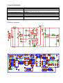
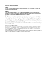
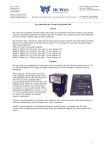
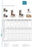
de Wijs.
Vleugelboot 68,
3991 CL Houten
the Netherlands
Tel. +31 (0)30 - 6364928
Fax. +31 (0)30 - 6361723
e-mail: [email protected]
Website: www.dewijs-3d.com
Design and production of stereoscopic instruments.
Account number: 129079073
Swiftcode/BIC: RABONL2U
IBAN: NL78RABO0129079073
Bank: Rabobank Houten
Street: Hofspoor 1
Postal code: 3994VZ
City: Houten
Tax number: NL 1899.16.084 B01
K.v.K. Reg. Nº 23071201 Utrecht
User manual
Viewer illumination 05-13C-LA
modification 2012
For the Combi 3D slide viewer
The content of this document is subject of change without notice. November 2012
General:
This viewer illumination is designed to couple with the Combi 3D viewer models of 1994,
2000 and 2003. Model 1997 is to narrow. In 2012 the light source and the electronics have
been modified. The light source is now based on LED back light and operates on a lead
acid gel battery as well as a mains adapter. The 5000 Kelvin color white illumination will
present your images with the original colors even when the lamp is dimmed.
Mount the viewer illumination on the Combi viewer.
•
•
•
•
•
•
Put the illumination upside down on the
table.
At the front – underside you see a small
metal strip as shown in the right image.
It can be pushed away inside the
housing.
Take a pen and push with the tip the
metal strip aside at the underside in the
hole.
Now take the viewer and let it shift in
the grooves at both sides of the
illumination housing
If you mount it for the first time, you
have to adjust the steel clamps at the left and right side to fit properly with your model
of Combi viewer.
When the viewer fits, release the metal strip as soon as the viewer is totally dropped
in its slot.
Normal use of the viewer illumination.
Pushing the red button turns on the light. Releasing it turns it off. When the viewer
illumination is connected to the external adapter, the battery is charged anytime.
With the connected adapter and the black slide switch is moved, the lamp turns on and
stays on. This only applies when the external adapter is used.
Brightness can be adjusted by turning the knob at the rear.
Battery
In mobile use, the viewer illumination runs on a single lead acid battery of 6 Volts 1.3Ah.
During tests it appeared that the illumination runs for about 6 hours. The LED back light
uses about 160 mA. at 5 Volts dc. As soon as the external adapter is connected, the battery
is charged until a certain voltage level is reached, then it stops. A small red LED at the
power plug indicates charging. This is a low charging current so from empty to full takes
about 1 day.
Exchanging the battery:
After a significant time it appears that the battery does not have enough power for good
operation even when charged. It has to be replaced.
-
-
At the underside, remove the four M3 bolts and remove the cover
Now carefully remove the 2 small white connectors at the rear of the housing (with
red and black leads). Pull them straight out of the socket, don’t tilt them, it might
break the socket.
Take the battery unit at the sides and pull it out of the housing. The LED panel comes
free as well.
Now unplug the connector on the battery and replace it on the new battery.
Warning! Pay attention to the polarity of the battery; red lead to +, black to Warning! Take notice of the position of the small white connectors at the rear when
you replace them; replace the battery plug to the correct socket.
Adding color filters to the back light
The 5000K color temperature of the LED backlight (pure white) is considered as base to
change to light color temperatures of your choice.
To reduce the color temperature to about 4600K, which is a warmer tint, can be achieved by
for example Lee filter type 443.
This filter is already inserted between the front colorless plexi-glass plate and the LED
panel.
To replace the filter, you need to take the battery out first. See the previous chapter for
directions how to do this. Then the LED panel and the plexi-glass plate are coming out as
well. Be careful with the leads to the LED panel, they are vulnerable. Do not bend the
contact points of the LED panel, they break otherwise.
Technical information.
Type of illumination
External and internal Voltage
Power consumption.
Charge current of the batteries
Illuminated area
Width of the coupled viewer
Expected lifespan of the lamp.
With full batteries expected usage
time.
Electronic schematics.
LED back light 5000K 130x60 mm. 5Vdc 160 mA.
12 Vac 500mA. external and 9 Vdc stabilized internal.
160 mA for the lamp, in total 3.5 Watts (with charging)
plug 5,5 mm. outer 2,1 mm. inner.
< 125mA
109 x 47.5 mm.
120 mm. x 55 mm. Height
30.000 hours, given by the lamp factory.
± 6 hours, depending on the type of battery and condition.
Electronic design explanation.
Power:
12 Volts ac should be connected to the light attachment. The circuit holds a rectifier and
voltage stabilizer to 9 Volts dc.
Battery:
The 6 Volts lead acid battery 1.3 Ah. Is able to provide about 6 hours of light when full
charged. The choice for this battery is because it does not need a difficult charging circuit,
the battery is one unit with solid connections, easy to replace.
Charging:
The charging curve of the lead acid battery is a little slope climbing up to about 7.45 Volts.
In the circuit a operational amplifier is checking the battery voltage and a pre-set cut-off
voltage (P2). Around this pre-set voltage, a hysteresis of about 0,5 Volts is added. So this
pre-set voltage is set to 7 Volts. The charging starts at 6.75 Volts and stops at 7.25 Volts.
You can check the pre-set voltage at TP1. The hysteresis compensated battery voltage can
be checked on TP2. Both with respect to ground.
The charging current is limited by LM317 and R9 to about 125mA. Even when the battery is
short circuited / defect.
Power for the LED backlight:
The relais in the circuit play’s an active role for the change of battery powered or adapter
powered use. It prohibits the battery to be discharged by the charging circuit when not in
use and prohibits the battery to be discharged when the slide switch is set to continuous
light in mobile use and not turned off.
The feature of dimming the light is realized around opamp U3. A zener diode D7 provides a
stable 5.1 volts reference for the driver circuit of the LED panel.