1
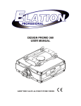
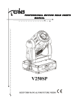
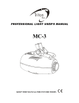
USER MANUAL
EXPLORER
Caution!
Be careful with your operations. With a dangerous voltage you can suffer a dangerous
electric shock when touching the wires!
Keep this device away from rain and moisture!
Make sure it is grounded when using it!
Unplug mains lead before opening the housing!
For your own safety, please read this user manual carefully before you initial start-up.
Every person involved with the installation, operation and maintenance of this device has
to
- be qualified
- follow the instructions of this manual
Introduction
Thank you for having chosen Explorer moving head wash light. You will see you acquired
a powerful and versatile device. Unpack your item. Before you initial start-up, please make
sure that there is no damage caused by transportation. Should there be any, consult your
dealer and do not use the device.
Safety instructions
This device has left our premises in absolutely perfect condition. In order to maintain this
condition and to ensure a safe operation, it is absolutely necessary for the user to follow
the safety instructions and warning notes written in this user manual. Always disconnect
from the mains, when the device is not in use or before cleaning it. Keep away children
and amateurs from the device! There are no serviceable parts inside the device.
Maintenance and service
operations are only to be carried out by authorized dealers.
Features
36 * 10W high power RGBW 4-in-1 LED
Extremely Long Life:50,000 Hr and low power consumption
DMX channel:7/13 channels
Zoom function
Beam angle:15-60°
Pan/tilt movement: 8 bit and 16 bit resolution
Three operation modes: DMX 512 protocol, stand alone, master/slave
For smooth and precise resolution
Pan: 540 optional, Tilt: 270 movement
High speed of pan/tilt movement, speed of pan/tilt movement is adjustable
1
Scan position memory, auto reposition after unexpected movement
Strobe effect with 18 flashes per second and pulse effect
General dimming and blackout for all four colors
Excellent color mixing and rainbow effect
Friendly blue LCD display
Preset program: 7 built in programs can be called up via DMX controller
Dimension
2
Installation
On the rear panel of the item you can find an 3pin XLR-jack (DMX Out) and an 3pin
XLR-plug (DMX In), which can be used for connecting several devices. Choose the device
which is to control the effects. Connect the DMX OUT-jack with the DMX IN-plug of the
next device.
DMX-512 connection / connection between fixtures
Occupation of the XLR-connection:
If you are using controllers with this occupation, you can connect the DMX-output of the
controller directly with the DMX-input of the first fixture in the DMX-chain. If you wish to
connect DMX-controllers with other XLR-outputs, you need to use adapter-cables.
Building a serial DMX-chain:
Connect the DMX-output of the first fixture in the DMX-chain with the DMX-input of the
next fixture. Always connect one output with the input of the next fixture until all fixtures
are connected.
DMX-512 connection with DMX terminator
For installations where the DMX cable has to run a long distance or is in an electrically
noisy environment, such as in a discotheque, it is recommended to use a DMX terminator.
This helps in preventing corruption of the digital control signal by electrical noise. The
DMX terminator is simply an XLR plug with a 120 resistor connected between pins 2 and
3,which is then plugged into the output XLR socket of the last fixture in the chain. Please
see illustrations below.
3
Caution: At the last fixture, the DMX-cable has to be terminated with a terminator. Solder
a 120 resistor between Signal (–) and Signal (+) into a 3-pin XLR-plug and plug it in the
DMX-output of the last fixture.
Connection with the mains
Connect the device to the mains with the enclosed power supply cable.
Overview
(1) Lens
(2) Yoke
(3) Base
(4) Carrying handle
(9) Enter-button
(10) Control Board
(11) Housing
(12) 3-PIN DMX output socket
4
(5) LCD-Display
(6) Mode/esc-button
(7) Up-button
(8) Down-button
(13) 3-PIN DMX input socket
(14) Power switch
(15) Fuse
(16)Power supply
Control menu map
5
6
Operation
Projector DMX starting address selection
All fixtures should be given a DMX starting address when using a DMX signal,so that the
correct fixture responds to the correct control signals. This digital starting address is the
channel number from which the fixture starts to listen to the digital control information sent
out from the DMX controller. The allocation of this starting address is achieved by setting
the correct number on the display located on the base of the device.
You can set the same starting address for all fixtures or a group of fixtures, or make
different address for each fixture individually.
7
If you set the same address, all the units will start to listen to the same control signal from
the same channel number. In other words, changing the settings of one channel will affect
all the fixtures simultaneously.
If you set a different address, each unit will start to listen to the channel number you have
set,based on the quantity of control channels of the unit. That means changing the
settings of one channel will affect only the selected fixture.
In the case of the moving head, which is 13 channels fixture when you select the standard
channel mode, you should set the starting address of the first unit to 1, the second unit to
17(16+1), the third unit to 33(16+17), and so on.
Control Board
The Control Board offers several features: you can simply set the starting address, switch
on and off the lamp, run the pre-programmed program or make a reset.
The main menu is accessed by pressing the Mode-button until the display starts flashing.
Browse through the menu by pressing the Up-button or Down-button. Press the
Enter-button in order to select the desired menu. You can change the selection by
pressing the Up-button or Down-button. Confirm every selection by pressing the
Enter-button.You can leave every mode by pressing the Mode-button.The functions
provided are described in the following sections.
DMX Protocol
Mode/Channel
Function
Value
Type of control
CH1
General dimming
0-255
proportional
CH2
Strobe
0-255
proportional
CH1
CH3
Red
0-255
proportional
CH2
CH4
Green
0-255
proportional
CH3
CH5
Blue
0-255
proportional
CH4
CH6
White
0-255
proportional
CH7
CT
0-8
9-255
OFF
3200K-6500K
CH5
CH8
X-movement
0-255
0-540°
CH6
CH9
Y-movement
0-255
0-270°
CH10
X/Y-movement speed
0-255
Inversely proportional
CH11
CMY color mixing
0-255
proportional
OFF
Reset(stop 5S)
built-in program
proportional
1/7
CH7
2/13
CH12
CMY
0-95
96-127
128-255
CH13
Zoom
0-255
Choose Channel mode
Turn on the fixture,you will see the follow:
MOVING
D:001
LED
no
MENU
MAIN
Address
MENU
UP
DOWN
MAIN
MENU
Change-CH
Then,press"ENTER" to enter the modes of choosing DMX channels.
Mode 1:
8
Channel
Function
CH1
Red
CH2
Green
CH3
Blue
CH4
White
CH5
X-movement
CH6
Y-movement
CH7
Zoom
Channel
Functions
CH1
General dimming
CH2
Strobe
CH3
Red
CH4
Green
CH5
Blue
CH6
White
CH7
CT
CH8
X-movement
Mode 2:
9
CH9
Y-movement
CH10
X/Y-movement speed
CH11
CMY
CH12
CMY
CH13
Zoom
Set DMX address
Display the DMX 512 value of each channel.With this function you can display the DMX
512 value of each channel. The display automatically shows the channel with a value
changing.
Synchronization & master /slave mode
Take some items and connect them by DMX cables, disconnect the items from DMX
controller, the items will wok synchronously, one as master, the others as slave.
Auto Program
With this function, you can run the internal program. You can select the desired program
under.You can set the number of steps under .You can edit the individual scenes
under .With this function, you can run the individual scenes either automatically, i.e. with
the adjusted Step-Time.
Error message
When you turn on the fixture, it will make a reset first. The display may show XXer while
there are problems with one or more channels. XX stands for channel1, 2, 3,etc who has
the testing sensor for positioning.For example,when the display shows Red Er , it means
there is some error in channel 1,If there are some errors on channel 1, channel 2, channel
5 at the same time, you may see the error message Red Color Er , Green Er ,Pan Er flash
repeated for 5 times, and then the fixture will generate a reset signal, all the stepper reset.
If the fixture remain error message after performing reset more than 3 times, it will detect
whether the fixture has more than 3 errors. If the fixture has more than 3 errors (including
3 errors), all the channels can not work properly; but if the fixture has less than 3 errors,
only the channels which have errors can not work properly, others can work as usual.
Technical specifications
Power supply: 100V~240V AC,50Hz / 60Hz
Power consumption: max. 360W
Net weight: 9.8KGS
Gross weight: 11.5KGS
Packing dimensions: 48x34.5x44cm
Remark: All information is subject to change without prior notice.
10