1
POWERNAIL® CO.
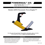
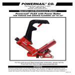
Powernail® Model 445FS STAPLER with Power Roller
445FS Power Roller
OPERATION AND MAINTENANCE MANUAL
MANUAL DE OPERACION Y DE MANTENIMIENTO
MANUEL D’INSTRUCTIONS ET D’ENTRETIEN
WARNING
Read this manual before you use this PowerStapler®. Follow all safety warnings and
instructions. If you are uncertain about the operation of the stapler, call us directly
at 1-800-323-1653 for assistance or contact the closest Powernail Dealer for help.
Please retain this information for future reference.
REV 2013.10.15
INTRODUCTION
The Model 445FS Stapler with Power Roller is a state-of-the-art pneumatic Powerstapler®
designed to bring flexibility and speed to tongue & groove flooring installation.
The Model 445FS Power Roller is designed for use with 2", 1-3/4" and 1-1/2" (15.5 gage)
Powerstaples® nails and can nail down from 3/4" to 5/8" tongue and groove hardwood flooring.
For superior pneumatic flooring tools, look to the company that has been the industry’s leader in
quality—POWERNAIL® COMPANY, INC.
INDEX
Index.....................................2
Warranty............................... 2
Safety Instructions................ 3
Operating Instructions.......... 4
Parts & Service.................... 5-7
Drive Blade Change..............6
Seal Replacement.................6-7
Parts List.............................. 8-9
Seal Locations Diagram....... 10
Schematic ........................... 11
Safety Labels........................12
Troubleshooting Chart......... 13
Depth Chart.......................... 14
Powernail Company Info...... 15
Accessory Products.............. 16
LIMITED WARRANTY
POWERNAIL® Company, Inc. warrants to its customer, and to the first end-use purchaser of
POWERNAIL flooring nailers purchased from an authorized POWERNAIL distributor, that
each serialized manufactured nailer by POWERNAIL®, for a period of 12 months from the date
of purchase, and with respect to the nailer/stapler body (specifically Models 200, 445, and 50P),
for a period of 10 years from date of purchase, (“warranty period”); shall be free of defects in
materials and workmanship and will meet POWERNAIL’s specifications in effect at the time of
Product shipment. POWERNAIL will repair or replace, at its option, any Powernailer® that does
not conform to this warranty. Claims must be made no later than fifteen (15) days after the end
of the warranty period. POWERNAIL will perform all repair or replacements itself or through
its authorized contractors. POWERNAIL is not responsible for shipping, labor or other direct or
indirect costs. Damage caused by abuse, misuse, unusual or excessive wear is excluded. Repair
or modification of the Products by unauthorized parties will void this warranty. The customer
is responsible for returning Products to POWERNAIL for verification of nonconformance.
Warranties for Products not manufactured by POWERNAIL are limited to warranties provided
to POWERNAIL by the manufacturer of such product that are assignable to customer.
THESE WARRANTIES AND REMEDIES ARE EXCLUSIVE OF ALL OTHERS, EXPRESS
OR IMPLIED. THE WARRANTIES OF MERCHANTABILITY AND FITNESS FOR
PURPOSE ARE EXPRESSLY EXCLUDED. IN NO EVENT SHALL POWERNAIL’S
LIABILITY FOR A WARRANTY CLAIM EXCEED THE PRICE PAID TO POWERNAIL
FOR THE NONCONFORMING PRODUCT, REGARDLESS OF THE FORM OR BASIS OF
THE CLAIM OR CAUSE OF ACTION.
2
SAFETY INSTRUCTIONS
Always use approved SAFETY GLASSES and EAR PROTECTION when operating this stapler. The
operator and others in the work area should always wear approved FRONT and SIDE eye protection
when operating this stapler. Eye protection will help guard against flying staples and debris, which could
cause severe eye injury.
EYE AND EAR PROTECTION should be used to prevent hearing damage when there are high noise
levels in the work area.
ALWAYS use ear plugs with a noise reduction rated at 29 db or highter at a construction site.
Stapler noise ratings are at LPA-1sd=90.6,
LWA-1sd=99.3 and LPA-1s,1m=86.3.
Stapler vibration rating: m/s2=3.05.
Always DISCONNECT THE AIR SUPPLY before making any adjustments, repairing, clearing jams or when the
stapler is not in use. Do not use on scaffolding or ladders and disconnect stapler from air supply when transporting
between installation areas.
Never attach the female end of a quick disconnect to the stapler. This will trap air inside the Stapler and permit it to
be discharged. Only the unrestricted male connection should be attached to the Stapler.
Stapler requires an air source that can continuously deliver 80 to 110 psi at 3-1/2 cubic feet of air per minute for
operation.
Normal air pressure should not exceed 120 psi or damage to the Stapler and seals may occur. Excess air
pressure can cause the Stapler to explode.
To prevent fire or explosion, use only regulated compressed air—do not use bottled gases of any kind (no oxygen
or combustible gasses) to power this Stapler.
Stapler is intended for use installing wood flooring and is not to be used for purposes not specified in the
operations manual.
The trigger is a safety device and should only be pulled when the Stapler is in proper Position on the work surface
and before the plunger is struck with the mallet. Do not tie or tape down the safety trigger as the Stapler could
discharge if dropped on the plunger. The Stapler will not fi re unless the trigger is pulled before the mallet blow. Do
not use the trigger safety as a lock up for the plunger then rack the wood using the locked up Stapler body. It will
severely damage the Mechanism and the Stapler. Use the mallet to rack the wood strip, not the Stapler.
Do not use any nails other than Powernail Powercleats Nails which are specifically designed for use in any
Powerstapler. Powercleats Nails are available in various lengths. Contact your Powernail Dealer for Powercleats
Nails.
Use only Powernail replacement parts in the repair or maintenance of this stapler. Parts or repair services are
available from the manufacturer or from agents authorised by the manufacturer. Repairs should be carried out
only by trained service personel in the field of fastener driving tools who will observe proper safety controls while
performing maintenace. Service personel should be qualified to to asses the safe working condition of fastener
driving tools.
Never place any part of the body in the discharge path of the Stapler when air is connected to the
Stapler. Always make sure Stapler is empty of cleats before connecting air hose so as to prevent any
accidental discharge from occurring.
Never leave the Stapler unattended while it is connected to an air supply.
Whenever air is connected to the Stapler, keep body parts away from the nail discharge path. Disconnect the air
line before making adjustments or repairs on the Stapler. Only connect air to an unloaded Stapler so as to prevent
accidental discharge.
POWERNAIL COMPANY, INC.
1300 Rose Road, Lake Zurich, IL 60047 US
Phone: 1-800-323-1653 OR 847-847-3000
www.powernail.com
3
OPERATING INSTRUCTIONS
To use the Model 445FS Power Roller, adjust the
stapler's FLEX foot to a sample of your flooring
(Figure 1). When the FLEX foot is adjusted to your
flooring, simply place the stapler on the floor and pull
the stapler back so the locating ears catch the edge
of the floor aove the tongue. Pull the safety trigger
and tap the plunger with the rubber-capped mallet
tolet the stapler drive and set the nail at the correct
45° angle. The Power Roller is designed to nail
from left-to-right. Consult the flooring manufacturers
recommended nailing schedule.
To Load the Powernail Flex:
Place up to one stick (100) of Powercleats® (18 gage)
nails, 1" , 1-1/4" , 1-1/2" or 1-3/4" long into the nail
channel feed slot. Pull back the spring loaded nail
pusher over the nails until it contacts the last nail and
slowly release the nail pusher.
To Unload
To remove nails from the nail channel, pull the two
round knobs on the nail pusher together. This will clear
it from the nail path. Then turn the nailer over so the
nails slide out of the channel.
FLEX Foot Adjustment:
Wood varies from one manufacturer to the next.
The different wood profiles may be due to height
and length of the flooring tongue and whether or
not there is a nail pocket.
First, loosen the two hex bolts under the FLEX
foot with the Allen Wrench supplied with the nailer.
(Figure 1.)
Next, set the nailer on a sample of your flooring
(see Figure 2).
Use the adjustment lever at the back of the nailer
foot to raise or lower the nailer to the wood. Match
the Adapter Foot Locating Ear so that it is pointing
into the 90° angle created by the tongue and the
top of the wood (see Figure 3). For wood with a
nail pocket, line up the Locating Ear so at the top
of the nail pocket.
When the adjustment lever is in the correct position
for your wood sample, tighten the two hex bolts to
lock the FLEX foot into place.
Always check your adjustment with a sample to
ensure the staple is driving into the nail pocket.
Figure 2.
Figure 1.
FLEX
Adjustment Lever
Hex Allen Wrench
1. Loosen 2 hex screws.
2. Raise or lower the FLEX to your wood sample.
3. Match the Locating Ear to the nail pocket.
4. Tighten 2 hex screws.
5. Test wood sample with new adjustment.
Figure 3.
ADAPTER FOOT
LOCATING EAR
Set the nailer on a sample of your flooring.
4
Raise the nailer foot above the tongue
to line up the nail pocket.
OPERATING INSTRUCTIONS, continued
WARNING: It is not necessary to hit the Stapler hard
to activate it. Never hit the Stapler with excessive
force or with the metal end of the mallet, this will
damage the Stapler.
DO NOT USE THE METAL END OF THE MALLET
TO STRIKE THE PLUNGER, use the rubber capped
end only.
Never use the Safety Trigger interlock to lock up
the plunger and rack the wood with blows to the
Stapler body. This will severely damage the safety
mechanism and Stapler. This abuse and damage is
not covered by the warranty.
Before each use, check all screws to be sure they are
tight. Shock and vibration can loosen screws. Do not
over tighten any screw.
AIR SUPPLY:
The air must be clean and dry. Dirty and/or wet air will
damage the Stapler.
Drywall Dust:
• Using Pneumatic PowerStaplers in drywall dust
conditions will dramatically decrease the life of the
Stapler.
• Drywall dust is abrasive, when cycled through
the Stapler it will cause excessive wear.
The air source must continuously deliver 80 to 110
psi at 3-1/2 cubic feet of air per minute to operate
the Stapler. For operation, connect a 1/4” minimum
internal diameter and clean air hose to the Stapler.
Be sure the air regulator is set at 90 psi. If the staple
is not countersunk below the surface of the wood, turn
up the air pressure, but not over 110 psi.
Check for air supply leaks that waste air and starve
the Stapler of air thereby reducing its performance.
There should be no orifice smaller than 1/4” in the air
path between the Regulator and the Stapler.
LUBRICATION:
You must lubricate the Stapler manually. The
frequency of lubrication is dependent upon the duty
cycle of the Stapler. Continuous duty requires more
frequent oiling than intermittent duty.
At least every eight (8) hours place two to four drops
of Air Tool Oil, supplied with your Stapler, into the
disconnected air line male connector attached to the
Stapler.
WARNING: Do not over lubricate the Stapler, excess
oil mist or drops will be vented with spent air when
over lubricated. Excess oil could stain the wood
flooring, walls or furnishings. Dry fire the Stapler,
without staples, to purge excess oil, before you begin
to staple down flooring. Before storing the Stapler,
lubricate and cycle the Stapler in insure internal parts
are oil protected from corrosion.
WARNING: Detergent oil is not recommended and may
damage the seals.
TO LOAD MODEL 445FS:
Place two sticks (90 PowerStaples) into the Staple
Channel feed slot. Pull back the spring loaded Staple
Pusher over the staples until it contacts the last staple
and slowly release the Staple Pusher.
TO UNLOAD MODEL 445FS:
To remove staples from the Staple Channel, pull the two
round knobs on the Staple Pusher together. This will
clear it from the staple path. Then turn the Stapler over
so the staples slide out of the channel.
PARTS & SERVICE:
When ordering parts include the part number, part
description, PowerStapler model and serial number. Be
sure to state the quantity of the part(s) required. Contact
your Powerstaple Dealer for the necessary parts.
WARNING: Never work on the Stapler if the air line is
attached. Always disconnect the air line from the Stapler
first.
Stapler DISASSEMBLY:
TO REPLACE RUBBER BUMPER (#20 or #65):
1. Disconnect the air supply
2. Remove the four (4) cap screws holding the Adapter
Foot, Foot and Staple Channel assembly to the main
Body (see illustration).
3. Pull the Rubber Bumper out of the cylinder bore.
Replace the old Bumper if it shows signs of wear or it is
split.
4. Reverse these steps to reassemble the Stapler. Be
sure to align the Driving Blade with the slot in the Staple
Channel Assembly while you reassemble the Stapler.
5
OPERATING INSTRUCTIONS, continued
NEVER FIRE THE Stapler WITHOUT THE RUBBER
BUMPER INSTALLED, IT WILL SEVERELY DAMAGE THE
STAPLER.
CHANGING A DRIVING BLADE (#14):
1. Disconnect the air supply.
2. Remove the four socket head cap screws(49) holding the
Adapter Foot(6), Foot(7) and Staple Channel AssemblY(42)
to the body.
3. Remove the Rubber Bumper(20).
4. Pull the Driving Blade(14) with pliers until the Piston(10)
is fully extended outward towards the bottom of the cylinder.
5. Use a 15/16” box wrench (Part #: 09-445-29768) to
unscrew the Driving Blade Jam Nut(50) and remove it.
Hold the Piston from turning while unscrewing the Jam Nut
by holding the piston hex with a 1-1/8” box wrench
(Part #: 09-445-29768).
6. Push out the 1/4” diameter blade retaining Dowel Pin(38)
and remove the broken Driving Blade stub.
7. Install a new Driving Blade in the slot and replace the
Dowel Pin(38). Screw on the retaining Jam Nut(50) using
the same tools. If the Jam Nut becomes worn and loose
after frequent removals, it should be replaced.
8. Check the fit, there should be some sideways movement
between the Driving Blade and the Jam Nut assembly.
This is desirable and helps the blade to align itself with the
mating parts.
9. Reassemble the components. Be sure to align
the Driving Blade with the slot in the Adapter Foot
Assembly(7,6).
4. Push Safety Yoke (#8) aside and unscrew the three
#10-32 cap screws holding the Plunger (#12) to the
Return Cylinder (#11).
5. Pull the Plunger up and out of the Stapler Body (#1)
cavity.
6. Remove the Return Cylinder O-Ring Gasket (#26)
located on the top of the Return Cylinder under the
Plunger.
7. Turn the Stapler over and remove the four cap
screws (#50), that fasten the Adapter Foot and Staple
Channel Assembly to the Stapler Body and lift the
Assembly off the Body.
8. Remove the Rubber Bumper (#20 or #65).
9. Pull the Driving Blade Assembly out of the Stapler
Body by pulling on the Driving Blade.
10. Hold the Piston Rod (#9) with an 11/16 socket over
its hex end opposite the Piston. Do not use pliers
or a vise anywhere on the metal parts, they can
damage the sealing surfaces.
11. Use box wrenches to remove the 5/8-18 Jam Nut
(#51). Remove the Dowel Pin (#38) and Driving Blade
(#14).
12. Unscrew the Piston from the Piston Rod using box
wrenches and separate the Piston, Piston Rod and
Return Cylinder.
TO REPLACE THE SEALS:
Rubber Seat (#19):
1. Remove the Cylinder Sleeve (#13). The Cylinder
Sleeve should slide out of the Stapler Body when you
pull out the Driving Blade Assembly.
SEAL REPLACEMENT: There are 7 seals that may
require replacement. We recommend that you have your
2. Remove the metal Support Ring (#17) and Rubber
POWERStaple Dealer replace the Seals.
Seat from inside the Stapler body. Note that the
SEAL KIT: You may choose to buy a Seal Replacement Kit chamfer on the inside of the Rubber Seat faces the
and replace the seals yourself. It is good practice to replace BOTTOM of the Stapler, do not reverse the direction of
the chamfer when you replace the Rubber Seat.
all seals at one time regardless if only one seal needs
replacement.
3. Replace the Rubber Seat, Support Ring and
Cylinder Sleeve. Be sure to re install the steel Cylinder
SEAL DESCRIPTION & NUMBER:
Sleeve with the chamfered inside edge facing the
1. Rubber Seat (#19)
BOTTOM of the Stapler
2. Plunger Seal Set (#21)
3. Piston U-Cup Lip Seal (#22)
Plunger Seal Set (#21):
4. Return Cylinder U-Cup Lip Seal (#23)
1. Remove the Teflon® Seal and its O-Ring expander
5. Piston Rod U-Cup Lip Seal (#24)
from the groove using a bent paper clip or pick. Be
6. Plunger Wiper Seal (#25)
sure not to scratch the inside walls of the seal groove
7. Return Cylinder O-Ring Gasket (#26)
with the wire hook.
To change Seals follow these procedures. Be sure the air
2. Clean out the seal groove. Place a new O-Ring into
line is disconnected from the Stapler first before making any the seal groove by stretching it over the Plunger body.
repairs. Consult the illustration for the name and location of
Make sure the O-Ring is not twisted in the groove.
the following component parts.
Place a new Teflon° Seal Ring into the seal groove
over the O-Ring.
SEAL REPLACEMENT REQUIRES REMOVAL OF THE
DRIVING BLADE ASSEMBLY:
3. Carefully push the Teflon®Seal Ring over the edge
1. Disconnect the air supply.
of the Plunger with your thumbs and into the groove.
2. Remove Rubber Plunger Cap (#18).
Do this as quickly as possible to reduce stretching of
®
3. Unscrew & remove Body Cap (#2).
6 the Teflon Seal Ring. DO NOT OVER STRETCH THE
OPERATING INSTRUCTIONS, continued
TEFLON® SEAL RING! Be sure the Teflon® Seal
Ring is centered all around the seal groove and not
twisted.
4. Wipe off the Seal surface with a clean rag and
lubricate it generously with Pneumatic Light Air Tool
Oil lubricant.
Piston U-Cup Lip Seal (#22):
1. Remove the old Piston U-Cup Lip Seal from the
Piston using a bent paper clip or pick, being careful
not to scratch the inside walls of the seal groove or the
edge of the Piston with the wire hook.
2. Clean out the seal groove. Place a new U-Cup Lip
Seal into the groove. Make sure the lips is not twisted
in the groove and the lips face the top of the Stapler
See the sketch below.
3. Carefully wipe off the U-Cup Lip Seal surface with a
clean rag and lubricate it generously with Pneumatic
Light Air Tool Oil lubricant.
Return Cylinder U-Cup Lip Seal (#23):
1. Use a bent paper clip or pick to remove the old
U-Cup Lip Seal from the internal seal groove inside
the Return Cylinder. Be careful not to scratch the
inside walls of the seal groove with the wire hook.
2. Clean out the seal groove. Place a new U-Cup Lip
Seal into the groove, be sure it is not twisted in the
groove. Be sure the lips are facing the inside of the
Return Cylinder as shown in the schematic (page 1011, 13).
WARNING: The U-Cup Lip Seals #23 and #24 look
alike, but they are different, DO NOT mix them up.
3. Carefully wipe off the Lip Seal surface with a clean
rag and lubricate it generously with Pneumatic Light
Air Tool Oil lubricant.
Piston Rod U-Cup Lip Seal (#24):
1. Remove the old U-Cup Lip Seal from the seal
groove with a bent paper clip or pick using care not
to scratch the inside walls of the seal groove with the
wire hook.
2. Clean out the seal groove and install a new U-Cup
Lip Seal. Be sure the Lips are facing the right direction
and are not twisted in the groove. See the sketch
below.
WARNING: The Lip Seals #23 and #24 look alike, but
they are different, DO NOT mix them up.
3. Carefully wipe off the seal surface with a clean rag
and lubricate it generously with Pneumatic Light Air
Tool Oil lubricant.
Plunger Wiper Metal Cap O-Ring (#25):
Return Cylinder O-Ring Gasket (#26):
1. Place a new O-Ring Gasket in the groove on top of the
Return Cylinder when you reassemble the Driving Blade
Assembly.
2. Wipe off the O-Ring Gasket seal surface and lubricate
it generously with Pneumatic Light Air Tool Oil lubricant.
REASSEMBLING THE Stapler:
1. Be sure the Rubber Seat, Support Ring and Cylinder
are installed in the Body and are facing the correct way.
2. All seal surfaces must be clean and lubricated
generously with Pneumatic Light Air Tool Oil lubricant.
Replace any part that shows signs of wear.
3. Use care when installing the seals into their respective
cavities. Be sure the Seals are contained in their
groove and do not come out as the parts slide together.
Generous cavity lead in chamfers have been provided to
help Seal installation.
4. Carefully insert the Piston Rod into the return Cylinder
and screw the Piston onto the rod. Be sure the Piston is
facing the correct way, ears up, hex down.
5. Assemble the Driving Blade, Dowel Pin and Jam Nut
on to the Piston Rod.
6. Insert the Driving Blade Assembly up into the bottom
of the Stapler Body Cylinder.
7. Be sure there is a new O-Ring Gasket in the top
groove of the Return Cylinder.
8. Insert the Plunger into the top cavity of the Body.
Line up the holes and install the three Plunger retaining
screws. It is important that the three #10-32 screws are
tight or air leakage will occur. Our recommendation is to
use 1-2 drops of blue Loctite® or similar on the 3 screws.
9. Position the Safety Yoke in the Plunger groove.
10. Install the Body Cap and Plunger Rubber Cap.
11. Turn the Stapler upside down. Install the Rubber
Bumper, Staple Channel Assembly and Adapter Foot. Be
sure to align up the Driving Blade with the slot in the Foot
before the Stapler is closed up.
12. NEVER FIRE THE Stapler WITHOUT THE RUBBER
BUMPER INSTALLED, IT WILL DAMAGE THE Stapler.
TO CLEAR A Staple JAM:
1. It helps to tap the Driving Blade back to the retracted
position before trying to remove a jammed staple. A
spare Driving Blade works best for this.
2. Try to pull the jammed staple out of the gate with a
pair of long nose pliers. If this does not work remove the
four (4) cap screws holding the Foot, Gate and Staple
Channel Assembly together.
3. Separate the Foot and gate with a screw driver just
enough to clear out the jammed staple.
4. Put thread locking compound on all screws and
For Step-by-Step Videos and Instructions,
reassemble the components.
1. Use a bent paper clip to pick out the felt Wiper
Seal out of its groove in the Body Cap (2).
2. Clean out the groove and insert the new O-Ring
(25) in to the groove in the metal body cap (2).
7
Visit our Web Site at: www.Powernail.com
MODELS 445FS POWER ROLLER PARTS LIST
Item # Part No.
DESCRIPTION
Qty Tuneup
Req’d
Kit
1
2
3
4
5
7
8
9
10
11
12
13
14
15
16
17
18
19
20
21
22
23
24
25
26
27
28
29
30
31
32
33
37
38
39
40
41
42
43
44
45
46
47
09-445-29320
09-445-29321
09-445-29703
09-445-29703.1
09-445-29704
09-445-29706
09-445-29707
09-445-29710
09-445-29711
09-445-29830
09-445-29831
09-445-29715
09-445-29303
09-445-29719
09-445-29720
09-445-29721
09-445-29722
09-445-29723
09-445-29724
09-445-29725
09-200-3026
09-200-3027
09-200-3028
09-445-29729
09-445-29731
09-445-29732
09-445-29732.1
09-445-29733
09-445-29326
09-445-29327
09-445-29328
09-445-29329
09-445-29739
09-445-29740
09-445-29815
09-445-29816
09-445-29331
09-445-29325
09-445-29305
09-445-29330
09-445-29756
09-445-29742
09-445-29743
BODY
CAP
HANDLE, LONG
HANDLE, SHORT
HANDLE, HALF
FOOT
SAFETY YOKE
PISTON ROD
PISTON
RETURN CYLINDER
PLUNGER
CYLINDER SLEEVE
DRIVING BLADE
BODY PLATE (.062 THICK)
TRIGGER
SUPPORT RING
RUBBER CAP
RUBBER SEAT
RUBBER BUMPER
PLUNGER SEAL SET
PISTON U-CUP SEAL
RETURN CYLINDER U-CUP SEAL
PISTON ROD U-CUP SEAL
PLUNGER WIPER METAL CAP O-RING
RETURN CYLINDER O-RING GASKET
TRIGGER CABLE, LONG
TRIGGER CABLE, SHORT
SAFETY YOKE SPRINGS
STAPLE PUSHER SPRING
#8-32 X 5/16 B.H.C.S. (CHANNEL)
#8-32 X 1/4 F.H.C.S. (CHANNEL)
STEEL STAPLE PUSHER
1/4” X 3/4” DOWEL PIN (TRIGGER)
1/4” X 1/2” DOWEL PIN (DRV. BLADE)
HANDLE, EXTRA LONG
TRIGGER CABLE, EXTRA LONG
#10-32 X 1/2” S.H.C.S. (STANDOFF)
TWO PART CHANNEL W/TWO B.H.C.S.
GATE PLATE
GATE
1/4 X 1 STANDOFF SPACE (CHANNEL)
1/4-20 X 7/8 S.H.C.S. (XL HANDLE ONLY)
1/4-20 X 1 S.H.C.S. (CAP)
1
1
1
1
1
1
1
1
1
1
1
1
1
1
1
1
1
1
1
1
1
1
1
1
1
1
1
2
1
2
1
1
1
1
1
1
1
1
1
1
1
2
4
48
09-445-29744
8
49
50
51
52
54
09-445-29747
09-445-29748
09-445-29317
09-445-29832
09-445-29758
1/4-20 X 3/4” S.H.C.S. W/PATCH
(4-HANDLE BASE,4-BEARING BLOCKS)
1/4-20 X 1-1/4 S.H.C.S. (FOOT)
5/8-18 JAM NUT (DRIVING BLADE)
#10-32 X 1” S.H.C.S. W/PATCH (FOOT)
#10-32 X 3/4 S.H.C.S. (PLUNGER)
1/4-20 SPLIT RING LOCK WASHER
8
4
1
4
1
4
Seal
Kit
TU
TU
TU
TU
TU
TU
TU
TU
TU
TU
TU
TU
TU
SEAL
SEAL
SEAL
SEAL
SEAL
SEAL
SEAL
Sold Separate or
Assembly #
F
S
A-6
A-7
A-6, A-7, A19
S, A-9
S
S, A-11
S, A-11
S, A-11
S, A-11
S
S, A-11
S
S,A-6, A-7, A-19
S
S
S, A-5, A-11
S, A-11
S, A-5, A-11
S, A-5, A-11
S, A-5, A-11
S, A-5, A-11
S, A-5
S, A-5, A-11
S, A-6
S, A-7
S
S, A-9, A-10
S, A-9
S, A-9, A-10
S, A-9, A-10
S, A-6, A-7, A-19
S, A-11
S, A-19
S, A-19
S, A-9
S, A-9
S, A-9
S, A-9
S, A-9
S
S
S
TU
S
S, A-11
S, A-9
S, A-11
S
MODELS 445FS POWER ROLLER PARTS LIST
Item #
56
57
58
71
72
73
75
76
77
78
79
81
84
85
86
87
88
89
91
93
94
96
97
98
99
Part No.
DESCRIPTION
09-445-29760
09-445-29836
09-445-29313
09-445-29334
09-50P-3072
09-50P-3073
09-50P-3075
09-50P-3076
09-50P-3077
09-50P-3078
09-50P-3079
09-445-29875
09-50P-3084
09-50P-3085
09-50P-3086
09-50P-3087
09-50P-3088
09-50P-3089
09-445-29876
09-50P-3093
09-445-297441
09-445-29801
09-445-29802
09-50P-3097
09-445-29878
#8-32 X 3/8 B.H.C.S (CABLE)
#10-32 X 3/8” S.H.C.S. (GATE)
#6-32 X 1/2” F.H.C.S. (GATE)
FLEX FOOT BRACKET (445FS)
FLEX FOOT CAM
FLEX FOOT CAM PLATE
SHCS 1/4-28 X 1.25"
WASHER .281 IDX.62 ODX.051" T
BHCS #10-32 X .50"
1/4 SH DIA X .50" SH. BOLT (W/PATCH)
BELLEVILLE DISC SPRING
ROLLER FLEX FOOT (445)
ROLLER 10MM SH DIA X 16MM SH BOLT
ROLLER SM BEARING BLOCK (LEFT SIDE)
ROLLER BEARING PIN
#10-32X.25” SET SCREW
ROLLER COVER LG (COVER ONLY)
DOWEL .125 DIA X .38
ROLLER ADAPTER FOOT (445)
ROLLER SM BEARING BLOCK (RIGHT SIDE)
1/4-20 X 3/4 SHCS (HANDLE HALF)
HEX WRENCH 3/16 (FLEX FOOT)
HEX WRENCH 5/32
LARGE ROLLER BEARING WITH MOLDED COVER
SMALL ROLLER BEARING WITH MOLDED COVER
QtyReq
1
2
2
1
1
1
2
2
2
1
1
1
4
1
2
2
4
4
2
1
2
1
1
4
2
TU
TU
TU
AVAIL
S
S, A-9
S, A-9
S
S
S
S
S
S
S
S
S
S
S
S
S
S, A-1
S
S
S
S
A-24
A-24
S, A-2
S, A-2
KEY: S=Sold Separately, A= Sold as part of assembly, TU=Tune-up Kit, F=Factory replacement only, or Seal Kit.
Model 445FS Power Roller Assemblies, Kits and Accessories
ITEM # PART NO.
A-2
A-4
A-5
A-6
A-9
A-10
A-11
A-15
A-24
A-25
DESCRIPTION
09-RB445A
09-445-29757A
09-200-3058A
09-445-29759A
09-445-29365A
09-445-29366A
09-445-29364A
09-445-29768
09-AW-445
09-445FS-TU-KIT
COMPLETE ROLLER BEARING SET WITH TIRES (2 SM FRONT + 4 LG MAIN)
6 OZ. AIR TOOL OIL
SEAL KIT (1 EACH OF ALL SEALS)
LONG HANDLE ASSEMBLY
STAPLE CHANNEL ASSEMBLY
STAPLE PUSHER ASSEMBLY
DRV. BLADE ASSEMBLY W/RUBBER SEAT
BOX WRENCH - 2 ENDS: 15/16" & 1-1/8" (2 REQ)
ALLEN WRENCH SET (3/16 FLEX FOOT AND 5/32)
MODEL 445FS TUNE UP KIT (XLL, XLS, LL, LS, SL, SS)
For this parts list and other Powernailer schematics, please visit the
Powernail Parts Store at http://www.powernail.com
9
QTY REQ
1
1
1
1
1
1
1
2
1
1
3. Separate the Foot and gate with a screw driver just enough to clear out the jammed nail.
4. Put thread locking compound
on all screws and
reassemble
components.
Pneumatic
Seal
Partthe
Numbers
10
and Locations
SCHEMATIC - Model 445FS Power Roller
94
94
51
93
99
95
54
91
49
86
84
71
88
98
77
81
73
72
76
89
For Step-by-Step Videos and Instructions,
Visit our Web Site at: www.Powernail.com
85
48
87
FLEX Power Roller Conversion Parts.
79 78
Kits Available - For use on the Model 445FS Stapler
Seal Kit
(1 Each Of All Seals)
Part #: 09-2003058A
Schematic #'s: 19,21,22,23,24,25,26
Tune-up Kit
Part #: 09-445FSTUKIT
Schematic #'s: 14,18,19, 21,22,23,24,25,26,38,43,44,
50,57(2),58(2)
11
75
NAILER SAFETY DECALS
CAUTION
1. Do not tie down the
Safety Trigger
2. To prevent accidental
discharge
never attach air hose
to loaded Nailer.
Caution:
To
Prevent
Accidental
Discharge
Never
Attach
Air Hose
To
Loaded
Nailer
↑
CAUTION:
R
E
L
O
A
D
Lubricate
Nailer with
2-4 drops of
Industrial Light
Oil for every
8 hours of use.
Refill the nail channel with a
clip of Powercleats when empty.
Pull the Nail-Pusher assembly
to the back of the channel when
cleats are reloaded.
Nailer is activated by striking the plunger. Do not work on
scaffolding, ladders, elevated or uneven surfaces where the
nailer could fall and self-activate. Do not leave air attached to
the Nailer when moving from one install location to another.
12
PowerStapler 445FS Trouble Shooting Chart
PROBLEM
1
POSSIBLE CAUSE
SOLUTION
1. Zero of Low air pressure
Check air supply for 80 psi minimum to 110 psi maximum
2. Lack of lubrication
Manually lubricate through male air inlet fitting
3. Excessive dirt inside Stapler
Driving
blade does 4. Bent or burred driving blade
not retract 5. Seals worn out
6. U-Cup Lip Seals installed upside down
Disassemble and clean
Replace driving blade (14)
Replace all seals (Seal Kit A-5)
Replace all seals (Seal Kit A-5)
7. Seals need to be seated — dry fire Stapler
2
3
4
5
Driving
blade
retracts
slowly
1. Low air pressure
Turn up air pressure to 80-110 psi max
2. Lack of lubrication
Manually lubricate through male air inlet fitting
3. Air supply restricted by small orifice
Use 1/4" minimum diameter air fittings
4. U-Cup Lip Seals installed upside down
Replace all seals (Seal Kit A-5)
5. Excessive dirt inside nailer
Disassemble, clean and lubricate
1. Low air pressure
Turn up air pressure to 80-110 psi max
2. Broken Driving Blade
Replace Driving Blade (14)
Staple is not
3. Stapler hit hard surface
countersunk
Stapler
leaks air
Move from obstruction
4. Driving blade jam nut came loose
Retighten or replace jam nut (50)
5. Worn out gate
Replace gate (44)
1. Air supply fittings loose
Tighten all air line fitting connections
2. Dry wall dust in Stapler
Rebuild Stapler
3. Excess air pressure blew out seals
Check air supply for 110 psi maximum—replace all seals
4. Plunger screws loose
Tighten 3 plunger screws (52)
5. Cracked or damaged body
Replace body (1)
6. Seals worn out
Replace all seals (Seal Kit A-5)
7. Seals need to be seated
Dry fire Stapler
1. Operated without rubber bumper installed
Bottom
of stapler
cracked off 2. Excessive air pressure used
Replace damaged parts
Replace damaged parts
1. Not using Powerstapler™ Staples
Use Powerstapler™ Staples only (2”,1-3/4”,1-1/2” Lengths)
2. Continued use after a short hit
Clear staple immediately after short hit
3. Staple pusher damaged or spring broken
Replace staple pusher assembly (A-10)
Staples jam
4. Staple channel loose
6
in nailer
Tighten staple channel retaining screws (49, 51)
5. Bent staple stuck in staple guide
Disassemble and clear out bent staple
6. Hit another set staple or hard object
Move from obstruction
7. Stapler gate worn out
Replace staple gate (44)
Plunger 1. Safety trigger not being depressed
locked
7
up—won't
2. Lack of lubrication
move or fire
Replace damaged plunger, safety yoke and
plunger seal (12, 8, 21)
Manually lubricate through male air inlet fitting
13
POWERSTAPLE DEPTH CHART
This chart will assist you in determining the proper length
of PowerStaple® to use for various thicknesses of flooring.
Approximate vertical penetration of the PowerStaple under the
hardwood floor is shown for each application. This is only a
guide. Results should be tested in the field before proceeding.
33/32" FLOORING
3/4" FLOORING
5/8" FLOORING
1/2" FLOORING
1-1/8"
1"
3/4"
3/4"
UNDERLAYMENT
31/32"
UNDERLAYMENT
2” POWERSTAPLE®
15.5 GAGE
2” POWERSTAPLE®
15.5 GAGE
UNDERLAYMENT
2” POWERSTAPLE®
15.5 GAGE
31/32"
3/4"
2” POWERSTAPLE®
15.5 GAGE
3/4" FLOORING
5/8" FLOORING
1/2" FLOORING
31/32"
7/8"
3/4"
UNDERLAYMENT
1-3/4” POWERSTAPLE®
15.5 GAGE
3/4"
UNDERLAYMENT
1-3/4” POWERSTAPLE®
15.5 GAGE
13/16"
1-3/4” POWERSTAPLE®
15.5 GAGE
3/4"
UNDERLAYMENT
3/4" FLOORING
5/8" FLOORING
1/2" FLOORING
3/4"
1-1/2” POWERSTAPLE®
15.5 GAGE
3/4"
UNDERLAYMENT
21 32
1-1/2” POWERSTAPLE®
15.5 GAGE
"
3/4"
UNDERLAYMENT
14
19/32"
1-1/2” POWERSTAPLE®
15.5 GAGE
3/4"
UNDERLAYMENT
3/4"
UNDERLAYMENT
POWERNAIL COMPANY, INC.
1300 Rose Road, Lake Zurich, IL 60047 US
Phone: 1-800-323-1653 or 847-847-3000
www.powernail.com
15
Visit www.Powernail.com
• Dealer Locator
• Rental Locator
• Parts Store
• Product Information
• Repair Tech Videos
• Cool Tools Cleat Calculator
• Cleat Depth Chart
• Training Schools
Featured Accessory Products
Powerjack® Model 500
Truly a Tinker's TOOL, the POWERJACK Model 500 is
designed to push or pull flooring strips into place and hold
them tightly. The PowerJack Model 500 self adjusts from
5/16” to 3/4" thickness flooring. It can be used to either push
or pull wood flooring strips into place and ratchets tightly
for hands free operation. The base of the PowerJack 500
has mounting holes for mid-floor use. Simply screw nail the
PowerJack 500 to your sub floor -in front of your flooring
strips -and ratchet the flooring strips tight. Also great for under
cabinet and kick plate installation.
Part number: 06-99650
The PowerPalm™
"The PowerPalm is the industries best solution to blind nailing
close to the wall. Saves both, time and money!"
Pressure activated...simply press down, and let the tool do the
work. The Power Palm will allow blind nailing closer to the
wall and reduce the amount of face nailing. "Blind nail, top
nail...tight spots and corners, the PowerPalm gets them all!"
Featuring 360 degree swivel tip for fitting awkward or tight
spaces. Magnetic cleat holder keeps nail in position. Uses
both 16 gage and 18 gage Powercleats–Use the same fastener
throughout your install! Part number: 02-PALM001
Powernailer® TOOL BAG™
The TOOL BAG holds all Powernailer® configurations
including the FLEX and POWER ROLLER models.
The Powernail TOOL BAG is built tough with a double
wall of padded industrial nylon to protect your tools.
Corners are reinforced with leather for durability.
Zippered storage pouch on the inside (12” x 6”).
The Tool Bag has two durable handles which can be
used for carrying over your shoulder.
Dimensions: 20” base, 7” deep and 20” Tall.
Part number: 06-99201
16
Powerjack
Model 500
Closest you
can get to
the wall!
Pneumatic PowerPalm™
TOOL BAG