1
Environmental Measurement
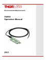
TSP01
Operation Manual
2012
Version: 1.0
Date:
09.08.2012
Copyright © 2012 Thorlabs
Contents
Foreword
2
1 General Information
3
1.1 Safety
1.2 Ordering Codes and Accessories
1.3 Requirements
1.3.1 Hardware Requirements
1.3.2 Software Requirements
2 Installation
2.1 Parts List
2.2 Getting Started
2.3 Installing Software
3 Operating Instruction
3.1 Quick Start
3.2 Detailed GUI Description
3.2.1 Controls
3.2.2 Settings
3.2.3 Tab Measurement
3.2.4 Tab Table
3.2.5 Tab Graph
3.2.6 Graph Display Option Menues
3.2.7 Logging Panel
3.2.8 Save Data
3.2.9 Load Data
3.2.10 Export Settings
3.2.11 Import Settings
3.2.12 Device Information
4 Write Your Own Application
4.1 Driver Installation and Location
4.2 Command Reference
4.2.1 IEEE488.2 Common Commands
4.2.2 SCPI Command Reference
5 Maintenance and Service
5.1 Version Information
6 Appendix
6.1
6.2
6.3
6.4
Technical Data
Certifications and Compliances
List of Acronyms
Thorlabs Worldwide Contacts
3
3
3
3
3
4
4
4
4
11
12
15
15
16
17
17
18
18
19
20
20
21
21
22
23
24
27
27
28
31
31
32
32
33
34
35
We aim to develop and produce the best solution for your application
in the field of optical measurement technique. To help us to live up to
your expectations and improve our products permanently we need
your ideas and suggestions. Therefore, please let us know about
possible criticism or ideas. We and our international partners are
looking forward to hearing from you.
Thorlabs GmbH
Warning
Sections marked by this symbol explain dangers that might result in
personal injury or death. Always read the associated information
carefully, before performing the indicated procedure.
Attention
Paragraphs preceeded by this symbol explain hazards that could
damage the instrument and the connected equipment or may cause
loss of data.
Note
This manual also contains "NOTES" and "HINTS" written in this form.
Please read these advices carefully!
2
© 2012 Thorlabs
1 General Information
1
General Information
The TSP01 is a device in the size of a USB thumb drive that can be plugged to any free USB
port for reading up to three different temperature values and relative humidity.
The combined humidity and temperature sensor is embedded into the USB stick, a second
NTC temperature sensor is included and can be connected to the housing. A third optional
temperature sensor can be plugged to the USB housing. External temperature sensors can be
Thorlabs TSP-TH or any other NTC type sensors. The software allows to enter individual NTC
parameters, such as R0 (reference resistance), T0 (reference temperature) and the B
coefficient.
The data can be displayed in the GUI or can be embedded into existing software, e.g. Thorlabs
Beam Profiler Software.
1.1
Safety
Attention
All statements regarding safety of operation and technical data in this instruction
manual will only apply when the unit is operated correctly as it was designed for.
All modules must only be operated with proper shielded connection cables.
Only with written consent from Thorlabs may changes to single components be carried
out or components not supplied by Thorlabs be used.
This precision device is only serviceable if properly packed into the complete original
packaging including the plastic foam sleeves. If necessary, ask for a replacement
package.
1.2
Ordering Codes and Accessories
TSP01
TSP-TH
1.3
Temperature and Humidity USB Sensor Probe with external temperature sensor
External temperature probe for TSP01
Requirements
1.3.1 Hardware Requirements
CPU: 1 GHz or higher
RAM: 512 MB or more
Graphic card with at least 32 MB memory
Hard disc with at least 100 MB free storage space
Free USB2.0 port
1.3.2 Software Requirements
The TSP01 software is compatible with the following operating systems:
Windows ® XP (32-bit) SP3
Windows ® Vista (32-bit, 64-bit)
Windows ® 7 (32-bit, 64-bit)
For operation of the TSP01, also an NI-VISA (version 5.1 or higher) is required. This NI-VISA
engines comes with the Thorlabs TSP01 installation CD, but can be downloaded also from
National Instruments' website www.ni.com.
© 2012 Thorlabs
3
TSP01
2
Installation
2.1
Parts List
Inspect the shipping container for damage.
If the shipping container seems to be damaged, keep it until you have inspected the contents
and you have inspected the TSP01 mechanically and electrically.
Verify that you have received the following items within the package:
1. TSP01
Temperature and Humidity USB Sensor Probe
2. TSP-TH External Temperature Probe for TSP01
3. USB Extension Cable, 2m
4. CD with TSP01 software and drivers
5. Quick Start Instruction
2.2
Getting Started
Attention
Please do not connect the TSP01 prior to install software! The probe won't be recognized
correctly and will not work as intended.
2.3
Installing Software
Hereinafter, the installation to Windows 7 operating system is explained.
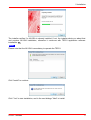
Insert the CD and select "Install Software" from the start up panel.
If the CD does not start automatically, please start the installation manually from
[CD Drive]:\autorun\autorun.exe
4
© 2012 Thorlabs
2 Installation
The installer verifies if a NI-VISA is already installed. If not, the installer alerts you about that
and requires NI-VISA installation, otherwise it continues with TSP01 application software
installation 9
Note
Please note that the NI-VISA is mandatory to operate the TSP01.
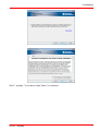
Click "Install" to continue
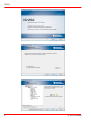
Click "Yes" to start installation, and in the next dialogs "Next" to install.
© 2012 Thorlabs
5
TSP01
6
© 2012 Thorlabs
2 Installation
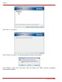
Click "I accept..." if you do so, then "Next >" to continue.
© 2012 Thorlabs
7
TSP01
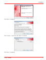
Click "Next >" to continue.
Click "Finish" to continue. You will be prompted to restart the computer.
Click "Restart", leave CD in the drive. After the restart, the TSP01 software installation
automatically resumes:
8
© 2012 Thorlabs
2 Installation
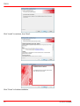
Click "Next >" to continue.
Click "I accept..." if you do so, then "Next >" to continue.
Click "Next >" to continue.
© 2012 Thorlabs
9
TSP01
Click "Install" to continue, then "Next".
Click "Finish" to finalize installation.
10
© 2012 Thorlabs
3 Operating Instruction
3
Operating Instruction
After installation of the software connect the TSP01 to a free USB2.0 port.
The operating system recognizes a new
device and automatically installs the
device drivers.
Start the GUI from the desktop icon.
At the first connect, you will be prompted to select the
preferred unit for temperature display. Click "OK" to
confirm your choice. The software now automatically
connects to the TSP01, and the actual temperature and
relative humidity, measured on the internal sensor, are
displayed. If an external sensor is connected, it will be
recognized and enabled automatically; it's temperature
will be displayed then.
© 2012 Thorlabs
11
TSP01
3.1
Quick Start
The Quick Start gives a short overview on how to use the TSP01 software.
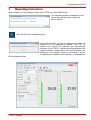
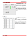
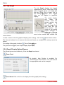
Tab Measurement
In the tab Measurement the actual measurement
values of all enabled sensors are displayed in
numerical values and within a bar.
The bar indication range can be set individually in
the Settings menu (see extended manual).
Additionally, for each bar 2 limits can be defined,
controlling the bar color (blue - green- red)
depending on the actual value with respect to
these 2 limits.
12
© 2012 Thorlabs
3 Operating Instruction
Logging panel
Logging Control: Three modes can be set: manual start/stop,
timed logging or logging of a number of samples.
Measurement Interval: The logging interval (time between two
measurements) can be set from 1 to 10000 seconds.
Averaging: When averaging is unchecked, a single measured
value per selected measurement interval will be logged. By
checking this box, all values that are measured each second will
be averaged over the period of the selected measurement interval
and only this average value will be logged. That means per
measurement interval for both options one single value will be
logged only.
Time Axis Scale: 3 selections are available: time in seconds, time
in hours:minutes:seconds and time stamp (date an time). The
complete time stamp (date and time) will be displayed only in the
Table tab.
Start / Stop Logging This is a toggle button to start / stop logging
process.
Results In this pane logging statistics are displayed.
Tab Table
In the tab Table all logged data vs. time are
displayed numerically.
Column description:
Time: format as selected for "Time Axis Scale"
Results: The values from all sensors are
displayed. If an external sensor is not enabled or
not present, the values show "--.---"
Remarks: empty if no error occurred, otherwise an
error message will be displayed
© 2012 Thorlabs
13
TSP01
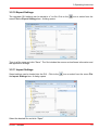
Tab Graph
In the Graph all logged data vs. time are
displayed, if enabled (Show Plot in Settings
menu)
Temperature: up to 3 curves can be displayed:
blue for internal sensor, green for external sensor
TH1 and red for external sensor TH2.
Rel. Humidity: If enabled (Show Plot in Settings
menu) it will show in black color the rel. humidity
value vs. time.
Settings panel
To adjust settings, click to the
icon or select
"Settings" from the "Option" menu.
From this panel you can adjust the appearance of
the GUI, change thermistor settings and enable/
disable sensor. Tool tips appear when moving the
mouse pointer over the appropriate parameter.
In the following section the functionality is described in detail.
14
© 2012 Thorlabs
3 Operating Instruction
3.2
Detailed GUI Description
The Graphic User Interfaces automatically connects to the detected TSP01. The software
starts with the most recent settings and configuration.
3.2.1 Controls
TSP01 GUI Controls
The following table summarizes the function of controls. For detailed information, click to the
text in the Function column.
Menu
Menu Topic
Icon
Function
Load Data
Loading measurement data from
a file 20
Save Data
Saving measurement data to a
file 20
Import Settings
Import configuration file
Export Setting
Export configuration to a file
Exit
Exit GUI
21
21
Connect Device
Disconnect Device
Device Information
Zoom Panel *)
Zoom Home *)
Hide Grid *)
© 2012 Thorlabs
-
Recalls TSP01 info
22
Opens Zoom Dialog
*) (Graph axes) 18
panel
Resets zoom of Graph display
*)
18
Hide /show grid in Graph display
*)
18
Clear Measurement Data
Clears all logged data
Settings
Opens Settings dialog panel
16
15
TSP01
Menu
Menu Topic
Icon
Function
Visit Thorlabs Website
View License Agreement
About
Displays info on the software
31
*) Option is displayed only when Graph tab is selected
3.2.2 Settings
The Settings dialog is almost self explaining,
please note the tool tips which appear when
moving the mouse pointer over an item.
The upper two frames contain settings for the
TSP01 internal sensor which combines a
temperature and a humidity probe, while lower
frames are related to external thermistor(s).
Temperature Units: Select the required unit
(°C, °F or K)
Enable a sensor: Check the box at the bold
sensor description. Default settings: Internal
sensors enabled, external enabled if
recognized.
Show Plot in Graph Tab: Check this box to
enable display of logged values in graph tab.
Use this sensor as Reference: When
checking this box, all sensors' values will be
equalized to the value of the reference sensor
by adding a positive or negative offset. This
individual offset is displayed for each affected
sensor. Unchecking this box returns all sensors
to display of the real temperature.
Offset: Additionally, for each sensor an
individual offset can be entered manually.
Thermometer (Hygrometer) Bar Range:
Upper and lower limits of the bar display in
Measurement tab. The default value depends on the actual measured values at start of the
application or connect to a TSP01.
Temperature (Humidity) Window: The color of the bar display can change depending on
the actual measured value. Low and High are the thresholds for changing from blue to
green or green to red, respectively.
Measurement Range: This is the physical range of the sensor, it's not editable. For the
internal combined sensor, the ranges are fixed, for external thermistors the range is
calculated from entered R0, T0 and B values.
16
© 2012 Thorlabs
3 Operating Instruction
3.2.3 Tab Measurement
Tab Measurement displays by default
the actual measurement results for
internal sensors and recognized external
thermistor sensors. Displayed sensors
can be hidden, see Settings 16 .
For each sensor, the result is displayed
numerically and on a vertical bar. The
bar color changes depending on the
value. The thresholds for color change
as well as upper and lower limit of the
bar can be adjusted in the Settings 16
panel.
3.2.4 Tab Table
In the tab Table the logging results are
displayed.
The first column contains the time in the
format as selected in the Logging panel 19
(time in seconds / days:hours:minutes:
seconds or complete time stamp).
The next columns display the logged data
from all sensors. If an external sensor is not
recognized
(not
connected),
it's
measurement values will be displayed as "-.---".
© 2012 Thorlabs
17
TSP01
3.2.5 Tab Graph
The tab Graph displays the logged
measurement values. Data base is the
table of logged values, it is linked with
the box "Show Plot in Graph Tab" in
the Settings 16 panel. Thus, logged
data can be toggled in graphical
display.
The graph display
can
easily
be
zoomed: move the
mouse pointer into
the
graph
it
changes to . Push
and hold the left
mouse button - the
center of the mouse
pointer changes to
white color. Drag a
rectangle over the
area to be zoomed and release the
mouse button.
In order to return to the full graphical display (auto scaling) , click to the
Zoom Home button.
The time axis shows time in [sec] or [hh:min:sec] formats, a complete time stamp cannot be
shown.
For scaling of the graph, click the
Zoom Dialog
The grid can be toggled, see Graph Display Options
18
icon.
19
.
3.2.6 Graph Display Option Menues
The following icons are visible only, if the tab Graph is selected.
Zoom Panel
By default, Auto Scaling is enabled. By
unchecking the "Auto Scale..." box, the limits of
the appropriate axis can be changed.
Zoom Home Click to this icon to display the entire graph (auto scaling)
18
© 2012 Thorlabs
3 Operating Instruction
Show / Hide Grid This button toggles the grid of the graph display on/off.
Above functions can be reached via the Options drop-down menu as well.
3.2.7 Logging Panel
This is the control panel for recording of temperature(s) and/
or humidity over time.
Measurement Interval: The logging interval (time
between two measurements) can be set from 1 to 10000
seconds.
Averaging: When averaging is unchecked, a single
measured value per selected measurement interval will be
logged. By checking this box, all values that are measured
each second will be averaged over the period of the selected
measurement interval and only this average value will be
logged. That means per measurement interval for both
options one single value will be logged only.
Logging Control: 3 modes can be set: manual start/
stop, timed logging or logging of a number of samples.
Time Axis Scale: 3 selections are available: time in
seconds, time in hours:minutes:seconds and time stamp
(date an time). The complete time stamp (date and time)
will be displayed only in the Table tab.
Start / Stop Logging This is a toggle button to start / stop
logging process.
Results In this pane logging statistics are displayed.
Start of Measurement: time in hh:min:sec
Duration of measurement: a value will be displayed only in time or samples logging modes
Samples of measurement: a value will be displayed only in time or samples logging modes
Below the progress bar, numerical values (minimum, maximum, average and fluctuation). All
values are updated with each new logged value. Fluctuation is the difference between Min
and Max.
© 2012 Thorlabs
19
TSP01
3.2.8 Save Data
Logged data can be saved to a tab separated *.txt file. Click to the
menu File the Save Data item. A dialog opens:
icon or select from the
Type in a file name and click "Save". The file includes a header with sensor and software
information, application settings and the logged measurement data.
3.2.9 Load Data
Saved data can be loaded into the GUI. Click to the
Load Data item. A dialog opens:
icon or select from the menu File the
Select the desired file and click "Open". The file is loaded into the GUI and will be displayed
with all appropriate application settings, as saved in the file header.
20
© 2012 Thorlabs
3 Operating Instruction
3.2.10 Export Settings
The complete GUI settings can be saved to a *.txt file. Click to the
menu File the Export Settings item. A dialog opens:
icon or select from the
Type in a file name and click "Save". The file includes the sensor and software information and
the application settings.
3.2.11 Import Settings
Saved settings can be loaded into the GUI. Click to the
the Import Settings item. A dialog opens:
icon or select from the menu File
Select the desired file and click "Open".
© 2012 Thorlabs
21
TSP01
3.2.12 Device Information
The Device Information menu retrieves information on the connected TSP01:
22
© 2012 Thorlabs
4 Write Your Own Application
4
Write Your Own Application
In order to write your own application, you need a specific instrument driver and some tools for
use in different programming environments. The driver and tools are being installed to your
computer during software installation and cannot be found on the installation CD.
In this section the location of drivers and files, required for programming in different
environments, are given for installation under Windows XP (32 bit) and Windows 7 (32 and 64
bit).
Note
TSP01 software and drivers are 32 bit applications. As for this reason, in 32 bit systems, they
are installed to
“C:\Program Files”
while in 64 bit systems - to
“C:\Program Files (x86)”
In the table below you will find a summary of what files you need for particular programming
environments.
Programming environment Necessary files
C, C++, CVI
*.h (header file)
*.lib (static library)
C#
.net wrapper dll
Visual Studio
*.h (header file)
*.lib (static library)
or
.net wrapper dll
LabView
*.fp (function panel) and NI VISA instrument driver
Beside that, LabVIEW driver vi's are provided with the
*.llb container file
Note
All above environments require also the NI VISA instrument driver dll !
In the next section the location of above files for all hardware, supported by TSP01 drivers, is
described in detail.
© 2012 Thorlabs
23
TSP01
4.1
Driver Installation and Location
NI VISA Instrument driver:
C:\Program Files\IVI Foundation\VISA\WinNT\Bin\TLTSP_32.dll
C:\Program Files\IVI Foundation\VISA\WinNT\Bin\TLTSP_64.dll
Note
This instrument driver is required for all development environments!
Source file
C:\Program Files\IVI Foundation\VISA\WinNT\TLTSP01\TLTSP.c
Header file
C:\Program Files\IVI Foundation\VISA\WinNT\include\TLTSP.h
Static Library
C:\Program Files\IVI Foundation\VISA\WinNT\lib\msc\TLTSP_32.lib
C:\Program Files\IVI Foundation\VISA\WinNT\TLTSP01\TLTSP_32.lib
C:\Program Files\IVI Foundation\VISA\WinNT\Lib_x64\MS\TLTSP_64.lib
Function Panel
C:\Program Files\IVI Foundation\VISA\WinNT\TLTSP01\TLTSP.fp
Online Help for NI VISA Instrument driver:
C:\Program Files\IVI Foundation\VISA\WinNT\TLTSP01\Manual
NI LabVIEW driver
C:\Program Files\National Instruments\LabVIEW xxxx\Instr.lib\TLTSP…
…\TLTSP.llb
(LabVIEW container file with driver vi's and an example. "LabVIEW xxxx" stands for actual
LabVIEW installation folder.)
.net wrapper dll
C:\Program Files\Microsoft.NET\Primary Interop Assemblies…
…\Thorlabs.TSP.dll
24
© 2012 Thorlabs
4 Write Your Own Application
Example for C
Project file (NI-LabWindowsTM/CVI 2010):
C:\Program Files\IVI Foundation\VISA\WinNT\TLTSP01\Examples\CVI_C\…
…sample.prj
Source file:
C:\Program Files\IVI Foundation\VISA\WinNT\TLTSP01\Examples\CVI_C\…
…sample.c
Executable sample demo:
C:\Program Files\IVI Foundation\VISA\WinNT\TLTSP01\Examples\CVI_C\…
…sample.exe
Example for C++
Solution file:
C:\Program Files\IVI Foundation \visa\WinNT\TLTSP01\Examples\…
…MS_VISUALCPP\TSP01_CPP_Sample.sln
Project file:
C:\Program Files\IVI Foundation \visa\WinNT\TLTSP01\Examples\…
…MS_VISUALCPP\TSP01_CPP_Sample\TSP01_CPP_Sample.vcxproj
Executable sample demo:
C:\Program Files\IVI Foundation\VISA\WinNT\TLTSP01\Examples\…
…\MS_VISUALCPP\Output\TSP01_CPP_Sample.exe
Example for DotNet
Example for C#
Solution file:
C:\Program Files\IVI Foundation \visa\WinNT\TLTSP01\Examples…
…\MS.NET_CS\TSP01_CSharp_Sample.sln
Project file:
C:\Program Files\IVI Foundation \visa\WinNT\TLTSP01\Examples…
…\MS.NET_CS\TSP01_CSharp_Sample\TSP01_CSharp_Sample.csproj
Executable sample demo:
C:\Program Files\IVI Foundation\VISA\WinNT\TLTSP01\Examples…
…\MS.NET_CS\Output\TSP01_CSharp_Sample.exe
© 2012 Thorlabs
25
TSP01
Example for LabView
C:\Program Files\National Instruments\LabVIEW xxxx\Instr.lib\TLTSP…
…\TLTSP.llb
(LabVIEW container file with driver vi's and an example. "LabVIEW xxxx" stands for actual
LabVIEW installation folder.)
26
© 2012 Thorlabs
4 Write Your Own Application
4.2
Command Reference
4.2.1 IEEE488.2 Common Commands
Common commands are device commands that are common to all devices according to the
IEEE488.2 standard. These commands are designed and defined by this standard. Most of the
commands are described in detail in this section. The following common commands associated
with the status structure are covered in the “Status Structure” section: *CLS, *ESE, *ESE?,
*ESR?, *SRE, *SRE?, *STB?
Command summary
Mnemonic
*CLS
*ESE <NRf>
*ESE?
*ESR?
*IDN?
*OPC
Name
Clear status
Event enable command
Event enable query
Event status register query
Identification query
Operation complete command
*OPC?
Operation complete query
*RST
*SRE <NRf>
*SRE?
*STB?
*TST?
*WAI
Reset command
Service request enable command
Service request enable query
Status byte query
Self-test query
Wait-to-continue command
Description
Clears all event registers and Error Queue
Sets the Standard Event Enable Register
Returns the Standard Event Enable Register
Returns and clear the Standard Event Register
Returns the unit’s identification string
Sets the Operation Complete bit in the Standard Event
Register
Places a “1” into the output queue when all device
operations have been completed
Returns the unit to the *RST default condition
Sets the Service Request Enable Register
Returns the Service Request Enable Register
Returns the Status Byte Register
Performs the unit’s self-test and returns the result.
Waits until all previous commands are executed
Command reference
1. *IDN? – identification query - read identification code
The identification code includes the manufacturer, model code, serial number, and firmware
revision levels and is sent in the following format: THORLABS,MMM,SSS,X.X.X
Where:
MMM
is the model code
SSS
is the serial number
X.X.X
is the instrument firmware revision level
2. *OPC – operation complete - set OPC bit
3. *OPC? – operation complete query – places a “1” in output queue
When *OPC is sent, the OPC bit in the Standard Event Register will set after all pending
command operations are complete. When *OPC? is sent, an ASCII “1” is placed in the Output
Queue after all pending command operations are complete.
Typically, either one of these commands is sent after the INITiate command. The INITiate
command is used to take the instrument out of idle in order to perform measurements. While
operating within the trigger model layers, many sent commands will not execute. After all
programmed operations are completed, the instrument returns to the idle state at which time all
pending commands (including *OPC and/or *OPC?) are executed. After the last pending
command is executed, the OPC bit and/or an ASCII “1” is placed in the Output Queue.
4. *RST – reset – return instrument to defaults
When the *RST command is sent, the instrument performs the following operations:
Cancels all pending commands.
Cancels response to any previously received *OPC and *OPC? commands.
© 2012 Thorlabs
27
TSP01
5. *TST? – self-test query – run self test and read result
Use this query command to perform the instrument self-test routine. The command places the
coded result in the Output Queue. A returned value of zero (0) indicates that the test passed,
other values indicate that the test failed.
6. *WAI – wait-to-continue – wait until previous commands are completed
The *WAI command is a no operation command for the instrument and thus, does not need to
be used. It is there for conformance to IEEE488.2.
4.2.2 SCPI Command Reference
SYSTem subsystem commands
Command
SYSTem
:ERRor
[:NEXT]?
:VERSion?
Description
Path to SYSTem subsystem
SCPI
Returns the latest error code and message
Returns level of SCPI standard (1999.0)
STATus subsystem commands
Command
STATus
:OPERation
[:EVENt]?
:CONDition?
:ENABle <value>
:ENABle?
:QUEStionable
[:EVENt]?
:CONDition?
:ENABle <value>
:ENABle?
:PRESet
Description
SCPI
Path to control operation event registers
Returns the event register
Returns the condition register
Sets the enable register
Returns the enable register
Path to control questionable event registers
Returns the event register
Returns the condition register
Sets the enable register
Returns the enable register
Return status registers to default states.
CALibration subsystem commands
Command
CALibration
:STRing?
Description
SCPI
Returns the calibration string
[SENSe] subsystem commands
Command
SENSe[1]
[:TEMPerature]
:DATA? [MIN|MAX]
:OFFSet {MIN|MAX|DEF|<value>}
:OFFSet? [{MIN|MAX|DEF}]
Description
SCPI
Path to temperature sensing, internal
Returns the temperature (internal sensor)
Set temperature offset (internal sensor)
Query temperature offset (internal sensor)
SENSe2
[:HUMidity]
:DATA? [MIN|MAX]
:OFFSet {MIN|MAX|DEF|<value>}
:OFFSet? [{MIN|MAX|DEF}]
Path to humidity sensing
SENSe3
[:TEMPerature]
Path to temperature sensing, ext. Therm. 1
28
Returns the humidity in %r.h.
Set humidity offset in %r.h.
Query humidity offset in %r.h.
© 2012 Thorlabs
4 Write Your Own Application
Command
[:THERMistor]
:METHod {EXPonential|SHH}
:METHod?
[:SHH]
:A {MIN|MAX|DEF|<value>}
:A? [{MIN|MAX|DEF}]
:B {MIN|MAX|DEF|<value>}
:B? [{MIN|MAX|DEF}]
:C {MIN|MAX|DEF|<value>}
:C? [{MIN|MAX|DEF}]
:EXPonential
:R0 {MIN|MAX|DEF|<value>}
Description
Set temperature calculating method
Query temperature calculating method
Set Steinhart-Hart parameter A
Query Steinhart-Hart parameter A
Set Steinhart-Hart parameter B
Query Steinhart-Hart parameter A
Set Steinhart-Hart parameter C
Query Steinhart-Hart parameter C
Set parameter R0 for exponential RT calc.
:R0? [{MIN|MAX|DEF}]
Query parameter R0 for exponential RT calc.
:T0 {MIN|MAX|DEF|<value>}
Set parameter T0 for exponential RT calc.
:T0? [{MIN|MAX|DEF}]
Query parameter T0 for exponential RT calc.
:BETA {MIN|MAX|DEF|<value>}
:BETA? [{MIN|MAX|DEF}]
:DATA? [{MIN|MAX}]
:OFFSet {MIN|MAX|DEF|<value>}
:OFFSet? [{MIN|MAX|DEF}]
:RESistance
[:DATA]? [{MIN|MAX}]
SENSe4
[:TEMPerature]
[:THERMistor]
:METHod {EXPonential|SHH}
:METHod?
[:SHH]
:A {MIN|MAX|DEF|<value>}
:A? [{MIN|MAX|DEF}]
:B {MIN|MAX|DEF|<value>}
:B? [{MIN|MAX|DEF}]
:C {MIN|MAX|DEF|<value>}
:C? [{MIN|MAX|DEF}]
:EXPonential
:R0 {MIN|MAX|DEF|<value>}
Set parameter Beta for exponential RT calc.
Query parameter Beta for exponential RT calc.
Query temperature
Set temperature offset, thermistor 1
Query temperature offset, thermistor 1
Query resistance of thermistor 1
Path to temperature sensing, ext. Therm. 2
Set temperature calculating method
Query temperature calculating method
Set Steinhart-Hart parameter A
Query Steinhart-Hart parameter A
Set Steinhart-Hart parameter B
Query Steinhart-Hart parameter A
Set Steinhart-Hart parameter C
Query Steinhart-Hart parameter C
Set parameter R0 for exponential RT calc.
:R0? [{MIN|MAX|DEF}]
Query parameter R0 for exponential RT calc.
:T0 {MIN|MAX|DEF|<value>}
Set parameter T0 for exponential RT calc.
:T0? [{MIN|MAX|DEF}]
Query parameter T0 for exponential RT calc.
:BETA {MIN|MAX|DEF|<value>}
:BETA? [{MIN|MAX|DEF}]
:DATA? [{MIN|MAX}]
:OFFSet {MIN|MAX|DEF|<value>}
:OFFSet? [{MIN|MAX|DEF}]
:RESistance
[:DATA]? [{MIN|MAX}]
© 2012 Thorlabs
SCPI
Set parameter Beta for exponential RT calc.
Query parameter Beta for exponential RT calc.
Query temperature
Set temperature offset, thermistor 2
Query temperature offset, thermistor 2
Query resistance of thermistor 2
29
TSP01
Measurement commands
Command
INITiate[:IMMediate]
ABORt
CONFigure
[:SCALar]
:TEMPerature[1]
:HUMidity
:TEMPerature2
:TEMPerature3
CONFigure?
FETCh?
FETCh
[:SCALar]
:TEMPerature[1]?
:HUMidity?
:TEMPerature2?
:TEMPerature3?
READ?
MEASure
[:SCALar]
[:TEMPerature][1]?
:HUMidity?
:TEMPerature2?
:TEMPerature3?
30
Description
Start measurement
Cancel measurement
SCPI
Configure device for temperature measurement
on internal sensor
Configure device for humidity measurement
Configure device for temperature measurement
on external thermistor sensor 1
Configure device for temperature measurement
on external thermistor sensor 2
Query device’s measurement configuration
Fetch measurement value
Fetch measurement value for temperature
measurement on internal sensor
Fetch measurement value for humidity
measurement
Fetch measurement value of temperature
measurement on external thermistor sensor 1
Fetch measurement value of temperature
measurement on external thermistor sensor 2
Read value
Measure temperature on internal sensor
Measure humidity
Measure temperature on external thermistor 1
Measure temperature on external thermistor 2
© 2012 Thorlabs
5 Maintenance and Service
5
Maintenance and Service
Protect the TSP01 from adverse weather conditions. The TSP01 is not water resistant.
Attention
To avoid damage to the instrument, do not expose it to spray, liquids or solvents!
The unit does not need a regular maintenance by the user. It does not contain any modules
and/or components that could be repaired by the user himself. If a malfunction occurs, please
contact Thorlabs 35 for return instructions.
Do not remove covers!
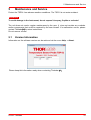
5.1
Version Information
Information on the software version can be retrieved via the menu Help -> About:
Please keep this information ready when contacting Thorlabs
© 2012 Thorlabs
35
.
31
TSP01
6
Appendix
6.1
Technical Data
Internal Combined Sensor
Range
Units
Accuracy
Resolution
Temperature Measurement
Rel. Humidity Measurement
-50 °C to +150 °C
0 % to 100 %RH
°C, K, °F
%RH
±1 °C (0 to 70 °C)
± 2 %RH (20 to 80 %RH)
± 0.6°C (25 °C)
± 3 %RH (0-20 and 80-100 %RH)
0.2 °C
0.4 %
External Sensor, included
Type
EPCOS NTC M861 (R0 = 10 k
@ T0 = 25 °C, B = 3988 K)
Measurement Range
-15 °C to 200 °C
Accuracy
± 0.5 °C (25 °C)
Resolution
0.05 °C
External Sensors
2
Number of channels
Connector
2.5 mm earphone jack
Supported Sensor Type
Units
Measurement Range
NTC
°C, K, °F
200
to 80 k
Interface and Power Supply
Interface
Power Supply
Measurement Update Rate
USB2.0 (Test & Measurement Device)
5 VDC, 20 mA via USB
max. 1/sec
General
Operating Temperature Range 1)
Storage Temperature Range
Dimensions (W x H x D)
Weight
1)
0 - 40 °C
-40 to 70 °C
69.5mm x 20.5mm x 12.0mm
< 50 g (w/o external sensor)
non-condensing
All technical data are valid at (23 ± 5) °C and (45 ± 15) % rel. humidity (non condensing)
32
© 2012 Thorlabs
6 Appendix
6.2
Certifications and Compliances
Category
Standards or description
EC Declaration of
Conformity - EMC
Meets intent of Directive 2004/108/EC 1 for Electromagnetic Compatibility. Compliance was
demonstrated to the following specifications as listed in the Official Journal of the European
Communities:
EN 61326-1:2006
Electrical equipment for measurement, control and laboratory use –
EMC requirements:
Immunity: complies with basic immunity test requirements 2.
Emission: complies with EN 55011 Class B Limits 2,4,
IEC 610003-2 and IEC 61000-3-3.
IEC 61000-4-2
Electrostatic Discharge Immunity (Performance Criterion B)
IEC 61000-4-3
Radiated RF Electromagnetic Field Immunity (Performance Criterion
A)
IEC 61000-4-4
Electrical Fast Transient / Burst Immunity (Performance Criterion B)
IEC 61000-4-6
Conducted RF Immunity (Performance Criterion A)
FCC EMC
Compliance
Emissions comply with the Class B Limits of FCC Code of Federal Regulations 47, Part 15,
Subpart B 2,4.
EC Declaration of
Conformity - Low
Voltage
Compliance was demonstrated to the following specification as listed in the Official Journal
of the European Communities:
Low Voltage Directive 2006/95/EC 7
EN 61010-1:2001
Safety Requirements for Electrical Equipment for Measurement,
Control and Laboratory Use - Part 1: General Requirements
U.S. Nationally
Recognized Testing
Laboratory Listing
UL 61010-1 2nd ed.
Canadian
Certification
CAN/CSA C22.2 No.
61010-1 2nd ed.
Additional
Compliance
IEC 61010-1:2001
Equipment Type
Test and Measuring
Safety Class
Class I equipment (as defined in IEC 60950-1:2001)
ISA-82:02.01 2nd ed.
1
Replaces 89/336/EEC.
2
Compliance demonstrated using high-quality shielded interface cables shorter than or equal to 3 meters.
4
Emissions, which exceed the levels required by these standards, may occur when this equipment is connected to a test object.
7
Replaces 73/23/EEC, amended by 93/68/EEC
© 2012 Thorlabs
33
TSP01
6.3
List of Acronyms
The following acronyms and abbreviations are used in this manual:
GUI
Graphic User Interface
NTC
RH
SCPI
USB
Resistor with Negative Temperature Coefficient (aka Thermistor)
Relative Humidity
Standard Commands for Programmable Instruments
Universal Serial Bus
34
© 2012 Thorlabs
6 Appendix
6.4
Thorlabs Worldwide Contacts
USA, Canada, and South America
Thorlabs, Inc.
56 Sparta Avenue
Newton, NJ 07860
USA
Tel: 973-579-7227
Fax: 973-300-3600
www.thorlabs.com
www.thorlabs.us (West Coast)
Email: [email protected]
Support: [email protected]
Europe
Thorlabs GmbH
Hans-Böckler-Str. 6
85221 Dachau
Germany
Tel: +49-8131-5956-0
Fax: +49-8131-5956-99
www.thorlabs.de
Email: [email protected]
UK and Ireland
Thorlabs Ltd.
1 Saint Thomas Place, Ely
Cambridgeshire CB7 4EX
United Kingdom
Tel: +44-1353-654440
Fax: +44-1353-654444
www.thorlabs.com
Email: [email protected]
Support: [email protected]
France
Thorlabs SAS
109, rue des Côtes
78600 Maisons-Laffitte
France
Tel: +33-970 444 844
Fax: +33-811 38 17 48
www.thorlabs.com
Email: [email protected]
Scandinavia
Thorlabs Sweden AB
Mölndalsvägen 3
412 63 Göteborg
Sweden
Tel: +46-31-733-30-00
Fax: +46-31-703-40-45
www.thorlabs.com
Email: [email protected]
Japan
Thorlabs Japan, Inc.
Higashi Ikebukuro
Q Building 2nd Floor 2-23-2
Toshima-ku, Tokyo 170-0013
Japan
Tel: +81-3-5979-8889
Fax: +81-3-5979-7285
www.thorlabs.jp
Email: [email protected]
China
Thorlabs China
Room A101, No. 100
Lane 2891, South Qilianshan Road
Putuo District
Shanghai 200331
China
Tel: +86-21-60561122
Fax: +86-21-32513480
www.thorlabs.hk
Email: [email protected]
© 2012 Thorlabs
35
TSP01
Thorlabs 'End of Life' Policy (WEEE)
As required by the WEEE (Waste Electrical and Electronic Equipment Directive) of the
European Community and the corresponding national laws, Thorlabs offers all end users
in the EC the possibility to return “end of life” units without incurring disposal charges.
This offer is valid for Thorlabs electrical and electronic equipment
• sold after August 13th 2005
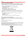
• marked correspondingly with the crossed out “wheelie bin” logo
(see figure below)
• sold to a company or institute within the EC
• currently owned by a company or institute within the EC
• still complete, not disassembled and not contaminated.
As the WEEE directive applies to self contained operational electrical and electronic
products, this “end of life” take back service does not refer to other Thorlabs products,
such as:
• pure OEM products, that means assemblies to be built into a unit by the user
(e. g. OEM laser driver cards)
• components
• mechanics and optics
• left over parts of units disassembled by the user (PCB’s, housings etc.).
Waste treatment on your own responsibility
If you do not return an “end of life” unit to Thorlabs, you must hand it to a company
specialized in waste recovery. Do not dispose of the unit in a litter bin or at a public waste
disposal site.
WEEE Number (Germany) : DE97581288
Ecological background
It is well known that waste treatment pollutes the environment by releasing toxic products
during decomposition. The aim of the European RoHS Directive is to reduce the content
of toxic substances in electronic products in the future.
The intent of the WEEE Directive is to enforce the recycling of WEEE. A controlled
recycling of end-of-life products will thereby avoid negative impacts on the environment.
Crossed out "Wheelie Bin" symbol
36
© 2012 Thorlabs
6 Appendix
Warranty
Thorlabs warrants material and production of the TSP01 for a period of 24 months starting with
the date of shipment. During this warranty period Thorlabs will see to defaults by repair or by
exchange if these are entitled to warranty.
For warranty repairs or service the unit must be sent back to Thorlabs. The customer will carry
the shipping costs to Thorlabs, in case of warranty repairs Thorlabs will carry the shipping costs
back to the customer.
If no warranty repair is applicable the customer also has to carry the costs for back shipment.
In case of shipment from outside EU duties, taxes etc. which should arise have to be carried by
the customer.
Thorlabs warrants the hard- and software determined by Thorlabs for this unit to operate
fault-free provided that they are handled according to our requirements. However, Thorlabs
does not warrant a fault free and uninterrupted operation of the unit, of the software or firmware
for special applications nor this instruction manual to be error free. Thorlabs is not liable for
consequential damages.
Restiction of Warranty
The warranty mentioned before does not cover errors and defects being the result of improper
treatment, software or interface not supplied by us, modification, misuse or operation outside
the defined ambient stated by us or unauthorized maintenance.
Further claims will not be consented to and will not be acknowledged. Thorlabs does explicitly
not warrant the usability or the economical use for certain cases of application.
Thorlabs reserves the right to change this instruction manual or the technical data of the
described unit at any time.
© 2012 Thorlabs
37
TSP01
Copyright
Thorlabs GmbH has taken every possible care in preparing this Operation Manual. We however
assume no liability for the content, completeness or quality of the information contained therein.
The content of this manual is regularly updated and adapted to reflect the current status of the
software. We furthermore do not guarantee that this product will function without errors, even if
the stated specifications are adhered to.
Under no circumstances can we guarantee that a particular objective can be achieved with the
purchase of this product.
Insofar as permitted under statutory regulations, we assume no liability for direct damage,
indirect damage or damages suffered by third parties resulting from the purchase of this
product. In no event shall any liability exceed the purchase price of the product.
Please note that the content of this User Manual is neither part of any previous or existing
agreement, promise, representation or legal relationship, nor an alteration or amendment
thereof. All obligations of Thorlabs GmbH result from the respective contract of sale, which also
includes the complete and exclusively applicable warranty regulations. These contractual
warranty regulations are neither extended nor limited by the information contained in this User
Manual. Should you require further information on this product, or encounter specific problems
that are not discussed in sufficient detail in the User Manual, please contact your local Thorlabs
dealer or system installer.
All rights reserved. This manual may not be reproduced, transmitted or translated to another
language, either as a whole or in parts, without the prior written permission of Thorlabs GmbH.
Status: 2012
Copyright © Thorlabs GmbH. All rights reserved.
38
© 2012 Thorlabs