1
ProSeries
TM
by Blue-White
Industries,
Ltd.
Industries,Ind.
Ltd.
TM
SONIC-PRO Ultrasonic Flow Meters
Engineering and Technical Data
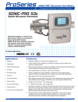
SONIC-PRO
S3c
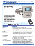
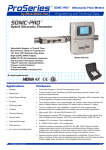
Hybrid Ultrasonic Flowmeter
Selectable Doppler or Transit Time
Non-Invasive clamp on transducers
High quality QVGA display
NEMA 4X (IP 66) washdown enclosure
Full function front panel interface
“Smart” external communications
Process control features
2 Year warranty
Liquid applications
NEMA 4X
Applications:
Features:
!
Sewage
!
Selectable Doppler or Transit Time operating mode.
!
Wastewater
!
Custom quality metric algorithms and DSP technology ensures reliable, high
accuracy measurements.
!
Pulp & Paper Slurries
!
!
Quick and easy clamp-on transducer installation. Proprietary AGC (Automatic Gain
Control) algorithm eliminates manual gain adjustment.
DI water
!
User programmable via 5-button, menu driven interface.
!
Discharge water
!
!
Factory configured for easy installation. Includes five user programmable,
password protected configurations for multiple user and portable applications.
Caustics
!
High quality 320 x 240 pixel QVGA backlit LCD.
!
Chemical Slurries
!
!
Data logging to standard SD Card format. User configurable to time interval, flow
rate and total set-point triggers. 500,000 events with included 32MB SD Card.
Ground water
!
Isolated 4-20 mA output - fully configurable.
!
Food and Beverage
!
0 - 1000Hz Pulse output - fully configurable.
!
Petrochemical
!
!
Any sound conducting liquid
Computer connection via RS-232, RS-485, USB, Ethernet. Permits remote access
and control of all functions including real-time display, system configuration, data
logging, remote data capture and process control functions. Software permits
remote internet access through local network set-up.
!
Process control via three independently configurable 10 amp, form C relays.
Configure to flow rate for high/low/range rate alarm or to flow total for either
manual trigger batch operations or flow triggered batch operations.
TDS #85000-077 rev.09182007
1 of 4
SONIC-PRO
Ultrasonic Flow Meters
Engineering and Technical Data
Installation:
Fluid Requirements
The Sonic-Pro series Hybrid Ultrasonic Flow Meters can measure fluid flow in virtually any fluid in which sound waves can travel. The Sonic-Pro
meters are considered “hybrid” because they can measure fluid flow using either the Doppler or Transit Time methods. The Sonic-Pro ultrasonic sound
transducers are clamped to the outside of the pipe wall and include no moving parts. This method of flow measurement is safe, non-intrusive and very easy
to service.
The Doppler measurement method requires particles be present in the flow stream to “reflect” the sound waves. The meter may be operated in the
Doppler mode when the fluid contains 0.02% to 15% (200 to 150,000 ppm) of particles .
The Transit Time measuring method requires relatively “clean” fluid to enable the sound waves to complete their circuit. The meter may be operated in
the Transit-Time mode when the fluid contains 0% to 1% (0 to 10,000 ppm) of particles. To allow for changes in the fluid’s particle count, the Sonic-Pro
monitors the signal gain and employs an Automatic Gain Control (AGC) algorithm that periodically adjusts the gain maintain the optimum power level.
The speed at which sound travels in the fluid must be known. The factory will configure the meter for a known fluid during the initial configuration. The
Sonic-Pro model S3c includes a 5-button user interface and remote PC software that can be used to configure the meter. Many common fluids are listed
in the software and can be selected directly from the menu. Provided the speed of sound in the fluid is known, custom “unknown” fluids can be input
manually by the user. A list of various fluids and their sound speeds are provided in the user manual.
Flow Stream Requirements
To ensure measurement accuracy requires a fully developed turbulent flow profile. Pulsating, swirling and other disruptions in the flow stream will
affect accuracy. Flow conditions with a Reynolds Number greater than 4000 will demonstrate fully developed turbulent flow. A Reynolds Number less
than 2000 indicates laminar flow and may result in inaccurate readings.
REYNOLDS NUMBER EQUATION:
REYNOLDS NUMBER =
Fully Developed
Turbulent Flow
3160 x Q x G
D x V
Disturbed Flow
(due to swirling)
Laminar
Flow
Where:
Flow rate of the fluid in GPM = Q
Specific gravity of the fluid
=G
Pipe inside diameter in inches = D
Fluid viscosity in centepoise = V
Flow Velocity Profile
Pipe Cross Section
Minimum Straight Pipe Length Requirements
The meter’s accuracy is affected by disturbances such as pumps, elbows, tees, valves, etc., in the flow stream. Install the meter in a straight run of
pipe as far as possible from any disturbances. The distance required for accuracy will depend on the type of disturbance.
Type Of Disturbance
Minimum Inlet Pipe Length
Flange - Reducer - 90o Elbow
10 X Pipe Inside Diameter
5 X Pipe Inside Diameter
Two 90 Elbows -1 plane
15 X Pipe Inside Diameter
5 X Pipe Inside Diameter
Two 90o Elbows -2 planes
20 X Pipe Inside Diameter
5 X Pipe Inside Diameter
Pump Or Gate Valves
25 X Pipe Inside Diameter
5 X Pipe Inside Diameter
o
Minimum Outlet Pipe Length
Transducer Mounting Location
!
!
!
!
!
!
The meter can be mounted on horizontal or vertical runs of pipe.
Mounting on the sides (3 o'clock and 9 o’clock) position on horizontal pipe is recommended.
Mounting anywhere around the diameter of vertical pipe is acceptable, however, the pipe must be completely full of fluid at all times.
Back pressure is required on downward flows to ensure a full pipe.
See the minimum straight length of pipe requirement chart above.
The meter can accurately measure flow from either direction.
NO
NO
Air could be trapped
Pipe must be full
OK
Air bubble
NO
OK
Down flows
must have
back pressure
!
OK
Lm
10D L m
5D
See minimum straight length requirements above
2 of 4
OK
NO
Sediment
TDS #85000-077 rev.09182007
SONIC-PROTM Ultrasonic Flow Meters
Engineering and Technical Data
Specifications:
General Operation________________________
Display
Hybrid. User-selectable Doppler or Transit Time operating modes.
320 x 240 pixel QVGA backlit LCD, UV resistant.
Simultaneous Rate and Total: 10 digit maximum + exponent to E+32
Decimal location configurable to 10 places.
Fluid Types
Display Languages
Virtually any acoustically conductive fluid.
Transit time mode operation from 0% to 1% (0 to 10,000 ppm) particulate.
Doppler mode operation from 0.02% to 15% (200 to 150,000 ppm) of 100
micron particulate.
English, Spanish, French or German selectable.
Nominal Pipe Sizes
Security
Measuring Principle
0.5 inch - 12.0 inch (20mm to 315mm)
Display Volume Units
Most metal and plastic pipes
Independently configurable Rate and Total display units in: U.S. Gallons,
ounces, barrels (US liquid), barrels (US oil), cubic feet, acre feet, Imperial
(British) gallons, liter, cubic meter, or user defined “custom” units.
Pipe Liner Materials
Most plastic liners
Display Time Units
Fluid Velocity Range
Seconds, minutes, hours, days. Independent Rate and Total display units.
0 to 30 f/s (0 to 9 m/s)
Display/Output Update Time
Accuracy
5.0 Seconds
(default setting)
1.0 Seconds
0.5 Seconds
Five-button positive action tactile switch keypad.
Programmable master password and individual configuration passwords.
Pipe Materials
Flow Rate
Averaging Time
Keypad
Selectable: 0.25, 0.50, 1.0 (default), 2.5, 5.0 seconds.
Accuracy at Pipe Inside Diameter
Doppler all pipe sizes
Transit Time ½” to 1”
Transit Time 1-1/4” to 12”
+/-1% of rate > 8 ft/sec
+/-0.06 ft/sec < 8 ft/sec
+/-1% of rate > 1 ft/sec
+/-0.01 ft/sec < 1 ft/sec
+/-1% of rate > 12 ft/sec
+/-0.12 ft/sec < 12 ft/sec
+/-2% of rate > 12 ft/sec
+/-0.25 ft/sec < 12 ft/sec
+/-1% of rate > 5 ft/sec
+/-0.05 ft/sec < 5 ft/sec
+/-2% of rate > 12 ft/sec
+/-0.25 ft/sec < 12 ft/sec
Electronics _______________________________
Enclosure
NEMA 4X (IP66), Powder coated aluminum, stainless steel mounting
plates, clamps and hardware.
Dimensions: 11.00H x 8.60W x 5.00D inches (279H x 218W x 127D mm)
Weight 6.8 lb. (3.1 Kg.)
Mounting
Wall, pipe (vertical or horizontal) or panel mounting. Hardware included.
Panel opening: 10.63H x 8.10W inches ( 270H x 206W mm)
Panel Depth. Rear: 2.78 inches (71 mm), Front : 2.18 inches (55 mm)
Power Requirements
90-264 VAC 50/60Hz or 15-30 VDC
Power Consumption
Flow Rate Display Averaging
Selectable: 0.50, 1.0, 2.5, 5.0 (default), 10.0 seconds.
Data Outputs
! Isolated 4-20 mA output - fully configurable, invertible
! 0-1000 Hz Pulse output - fully configurable, invertible
Data Logging
Date/time stamped flow rate and total data in FAT32 file format, easily
imported into Excel. Configurable to trigger on time interval (1-999,999
sec), rate and/or total set-point values. Over 500,000 log events possible
with included 32MB SD Card.
Process Control
Three independently configurable 10 amp Form C, NO/NC relays.
!
Configure to flow rate for high/low/range rate alarm. Programmable
release values enable auto release or manual latching operation.
!
Configure to flow total for manual trigger batch operations or
automatically triggered, timed batch operations.
External Communications
Computer connection via RS-232, RS485, USB, Ethernet.
! Includes user communication and complete configuration software
! Permits remote internet access through local network set-up
! Remotely access and upload data logging files.
Clamp-On Transducers___________________
40 watts maximum
Housing
Operating Temperature
NEMA 4X (IP66), Powder coated aluminum, stainless steel mounting
clamps and hardware.
Dimensions: 3.12H x 2.95W x 1.60D inches (79H x 75W x 41D mm)
Weight: 0.8 lb. (0.4 kg.) each
14OF to 140OF (-10OC to 60OC)
Storage Temperature
-40OF to 158OF (-40OC to 70OC)
Cable
Shielded coaxial RG/U Type:59. PVC jacket, black. RoHS Compliant.
Standard length: 10 ft. (3m)
Optional lengths available: 25 ft. (7m), 50 ft. (15m), 100 ft. (30m)
Nominal Pipe Sizes
A series transducer: 0.5 inch - 2.0 inch (20mm to 63mm)
B series transducer: 2.0 inch - 12.0 inch (63mm to 300mm)
Pipe Surface Temperature
14OF to 212OF (-10OC to 100OC)
TDS #85000-077 rev.09182007
3 of 4
SONIC-PRO
Ultrasonic Flow Meters
Engineering and Technical Data
Dimensions:
5.000 in
127 mm
8.600 in
218 mm
9.225 in
234 mm
.750 in
19 mm
S3 Series | Hybrid Ultrasonic Flowmeter
NEMA 4X
IP 66
.900 in
23 mm
S3 Series | Hybrid Ultrasonic Flowmeter
NEMA 4X
IP 66
10.38 in
264 mm
11.70 in
297 mm
1.513 in
38 mm
ProSeries
TM
Doppler /
Transit Time
by Blue-White
Industries, Ind.
Ltd.
1.288 in
33 mm
.800 in
20 mm
TYP.
10.38 in
264 mm
Doppler /
Transit Time
ProSeries
TM
by Blue-White
Industries, Ind.
Ltd.
2.500 in
63,5 mm
7.826 in
199 mm
11.00 in
279 mm
3.12 in
79 mm
1.60 in
41 mm
2.95 in
75 mm
TRANSDUCER (Series A and B)
With Wall Mount Hardware
Model Number Matrix:
Sonic-Pro Part Number Matrix
Pipe Size
Base Electronics Package
S1 Factory configured without display
S2 Factory configured with display
S3 Factory configured with user configurable display
Smart Communications
C Ethernet, USB, RS-232, RS-485 with PC software
X None
Power Supply Cord
1 U.S. 115V with NEMA 5/15 plug
2 European 220V with CEE 7/VII plug
3 U.S. 230V with NEMA 6/15 plug
Transducer
A1
A3
B1
B3
Small pipe <= 2" diameter with 10 ft cable
Small pipe <= 2" diameter with 50 ft cable
Large pipe >= 2" diameter with 10 ft cable
Large pipe >= 2" diameter with 50 ft cable
Nominal Pipe Size
Select from options list
Pipe Pressure Rating
Select from options list
Pipe Material
Select from options list
Display V olume Units
G
L
F
A
M
Gallons
Liters
Cubic Feet
Acre Feet
Cubic Meters
Display Tim e Units
M Minutes
H Hours
D Days
Fluid
005
007
010
012
015
020
025
030
040
050
060
080
100
120
020
025
032
040
050
063
075
090
110
125
140
160
180
200
225
250
280
312
XXX
1/2"
3/4"
1"
1-1/4"
1-1/2"
2"
2-1/2"
3"
4"
5"
6"
8"
10"
12"
20mm
25mm
32mm
40mm
50mm
63mm
75mm
90mm
110mm
125mm
140mm
Pipe Pressure Rating
SA
SB
SC
SD
SE
SF
SG
SH
SI
SJ
DA
DB
DC
DD
PA
PB
PC
PD
PE
BB
BC
BD
BE
B7
XX
Sch 10 (ASTM D 1785)
Sch 20 (ASTM D 1785)
Sch 30 (ASTM D 1785)
Sch 40 (ASTM D 1785)
Sch 60 (ASTM D 1785)
Sch 80 (ASTM D 1785)
Sch 100 (ASTM D 1785)
Sch 120 (ASTM D 1785)
Sch 140 (ASTM D 1785)
Sch 160 (ASTM D 1785)
SDR 41 (ASTM D 2241)
SDR 26 (ASTM D 2241)
SDR 21 (ASTM D 2241)
SDR 13.5 (ASTM D 2241)
PN 4 Metric (DIN 8062)
PN 6 Metric (DIN 8062)
PN 10 Metric (DIN 8062)
PN 16 Metric (DIN 8062)
PN 20 Metric (DIN 8062)
CLASS B British (BS 3506)
CLASS C British (BS 3506)
CLASS D British (BS 3506)
CLASS E British (BS 3506)
CLASS 7 British (BS 3506)
User configured
160mm
180mm
200mm
225mm
250mm
280mm
312mm
USER
Select from options list
Display language
E
S
G
F
S3
C
1
A1
015
SD
J
G M
AL
E
R
Industries, Ltd.
4 of 4
Brass (Naval)
Copper
FRP (fiberglass reinforced plastic)
Iron (cast)
Iron (ductile)
Nylon
Polyethylene (HDPE)
Polyethylene(LDPE)
Polypropylene
PVC / CPVC
PVDF
Stainless Steel 304
Stainless Steel 304L
Stainless Steel 316
Steel (1% Carbon, hardened)
Steel (carbon)
Titanium
User configured
AA
AB
AC
AD
AE
AF
AG
AH
AI
AJ
AK
AL
AM
AN
XX
Alcohol (Ethyl alcohol; Ethanol)
Benzene
Ethylene glycol
Ethylene glycol / water (50%)
Gasoline
Isopropyl alcohol
Methyl alcohol (Methanol)
Methyl ethyl Ketone
Milk, homogenized
Oil, diesel
Toluene
W ater (distilled; waste)
W ater, heavy
W ater, sea
User configured
Fluid
English
Spanish
German
French
Sample model number
TDS #85000-xxx 05192007
Blue-White
Pipe Material
A
B
C
D
E
F
G
H
I
J
K
L
M
N
O
P
Q
X
5300 Business Drive, Huntington Beach, CA 92649
Tel: 714-893-8529 Fax: 714-894-9492
www.blue-white.com Email: [email protected]
Note: Other options available.
3 of 4
All trademarks are the property of their respective owners.
TDS #85000-077 rev.09182007