1
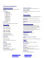
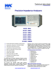
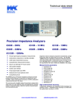
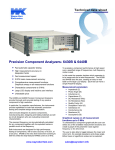
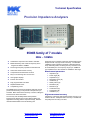
Technical Specification Precision Impedance Analyzers 6500B family of 7 models 20Hz – 120MHz Characterize components from 20Hz to 120 MHz Models defined by their maximum frequency which ranges from 5MHz to 120MHz Precise high frequency impedance measurements 0.05 % basic measurement accuracy Comprehensive measurement functions Easy to use with large TFT touch screen Clear graphic displays Intuitive user interface Fully programmable over GPIB Replaces 6500A series Competitively priced The 6500B series of Precision Impedance Analyzers provide precise and fast testing of components at frequencies up to 120 MHz. Basic measurement accuracy is ±0.05% making the instruments the best in their class. The accuracy and versatility makes these precision instruments the ideal choice for many different tasks and applications including passive component design, dielectric material characterisation and m anufacturing test. Engineers need to evaluate component characteristics at high frequencies with very high levels of accuracy. The 65120B 120MHz Precision Impedance Analyzer is therefore ideal for many demanding tasks, combining accuracy and ease of use at an affordable price. If a frequency range up to 120MHz is not required then the other models are available in this range. Measurement parameters Impedance (Z) Phase Angle (Ø) Capacitance (C) Dissipation Factor (D) Inductance (L) Quality Factor (Q) Resistance (R) Reactance (X) Conductance (G) Susceptance (B) Admittance (Y) High measurement accuracy Capacitance, inductance and impedance basic accuracy is an excellent ±0.05%. Dissipation factor accuracy is ±0.0005 and the quality factor accuracy is ±0.05%. www.waynekerrtest.com [email protected] www.waynekerr.de [email protected] Graphical sweep of components The 6500B series of Precision Impedance Analyzer are highly accurate high frequency component analyzers with a host of useful features. Graphical sweep of two measured parameters is available and displayed on the large clear colour display. Swept parameters are frequency, drive level and DC bias. Display formats available include series or parallel equivalent circuit. For single frequency measurements a meter mode is available. Variable drive and bias levels AC drive levels up to 1V or 20mA can be selected to evaluate components in realistic operating environments. /D1 DC bias option provides 0 to +40V dc bias voltage and 0 to +100mA dc bias current. /D2 option provides -40V to +40V dc bias voltage. Printer outputs Hard copy printouts can be obtained in a number of ways including direct to an HP-PCL compatible graphics printer or Epson compatible text/ticket printer. A networked HP-PCL compatible printer may also be used via the Ethernet connection. Component connections Four front panel BNC connectors permit three or four terminal connections with the screens at ground potential. The 1J1011 Component Fixture, supplied as standard, ensures optimum performance when measuring a wide range of leaded components and devices. 1J1012 (2 terminal) and 1J1014 (4 terminal) SMD Fixtures allow connection to surface mount devices. Protection against charged capacitors External control High precision measuring instruments can be damaged by charged capacitors which can cause costly repairs and unacceptable downtime. All the models in the range incorporate protection against charged capacitors. The GPIB interface is used to control the instrument and read back measured values for applications such as quality control or for archiving purposes. Comprehensive and precise component tests at higher frequencies An Ethernet interface* similarly allows the instrument to be controlled and to send out data - allowing it to be integrated into many test environments. The 6500 series is best summarised by “Comprehensive and precise component tests at higher frequencies”. The instrument is the perfect solution for those who have demanding component measurement needs. Wide range of interfaces An external monitor or projector may be connected to the instrument. The ability to provide a large screen display of measurement results is invaluable in production environments or for teaching and training. Instrument control from both a keyboard and mouse is available. Any keyboard or mouse, with either a PS/2 or USB interface, can simply be connected to provide an alternative method of instrument control and operation. Data storage and retrieval All measurement and setup data can be stored using the Ethernet interface* or a USB flash memory (supplied as standard). Setup Data Up to 20 instrument setups may be locally stored for each mode. Bin handling option /B1 option (non-isolated 5V) or /B2 option (isolated 24V) signals are available through a 25-way D-type connector. 10 bins can be set using absolute or percentage limits. Simultaneous plot of impedance and phase displayed against frequency on a clear colour display * Future Enhancement www.waynekerrtest.com [email protected] www.waynekerr.de [email protected] Technical specifications Measurement parameters Any of the following parameters can be measured and displayed: AC functions Impedance (Z) Phase Angle (Ø) Capacitance (C) Dissipation Factor (D) Inductance (L) Quality Factor (Q) Resistance (R) Reactance (X) Conductance (G) Susceptance (B) Admittance (Y) Graphical sweep mode Allows graphical sweep of any two measurement parameters Swept parameters: - frequency, drive level or DC bias Meter mode Allows the instrument to be used as a standard LCR meter Setup Data Series or parallel equivalent circuit – all parameters Test conditions 6510B 6515B 20Hz to 10MHz 20Hz to 15MHz 6520B 6530B 6550B 20Hz to 20MHz 20Hz to 30MHz 20Hz to 50MHz Up to 20 instrument setups may be locally stored for each mode. Measurement connections Four front panel BNC connectors permit three or four terminal connections with the screens at ground potential. Frequency range 20Hz to 5MHz Option /B2 (isolated) Common 24V input. Outputs 0 to 24V with >10mA current source capability. Mode of operation Display format 6505B Option /B1 (non-isolated) Common 0V. Bin outputs 0 to 5V(nominal) with >10mA current sink capability. 1J1011 Component Fixture (supplied as standard) allows connection to leaded components and devices. 1J1012 (2 terminal) and 1J1014 (4 terminal) Fixtures allow connection to surface mount devices. Measurement accuracy 65120B 20Hz to 120MHz Frequency step size: 0.1mHz Accuracy of set frequency ±0.005% Dissipation factor ±0.0005 (1+D2)* Quality factor ±0.05 %( Q+1/Q)* AC drive level Capacitance / Inductance / Impedance 10mV to 1Vrms* 200µA to 20mArms* ±0.05%* *Varies with frequency, drive level and measured impedance *Varies with frequency Signal source impedance: 50 Ohm nominal General Power Supply DC bias Input voltage 90VAC to 264VAC (Autoranging) Option /D1 Mains frequency 0 to +100mA dc bias current 0 to +40V dc bias voltage 47Hz to 63Hz Display Option /D2 8.4″VGA (640 x 480) colour TFT with touch panel -40V to +40V dc bias voltage Local Printer Binning (optional) 10 bins with absolute and percentage limits. 25 way D-type interface connector. HP-PCL compatible graphics printing Centronics / parallel printer port, Epson compatible text / ticket printing Network Printer HP-PCL compatible graphics printing www.waynekerrtest.com [email protected] www.waynekerr.de [email protected] GPIB interface Installation category External instrument control. 24 pin IEEE 488 connector II in accordance with IEC664 Remote trigger Pollution degree Rear panel BNC with internal pull-up, operates on logic low or contact closure 2 - mainly non-conductive USB interface Complies with the requirements of EN61010-1 Safety Two Universal Serial Bus Interfaces USB 1.1 compliant EMC Complies with EN61326 for emissions and immunity VGA interface Mechanical 15-way D-type connector to drive an external monitor in addition to the instrument display Height 190 mm (7.5″ ) Width 440 mm (17.37″ ) Depth 525 mm (20.5″ ) Weight 14.5 kg (32 lb) Network interface 1 10/100-BASE-TX Ethernet controller. RJ45 connector Keyboard interface Order codes Description Standard USB or PS/2 keyboard port. Instrument front panel remains active with keyboard plugged in Order code 6505B 1J6505B 5MHz Precision Impedance Analyzer 6510B 1J6510B 10MHz Precision Impedance Analyzer 6515B 1J6515B 15MHz Precision Impedance Analyzer 6520B 1J6520B 20MHz Precision Impedance Analyzer 6530B 1J6530B 30MHz Precision Impedance Analyzer Mouse interface Standard USB or PS/2 mouse port. Touch screen remains enabled when the mouse is connected. Bin handler (option) /B1 option (non-isolated 5V) or /B2 option (Isolated 24V). 25-way D-type connector Environmental conditions This equipment is intended for indoor use only in a nonexplosive and non-corrosive atmosphere 6550B 1J6550B 50MHz Precision Impedance Analyzer 65120B 1J65120B 120MHz Precision Impedance Analyzer with either /D1 or /D2 option as standard Temperature range Storage -20°C to 60°C Operating 0°C to 40°C Full Accuracy 18°C to 28°C Up to 80% non-condensing All models supplied with:User manual 2m AC power cable Universal component fixture (1J1011) USB memory Altitude Options Relative humidity Up to 2000 m ¹ Future enhancement Description Order code Bin handler (non-isolated) Bin handler (isolated 24V) DC Bias (0 to 40V, 0 to 100mA) DC Bias (-40V to +40V) /B1 /B2 /D1 /D2 UK EUROPE Wayne Kerr Electronics Vinnetrow Business Park Vinnetrow Road, Runcton Chichester, West Sussex PO20 1QH, UK Tel: +44 1243 792200 Fax: +44 1243 792201 Wayne Kerr Europe GMBH Märkische Str. 38-40 58675 Hemer Germany Tel: +49 2372 557870 Fax: +49 2372 5578790 Please consult our website for details of our other companies and distributors around the world. . www.waynekerrtest.com [email protected] November 2007 Issue A4 Wayne Kerr’s policy is one of continuous development and consequently the product may vary in detail from the description and specification in this publication