1
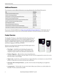
ALARM MONITORING & CONTROL SYSTEM
TBox20 USER’S MANUAL
TBox20 user‘s manual
Legal notice:
All rights reserved. Reproduction, transfer, distribution or storage of part or all of the contents in
this document in any form without the prior written permission of Teltonika is prohibited.
Other product and company names mentioned herein may be trademarks or trade names of their
respective owners. Copyright © 2008 UAB „Teltonika“.
Disclaimer:
The use of Alarm Monitoring and Control System TBox20 is at sole discretion of the user.
Teltonika cannot be held responsible for any damages arising due to use of Alarm Monitoring and
Control System TBox20. Therefore any liability claims would be discarded.
2
TBox20 user‘s manual
CONTENT
1.
2.
3.
INTRODUCTION ....................................................................................................................... 4
TECHNICAL SPECIFICATION ................................................................................................ 4
MECHANICAL INTEGRATION .............................................................................................. 4
3.1.
PACKAGE CONTENTS .................................................................................................... 4
3.2.
DIMENSIONS .................................................................................................................... 4
3.3.
FRONT PANEL .................................................................................................................. 5
4. CONNECTORS PIN_OUT......................................................................................................... 6
4.1.
CONNECTORS FRONT UP PIN-OUT ............................................................................. 6
4.2.
CONNECTORS FRONT DOWN PIN-OUT ...................................................................... 6
4.4.
SAMPLE ELECTRICAL CONNECTION ......................................................................... 7
5. INSTALATION AND STARTING ............................................................................................ 8
5.1.
INSTALLING A SIM CARD ............................................................................................. 8
5.2.
DIP SWITCH SETTINGS .................................................................................................. 9
5.3.
CONNECTION TO PC ....................................................................................................... 9
6. DATA CONFIGURATION ...................................................................................................... 10
6.1.
APPLICATION‘S LOGICAL ELEMENT ....................................................................... 10
6.2.
FUNCTIONS..................................................................................................................... 11
6.3.
LOGICS............................................................................................................................. 11
6.4.
EVENTS............................................................................................................................ 12
6.5.
ACTIONS.......................................................................................................................... 14
6.6.
USERS............................................................................................................................... 16
6.7.
SETTINGS ........................................................................................................................ 17
6.8.
TEST.................................................................................................................................. 18
6.9.
STATUS ............................................................................................................................ 19
6.10.
LOG ............................................................................................................................... 19
7. SUPPORT.................................................................................................................................. 20
3
TBox20 user‘s manual
1. INTRODUCTION
TBox20 is a compact monitoring and control device for remote objects with support for
Short Messages (SMS). The device is configurable through internal WEB server interface via
GSM network and RS232 interface. Multiple users can interrogate TBox20 or be notified on
configurable events.
2. TECHNICAL SPECIFICATION
•
•
•
•
•
•
•
•
•
•
•
•
Power 24V ±10% (for the model TBox20-2401)
Wireless modem: Quad Band GSM (850/900/1800/1900MHz)
4 digital inputs (“0” (false) 0 – 1V, “1” (true) 2-24V, terminal blocks)
2 analog inputs. (0 – 10V max 15V, 0-20mA max 30ma, terminal blocks)
4 relay outputs (~250V, 7A, terminal blocks)
Interfaces RS232 (RJ45 connector) and GSM GPRS (antenna MMCX connector)
Alarm message service via SMS, E-Mail
Protocols HTTP and SMTP
Configurable through internal WEB server interface
Watchdog controller
Operating temperature range from -20°C to +55°C
DIN Rail Mounting
3. MECHANICAL INTEGRATION
3.1. PACKAGE CONTENTS
3.1.1. TBox20;
3.1.2. Serial cable PORT1 (one connector – female COM port, another – RJ45);
3.1.3. GSM antenna (MMCX connector);
3.1.4. The CD with Software and User’s Manual.
3.2. DIMENSIONS
The plastic case of TBox20 is light and suitable for fitting with electronic instruments that can
hook to the DIN EN 50022.
When a place for TBox20 is being planned, it should be considered that GSM antenna, which is
supplied in your package, should NOT be placed in metal case. The supplied antenna usually has
2,5 meters length cable, so if you plan to mount TBox20 into a metal case, please mount the
antenna outside the metal case. If cable length of 2,5 meters is not enough, contact our sales
department to order antennas with longer cables.
4
TBox20 user‘s manual
Picture 3.2.1
3.3. FRONT PANEL
Picture 3.2.2
Device
state LED
4 digital inputs LED
2 serial port
state LED
Serial port connector
Picture 3.3.1
4 relay outputs state LED
PWR – Power LED turns on when power is applied to Tbox20. It also shows the device’s working
status:
• LED ON;
• LED blink low (0.2s ON, 0.6s OFF) – the device is registered in GSM network;
• LED blink high (0.4s ON, 0.4s OFF) – the device transmits via GSM network.
ERR – Error LED turns on when the device has faulty working conditions.
RX – Indicate the receiving data to the device via serial port.
TX – Indicate the sending data from the device via serial port.
DIN – Indicate the digital input’s voltage “true” level.
ROUT – Indicate the relay output status.
RS232 – Standard serial communication port.
5
TBox20 user‘s manual
4. CONNECTORS PIN_OUT
4.1. CONNECTORS FRONT UP PIN-OUT
Picture 4.1.1
Pin name
AIN 1 AIN 1 +
AIN 1 AIN 1 +
DIN 1
DIN 2
DIN 3
DIN 4
┴
+24V
0V
PE
Description
Analog input 1. Input voltage range is from 0 to 10V (max 15V) or input current
range is 0-20mA (max 30mA).
Analog input 2. Input voltage range is from 0 to 10V (max 15V) or input current
range is 0-20mA (max 30mA).
Digital input 1. This input is optically isolated by two different voltage levels: 0…1V
– false; 2…24V – true.
Digital input 2. This input is optically isolated by two different voltage levels: 0…1V
– false; 2…24V – true.
Digital input 3. This input is optically isolated by two different voltage levels: 0…1V
– false; 2…24V – true.
Digital input 4. This input is optically isolated by two different voltage levels: 0…1V
– false; 2…24V – true.
Digital input ground. It is separated from module ground (power supply,
analog input) because digital inputs are optically isolated.
Device power. Voltage is 24V ±10% DC. Power consumption:
Stand by mode ~50mA@24V, peak up to 300mA@24V. As switched power
regulator is used inside, the smaller the voltage, the bigger the current and
vice versa (power consumption remains about the same)
Protection earth.
Table 4.1.1. Connector pin-out
4.2. CONNECTORS FRONT DOWN PIN-OUT
Picture 4.2.1
ROUT 1 NO
ROUT 1 CO
ROUT 1 NC
ROUT 2 NO
ROUT 2 CO
ROUT 2 NC
Relay 1 normally open output.
Relay 1 common output.
Relay 1 normally closed output.
Relay 2 normally open output.
Relay 2 common output.
Relay 2 normally closed output.
Max load ~250V, 7A.
Max load ~250V, 7A.
6
TBox20 user‘s manual
ROUT 3 NO
ROUT 3 CO
ROUT 3 NC
ROUT 4 NO
ROUT 4 CO
ROUT 4 NC
Relay 3 normally open output.
Relay 3 common output.
Relay 3 normally closed output.
Relay 4 normally open output.
Relay 4 common output.
Relay 4 normally closed output.
Max load ~250V, 7A.
Max load ~250V, 7A.
Table 4.2.1. Connector pin-out
4.3. SERIAL PORT (RS232 INTERFACE)
Serial port is used for communication with internal WEB server. Internal WEB server allows to edit
configured data.
Serial port parameters:
• Interface format RS232C
• Logic levels (RS232C levels)
• Speed: 115200 bauds
• Format: 8 bits
• Parity: none
• Stop bits: 1
• Flow control: hardware
Picture 4.3.1. RJ45 connector
The communication connector is an eight way RJ45 PLUG style connector.
RJ45 Pin number
1
2
3
4
5
6
7
8
Description
DSR
DCD
DTR
GND
RXD
TXD
CTS
RTS
Direction
Output
Output
Input
Input
Output
Output
Input
Table 4.3.1. RS232 Connector pin-out
4.4. SAMPLE ELECTRICAL CONNECTION
7
TBox20 user‘s manual
Picture 4.4.1. Sample scheme
5. INSTALATION AND STARTING
5.1. INSTALLING A SIM CARD
•
•
•
•
•
Picture 5.1.1
Picture 5.1.2
•
•
Remove the cover with screwdriver (see the picture
5.1.1).
Slide the SIM card holder toward its hinge to unlock it
(see the picture 5.1.2).
Lift the SIM card holder.
Remove your SIM card from the package (your SIM
card might be inserted already.)
Insert the SIM card into the holder so that the notches
align (see the picture 5.1.3).
Close the SIM card holder.
Slide the SIM card holder away from its hinges to lock it
(see the picture 5.1.4).
Picture 5.1.3
Picture 5.1.4
8
TBox20 user‘s manual
5.2. DIP SWITCH SETTINGS
Dip switch should be set according the picture 5.2.1 for the normal working conditions.
Picture 5.2.1
Switch number
1
OFF
Serial port works in the normal mode
2
3
4
Normal working conditions
Normal working conditions
“Watchdog” off
ON
Serial port works in the “AT
Command” mode
Preset factory parameters
Reset GSM module
“Watchdog” on
Table 5.2.1
5.3. CONNECTION TO PC
5.3.1. Install Tbox20 for windows. To
perform the installation, run the
following programs from your CD or
download folder Tbox20.exe.
5.3.2. Connect PC serial port to the Tbox20
serial port cable PORT1.
5.3.3. After installation you can run the
program by clicking SERVER in
Start/Programs/
Teltonika/Tbox20
directory. To open the program, click the
icon on the taskbar.
5.3.4. Select serial port number to which
Tbox20 is connected.
5.3.5. Write to TCP/IP Port number “5000”.
5.3.6. Click the link http://localhost:5000 and
Internet explorer window will run automatically. There you will see Tbox20
application.
5.3.7. You can find possible port to which is connected TBox20 device by pressing the
button Autodetect. After you need to select detected COM port with record Box.
Sign - (Com2-) – port 2 not exist. Sign + (Com4 Box+) port 4 exists, connected to
TBox20 and currently it is active (+). Record COM1 without sign and “Box” – port
9
TBox20 user‘s manual
exists. If “..” with COM port number, then the port is busy. Maybe it is opened by
another program.
6. DATA CONFIGURATION
Data configuration is executed by the internal WEB server application. You need to connect
Tbox20 to PC and the server program should be run (see section 5.3).
6.1. APPLICATION‘S LOGICAL ELEMENT
System log
4 IN
Events
Logics
Actions
RELAY
Users,
users groups
2 AIN
WEB server
RS232
GSM connection
Picture 6.1.1
10
TBox20 user‘s manual
6.2. FUNCTIONS
TBox20 is a monitoring and control device for remote objects. Remote commands are
described by three definitions: logic (the relationship between elements), event (an occurrence
detected by the device) and action (a state or process that is controlled by the device). Events are
following occurrences: four digital inputs, two analog inputs, two types of receiving messages
(SMS, call). Actions are those possible processes: relay state controlling (on, off, toggle) and
sending message (SMS, email, call).
User is authorized person which is allowed to use the device via messages. Users can be
jointed into the group.
The device is configurable through internal WEB server interface via GSM network and
RS232 interface.
System log is the register of the device’s status important occurrences.
6.3. LOGICS
Logics link functional elements (N events and M actions) by means of logical function. M
actions are executed when either all or one of N events are presented. The execution of function is
completed even if the power was lost.
You can see the logics list by pressing the button logics.
Logics Events Actions Users Settings Status System Log
Tests
List of LOGICs
Name
□ Fire alarm
DELETE
NEW
Picture 6.3.1
Click the logic name if you want to edit logic.
Logic Events Actions Users Settings Status System Log
Tests
Edit LOGIC – Fire alarm
NAME
Fire alarm
FUNCTION
AND
▼
EVENTS
Fire sensor
Temperature > 80 C°
11
TBox20 user‘s manual
ACTIONS
To turn on the siren
SMS fire
CALL fire
APPLY
SUBMIT
RESET
Picture 6.3.2
Parameter
Logic name
Description
It’s the name of logic and does not
have any effect on operation of logic.
It’s just for easy identification in case
you have more than one logic.
Select the type: OR - an action that is
produced when one or more events are
present, AND - a logical operation that
only evaluates as true if all of the
events being compared also evaluate
as true.
Choose event name. If you want to
choose several events, click items
together with key “ctrl”.
Choose action name. If you want to
choose several actions, click items
together with key “ctrl”.
Picture 6.3.3
Function
Events
Actions
Values
Text, numbers, special
characters.
AND, OR
6.4. EVENTS
One of the main function elements of Tbox20 is to alert you whenever digital/analog inputs to
the Tbox20 cross their predefined value. Events define conditions of the digital inputs (DIN),
analog inputs (AIN), received messages and errors.
Press events button and list of events will appear.
Logics Events Actions Users Settings Status System Log
Tests
List of EVENTs
Name
Type
State
□ Fire sensor
Digital UP
□ Temperature > 80 C° Analog UP
DELETE
NEW analog event
NEW digital event
NEW message event
Picture 6.4.1
If you want to add analog (or digital) event, click on New analog event (or New digital event).
Then you will see the new item “no name”. Click it and configure parameters. The name of event
does not have any role in execution of the event. It’s just used as identification, so you are free to
give any name.
If you want to delete any event, mark event’s checkbox and press delete.
12
TBox20 user‘s manual
Digital input DIN
Logics Events Actions Users Settings Status System Log
Tests
Edit EVENT – Fire sensor
NAME
Fire sensor
TYPE
Digital UP ▼
DIN
1
▼
SETUP TIME (ticks)
3
APPLY
SUBMIT
RESET
Picture 6.4.2
When you are setting up events for digital inputs, you would need to configure the following
parameters:
Parameter
Description
Values
Event name
It’s the name of event and does not Text, numbers, special
have any effect on operation of event. characters.
It’s just for easy identification in case
you have more than one event.
Type
Select the digital type.
Digital UP
Digital DOWN
DIN
Choose digital input number.
1- 4
Setup time (ticks)
The time interval after which the event 1-1000ms
will be sent to the logic function if the
event conditions still exist. (Noise
cancellation)
Picture 6.4.3
Analog input AIN
Logics Events Actions Users Settings Status System Log
Tests
Edit EVENT – Temperature > 80 C°
NAME
Temperature > 80 C°
TYPE
Analog UP ▼
13
TBox20 user‘s manual
AIN
1
▼
SETUP TIME (ticks)
0
THRESHOLD (V)
2,098
APPLY
SUBMIT
RESET
Picture 6.4.4
When you are setting up events for analog inputs, you would need to configure the following
parameters:
Parameter
Description
Values
Event name
It’s the name of event and does not Text, numbers, special
have any effect on operation of event. characters.
It’s just for easy identification in case
you have more than one event.
Type
Select the analog type.
Analog UP
Analog DOWN
AIN
Choose analog input number.
1-2
Setup time (ticks)
The time interval after which the event 1-1000ms
will be sent to the logic function if the
event conditions still exist. (Noise
cancellation)
Threshold (V)
Select the level of the trigger.
0 – 10 V or 0 – 20mA
Picture 6.4.5
Received messages
When you are setting up the message, you would need to configure the following parameters:
Parameter
Message type
Recipient
Description
Choose the message type.
Choose the user or group of users who
would receive the event.
Message text
Text
message
identification.
is
the
Values
SMS, CALL
Choice from the pull down
menu: users and groups –
you setup before.
event Text.
Picture 6.4.6
6.5. ACTIONS
Actions define operations for the device to perform. Press actions button to see the list of
possible actions.
Logics Events Actions Users Settings Status System Log
14
TBox20 user‘s manual
Tests
List of ACTIONSs
Name
Type
□ To turn on the siren
□ SMS fire
□ CALL fire
DELETE
ROUT ON
Short message
Phone call
NEW ROUT action
NEW message
Picture 6.5.1
If you want to add action, click on New ROUT action (or New message) button. Then you
will see the new item “no name”. Click it and configure parameters. The name of action does not
have any role in execution of the action. It’s just used as identification, so you are free to give any
independent name.
If you want to delete any action, mark action’s checkbox and press delete.
ROUT
Logics Events Actions Users Settings Status System Log
Tests
Edit ACTION – To turn on the siren
NAME
To turn on the siren
TYPE
ON ▼
ROUT
2
▼
HOLD TIME (ticks)
0
APPLY
SUBMIT
RESET
Picture 6.5.2
When you are setting up the action, you would need to configure the following parameters:
Description
Parameter
Action name
Type
Values
It’s the name of action and does not Text, numbers, special
have any effect on operation of characters.
action.
It’s
just
for
easy
identification in case you have more
than one action.
You can select the desired type of ON, OFF, TOGGLE
the output when the action would be
15
TBox20 user‘s manual
performed.
Choose relay number.
1- 4
This is the time for which the Max value 2147483648
desired output should be held
high/low.
If “0” is entered, it would mean a
permanent change in status of
corresponding output.
Picture 6.5.3
ROUT
Hold time (ticks)
Sending messages
Logics Events Actions Users Settings Status System Log
Tests
Edit ACTION – SMS fire
NAME
SMS fire
TYPE
SMS
USER / GROUP
Rolandas
MESSAGE
fire
APPLY
SUBMIT
RESET
Picture 6.5.4
When you are setting up the message, you would need to configure the following parameters:
Parameter
Message type
Recipient
Message text
Description
Choose the message type to sent the
alarm.
Choose the users or groups of users
who would receive the alarm.
Values
SMS, CALL, E-MAIL
Choice from the pull down
menu: users and groups – you
setup before.
The text message will be sent to the Text and numbers.
authorized users.
Picture 6.5.5
6.6. USERS
User is authorized person which is allowed to use the device TBox20. The users entered here would
have the privileges to receive alarm alerts or control the actions of TBox20 through SMS or Phone
calls. User element is made of user name, telephone number and email address. The user list can be
edited by adding or deleting users. Press the New Person button to add new user, then enter user
name, telephone number and email address. When you want to delete any user, select the respective
user/users and press Delete button.
User group is a list of users or groups with assigned name. If you have multiple users and you want
to manage/classify them, you have the possibility of creating groups. Only the users defined in
“Users” menu can be added in the groups. To start creating groups, click the New Group.
16
TBox20 user‘s manual
Logics
Events Actions Users Settings Status System Log
Tests
List of USERs
Name
Type
□ Rolandas
PERSON
DELETE
NEW Person
NEW Group
Picture 6.6.1
Note: Whenever a user is deleted, he will be removed from corresponding groups to which he
belonged. However if the groups belonged only to a single user, deletion of this user would also
result in deletion of corresponding groups.
6.7. SETTINGS
6.7.1. ADC CALIBRATION
Logics
Events Actions Users Settings Status System Log
Tests
Settings
ANALOG INPUTS
Mode
Value
Calibrate
Analog input 1
VOLTAGE ▼
(482) 1.927 V
APPLY
SUBMIT
RESET
Analog input 2
VOLTAGE ▼
(505) 2.019 V
APPLY
SUBMIT
RESET
Apply changes
Picture 6.7.1
6.7.2. EMAIL
You need to fill in this information to send email. SMTP server address is given by GSM network
provider. Enter the Tbox20 email name to identify the e-mail’s sender in the Sender Address field.
Logics Events Actions Users Settings Status System Log
Tests
Settings
E-MAIL
SMTP Server:
Sender address:
Apply changes
Picture 6.7.2
17
TBox20 user‘s manual
6.7.3. GPRS
Changing of PIN or PIN forbid is possible in the PIN item. If it is necessary to protect SIM card
in the TBox20 by PIN number, to area SIM PIN it is written PIN number and it is confirmed by
button Store PIN. The TBox20 then by help written PIN unlocked access to SIM card after stand by
TBox20. The PIN number is possible forbid by button Unlock SIM card.
In the window it is possible to define APN, Username, Password and IP address. If the APN field
is not filled in, the APN will be automatically assigned by the IMSI code of the SIM card. If the
PLMN is not in book of APN, then will be use default APN “internet“. APN is added of the mobile
operator. If the IP address field is not filled in, the IP address will be automatically assigned by the
operator when establishing the connection.
The changes in settings will apply after pressing the Apply button.
Logics Events Actions Users Settings Status System Log
Tests
Settings
GSM/ GPRS
Pin code:
Access point:
Apply changes
Picture 6.7.3
6.8. TEST
Test describes the device status review.
Logics Events Actions Users Settings Status System Log
Tests
TESTS
Tbox20 test
DIN 1
ROUT 1
DIN 2
ROUT 2
DIN 3
ROUT 3
DIN 4
ROUT 4
1.932V (a=483mV, k0-0,k*-2500)
AIN 1 □
current mode
2.028V (a=507mV, k0-0,k*-2500)
AIN 2 □
current mode
Apply
Safety controller
err = 0x104
err = 0x106
ADC0 mcu
ADC1 pwr
Dip switch „AT“
Dip switch „Preset“
18
TBox20 user‘s manual
Dip switch „wdt“
Warning U pwr < 10V
Warning U pwr < 21.6V
Warning U mcu < 3.3V
Warning U mcu > 4.2V
Device fault
Refresh
Picture 6.8.1
6.9. STATUS
The item GPRS in menu contains information about PLMN (code of operator), cell, channel and
signal (information are by a single application find out on power up TBox20). In bottom of window
hereof windows it is GPRS Connection Log, where there are information about make up GPRS
connection and pertinent problems on this formation.
Logics Events Actions Users Settings Status System Log
Tests
Status
Connection
Not establish.
SMS_ERR_SIM_CARD
Picture 6.9.1
6.10. LOG
LOG is the events registration. There are max 10 events in one page. There’s also the list of errors.
Logics
Events Actions Users Settings Status System Log
Tests
System LOG
2004.01.01
2004.01.01
2004.01.01
2004.01.01
2004.01.01
2004.01.01
2004.01.01
2004.01.01
DISABLE
00:00:06
00:00:11
00:00:11
00:00:14
01:21:34
01:21:34
09:56:06
09:56:06
DEVICE STARTED
DEVICE STARTED
Failed to read EVENT from configuration
SMS_ERR_SIM_CARD
DEVICE STARTED
SMS_ERR_SIM_CARD
DEVICE STARTED
SMS_ERR_SIM_CARD
ERASE
Picture 6.10.1
19
TBox20 user‘s manual
7. SUPPORT
Before contacting for support, make sure that you went through the above manual thoroughly. If
you are still facing problems, feel free to contact our technical support team at [email protected]
we would be glad to help you.
20