1
HI 21/HI 22 Series
Wall-mounted,
Microprocessor-based
Process pH/mV Meters
Instruction Manual
Dear Customer,
Thank you for choosing a Hanna Product.
Please read this instruction manual carefully before using the
instrument. It will provide you with the necessary information
for the correct use of the instrument, as well as a precise idea
of its versatility.
If you need additional technical information, do not hesitate
to e-mail us at [email protected]
[email protected].
These instruments are in compliance with the
directives.
TABLE OF CONTENTS
PRELIMINARY EXAMINATION . . . . . . . . . . . . . . . . . . 4
GENERAL DESCRIPTION . . . . . . . . . . . . . . . . . . . . . 4
FUNCTIONAL DESCRIPTION . . . . . . . . . . . . . . . . . . 6
MECHANICAL DIMENSIONS . . . . . . . . . . . . . . . . . . 7
SPECIFICATIONS HI 21 & HI 22 . . . . . . . . . . . . . . . 8
INSTALLATION . . . . . . . . . . . . . . . . . . . . . . . . . . . . 9
SETUP MODE . . . . . . . . . . . . . . . . . . . . . . . . . . . . 11
MODELS
The models HI 21XYZ are pH controllers, while the models
HI 22XYZ are ORP controllers.
CONTROL MODE . . . . . . . . . . . . . . . . . . . . . . . . . 17
IDLE MODE . . . . . . . . . . . . . . . . . . . . . . . . . . . . . 25
HI 21111
HI 21211
HI 21221
HI 21222
HI 21523
HI 22111
HI 22122
pH Controller with single setpoint, ON/OFF
control, analog output
pH Controller with dual setpoint, ON/OFF
control, analog output
pH Controller with dual setpoint, proportional
and ON/OFF control, analog output
pH Controller with dual setpoint, proportional
and ON/OFF control, RS485 output
pH Controller with control through analog
output, PID control, analog and RS485 output
ORP Controller with single setpoint, ON/OFF
control, analog output
ORP Controller with single setpoint, proportional and ON/OFF control, RS485 output
ANALOG OUTPUT . . . . . . . . . . . . . . . . . . . . . . . . 26
RS485 COMMUNICATION & DATA LOGGING . . . . 28
CALIBRATION . . . . . . . . . . . . . . . . . . . . . . . . . . . . 35
LAST CALIBRATION DATA . . . . . . . . . . . . . . . . . . . . 48
START-UP . . . . . . . . . . . . . . . . . . . . . . . . . . . . . . . 51
FAULT CONDITIONS AND SELFTEST PROCEDURES . . 52
pH VALUES AT VARIOUS TEMPERATURES . . . . . . . . . 56
ELECTRODE CONDITIONING AND MAINTENANCE . . 57
TAKING REDOX MEASUREMENTS . . . . . . . . . . . . . . 61
ACCESSORIES . . . . . . . . . . . . . . . . . . . . . . . . . . . 63
WARRANTY . . . . . . . . . . . . . . . . . . . . . . . . . . . . . 69
CE DECLARATION OF CONFORMITY . . . . . . . . . . . 70
© 2002 Hanna Instruments
All rights are reserved. Reproduction in whole or in part is prohibited without the
written consent of the copyright owner, Hanna Instruments Inc., 584 Park East Drive,
Woonsocket, Rhode Island, 02895 , USA.
2
3
PRELIMINARY EXAMINATION
Remove the instrument from the packing material and examine it carefully to make sure that no damage has occurred
during shipping. If there is any noticeable damage, notify
your Dealer or the nearest Hanna Customer Service Center
immediately.
Note
Save all packing materials until you are sure that the instrument functions correctly. Any damaged or defective items must
be returned in their original packing materials together with
the supplied accessories.
GENERAL DESCRIPTION
The product is a real time microprocessor-based pH/ORP
controller. It provides accurate measurements, flexible
ON/OFF, proportional or PID control capabilities and dual
alarm signals.
The system is composed of a case inside which the signal
conversion circuitry, the microprocessor circuitry and the
output power drivers are contained.
MAIN FEATURES OF DIFFERENT MODELS
• Display: large LCD with 4 ½ 13 mm digits and 3 ½ 7.7
mm digits.
• LEDs: three (HI 22) or four (HI 21) LEDs are provided for
signaling the energizing of relay 1 (a yellow LED), relay 2
(a yellow LED in HI 21 Series only) and alarm relays (a
green and a red LED).
• Relays: Electromechanical type, working through NO,
COM and NC contacts; 1 or 2 output relays for acid or
base dosage; 1 output relay for alarm condition.
• RS485 isolated communication link.
• Calibration and Setup procedures allowed only through
an unlock password.
• Calibration: for HI 21 Series in 1, 2 or 3 points with buffers 4.01, 7.01 and 10.01 pH (25 °C); for HI 22 Series in
1 or 2 points at 0, 350 and 1900 mV.
• Temperature compensation of the HANNA standard buffers (for HI 21 Series only).
4
• Temperature compensation of the pH reading (for HI 21
Series only).
• Manual temperature setting when the temperature probe is
not inserted or temperature exceeds the upper range.
• Internally recorded last calibration data (non-volatile EEPROM memory): calibration date and time, pH offset, pH
slopes, number of calibration points and correspondent
pH values (for HI 21 Series only) or calibration date and
time and the mV calibration points used (for HI 22 Series
only).
• Input: pH electrode with BNC connector.
• ±5 VDC output for amplified electrodes (max 10 mA).
• Output:
- isolated 0-1 mA, 10 KW maximum load (optional);
- isolated 0-20 mA, 750 W maximum load (optional);
- isolated 4-20 mA, 750 W maximum load (optional);
- isolated 0-5 VDC, 1 KW minimum load (optional);
- isolated 1-5 VDC, 1 KW minimum load (optional);
- isolated 0-10 VDC, 1 KW minimum load (optional).
• Real time clock.
5
FUNCTIONAL DESCRIPTION
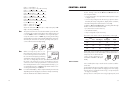
CONNECTIONS PANEL
FRONT PANEL
1. Liquid Crystal Display
2. LCD key
exits from setup and calibration modes and reverts back to
normal mode (in idle or control phases with the measurement on the display). In HI 21 series, during pH calibration,
alternately displays pH buffer value or current temperature
3. CAL DATA key
last calibration data viewing (enters and exits)
4. SETUP key
enters setup mode
5. CAL key
initiates and exits calibration mode
6. ñ key
increases the blinking digit/letter by one when selecting a
parameter. Advances forward while in last calibration data
viewing mode. Increases the temperature setting when
temperature probe is not inserted
7. ð key
moves to the next digit/letter (circular buffer) when selecting a parameter. Same as ñ key during last calibration
data viewing mode
8. ò key
decreases the blinking digit/letter by one when selecting a
parameter. Reverts backward while in last calibration data
viewing mode. Decreases the temperature setting when
temperature probe is not inserted
9. CFM key
confirms current choice (and skips to the next item)
10. BNC Socket
11. LEDs
6
1.
2.
3.
4.
5.
6.
7.
8.
9.
4-pin RS485 terminal (not for HI 21XY1 and HI 22XY1)
Analog output (not for HI 21XY2 and HI 22XY2)
Connections for Pt 100 temperature sensor
±5V power supply output
Connection for Potential Matching Pin
Connection for electrode reference
Power supply input (1 Potential Earth, 2 Neutral, 3 Line)
Alarm terminal (1 F.S. Closed, 2 COM, 3 F.S. Open)
Relay 1 - first dosing terminal (not for HI 21523) - (1 Normally Open, 2 COM,
3 Normally Closed)
10. Relay 2 - second dosing terminal (HI 212XY models only) - (1 Normally Open,
2 COM, 3 Normally Closed)
Unplug the meter before starting any electrical connections.
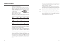
MECHANICAL DIMENSIONS
FRONT VIEW
BOTTOM VIEW
7
SPECIFICATIONS HI 21 & HI 22
Range
0.00 to 14.00 pH (HI 21 Series only)
±2000 mV (HI 22 Series only)
-9.9 to 120.0 °C
Resolution
0.01 pH (HI 21 Series only)
1 mV (HI 22 Series only)
0.1 °C
Accuracy
±0.02 pH (HI 21 Series only)
±2 mV (HI 22 Series only)
±0.5 °C
(@20°C/68°F)
8
Typical EMC Deviation
±0.05 pH (HI 21 Series only)
±4 mV (HI 22 Series only)
±1.0 °C
Analog Output
0 to 1 mA, 0 to 20 mA, 4 to 20 mA
0 to 5 VDC, 1 to 5 VDC, 0 to 10 VDC
Digital Output
RS485
Power Supply Input
±5V (for amplified electrodes)
Power Supply
230 ±10% VAC or 115 ±10% VAC, 50/60 Hz
Power Consumption
15 VA
Over Current Protection
400 mA, 250V, FAST FUSE
Relays 1 and 2
Electromechanical relay SPDT contact outputs,
5A-250 VAC, 5A - 30 VDC (resistive load)
(HI 211YZ, HI 212YZ and HI 221YZ)
Fuse protected: 5A, 250V FAST FUSE
Alarm Relay
Electromechanical relay SPDT contact output,
5A - 250 VAC, 5A - 30 VDC (resistive load)
Fuse protected: 5A, 250V FAST FUSE
Environment
0-50 °C; max 85% RH not condensing
Protection
IP 54
Dimensions
221 x 181 x 86 mm (8.7 x 7.1 x 3.4’’)
Weight
approximately 1.4 Kg (3.1 lb.)
INSTALLATION
HI 21 and HI 22 offer
a multitude of possibilities, from single and
dual setpoints to ON/
OFF, proportional or
PID dosage, isolated
outputs with user-selectable
zoom,
bidirectional RS485, recorder outputs in
mAmps and Volts.
In addition, HI 21 and
HI 22 are both
equipped with the exclusive differential
input.
In a system with poor
grounding, it is possible
to have a ground current flowing through
the reference junction.
This can cause a rapid
degradation of the electrode. The Hanna
differential input reduces the likelihood of
ground loops.
See the diagram for a
recommended installation.
9
• Power Supply: Connect a 3-wire power cable
to the terminal strip, while paying attention to
the correct line (L), earth (PE) and neutral (N)
terminal connections.
Power: 115VAC - 100 mA / 230VAC - 50 mA.
Line Contact: fused inside 400 mA.
PE must be connected to ground; leakage current 1
mA.
• Electrode: Connect the pH or ORP electrode to the BNC
socket (#10 at page 6).
To benefit from the differential input, connect the proper
electrode wire (if available)
or a cable with a potential
matching pin (grounding bar) to the relevant terminal (#5
at page 7).
Note
Note
10
When it is not possible to immerse the Potential Matching Pin
together with the pH electrode in the solution, disable the
differential input by connecting the Connection for Potential
Matching Pin (#5 page 7)
with the Connection for Electrode Reference (#6 on
page 7) with a jumper wire.
• Pt 100 Terminals: these contacts (#3 at page 7) connect
the Pt 100 temperature sensor for automatic temperature
compensation of pH measurement. In the case of shielded wire,
connect the shield to pin 4.
In the case of a 2-wire sensor connect the Pt 100 to pins 1 and 3,
and short pins 2 and 3 with a
jumper wire.
If the Pt 100 has more than 2
wires, connect the two wires of one
end to pins 2 and 3 (pin 2 is an
auxiliary input to compensate for the cable resistance) and
one wire from the other end to pin 1.
Leave the fourth wire unconnected, if
present.
• Power Supply Output: these terminals provide +5V and 5V DC (max current: 10 mA) signals to supply power to
amplified electrodes.
All cables connected to the panel should end with cable lugs.
SETUP MODE
HI 21 and HI 22 offer a multitude of possibilities from ON/
OFF, proportional or PID dosage to analog recorder output
and from alarm to selftest features.
The Setup Mode allows the user to set all needed characteristics of the meter.
The setup mode is entered by pressing SETUP
and entering the password when the device
is in idle or control mode.
Generally speaking, if the password is not inserted the user
can only view the setup parameters (except for password)
without modifying them (and the device remains in control
mode). An exception is certain setup items, or flags, which
can activate special tasks when set and confirmed.
Each setup parameter (or setup item) is assigned a twodigit setup code which is entered and displayed on the
secondary LCD.
The setup codes can be selected after password and CFM
are pressed. When CFM is pressed, the current setup item is
saved on EEPROM and the following item is displayed.
Whenever LCD is pressed, the device reverts back to control mode.
The same is true when CFM is
pressed on the last setup item.
The possible transitions in setup mode are the following:
ENTERING THE PASSWORD
• Press SETUP to enter the setup mode. The LCD will display
“0000” on the upper part and “PAS” on the lower. The first
digit of the upper part of the LCD will blink.
• Enter the first digit of the password by the ñ or ò keys.
11
• Then confirm the displayed digit with
ð and move to the next one.
• When the whole password has been
inserted, press CFM to confirm it.
Note
The default password is set at “0000”.
• The LCD will display “SET” on the
upper part and “c.00” on the lower,
allowing the user to edit setup parameters (see table below).
• After confirmation, the selected parameter is displayed. The user can scroll
through the parameters by pressing CFM.
In order to directly set another parameter, press SETUP again and enter the
code or scroll to it by pressing CFM.
The following table lists the setup codes along with the description of the specific setup items, their valid values and whether
password is required to view that item (“PW” column):
Code
• Enter the code of the parameter you want to set, using the
arrow keys as per the password procedure above (e.g. 41).
• Confirm the code by pressing CFM and the default or the
previously memorized value will be displayed with the first
digit blinking.
Note
When the password is not inserted or a wrong password is
confirmed, the display will only show the previously memorized value, without blinking (read only mode). In this case,
the value cannot be set. Press LCD and start again.
• Enter the desired value using the arrow keys and then press
CFM.
Valid Values
Default
00 Factory ID
0 to 9999
0000
no
01 Process ID
0 to 9999 (models w/o RS485) 0000
0 to 99 (models with RS485) 00
no
no
02 Control enable/disable
0: C.M. disabled
1: C.M. enabled
0
no
11 Relay 1 mode
(M1)
0: disabled
1: ON-OFF high setpoint
2: ON-OFF low setpoint
3: PID, high setpoint
4: PID, low setpoint
0: disabled
1: PID, high setpoint
2: PID, low setpoint
0
no
12 Relay 1 setpoint
(S1)
0.00 to 14.00 pH
-2000 to 2000 mV
8.00 pH
500 mV
no
13 Relay 1 hysteresis
(H1)
0.00 to 14.00 pH
0 to 4000 mV
1 pH
50 mV
no
14 Relay 1 deviation
(D1)
0.50 to 14.00 pH
25 to 4000 mV
1 pH
50 mV
no
15 Relay 1 reset time
(HI 21523 only)
0.1 to 999.9 minutes
999.9 mins
no
16 Relay 1 rate time
(HI 21523 only)
0.0 to 999.9 minutes
0.0 mins
no
21* Relay 2 mode (M2)
same as relay 1
0
no
22* Relay 2 setpoint (S2)
0.00 to 14.00 pH
-2000 to 2000 mV
6.00 pH
-500 mV
no
for HI 21523 only :
PW
* Available only in models with two relays
12
13
Code
Valid Values
Default
PW
Code
Valid Values
Default
PW
23* Relay 2 hysteresis (H2)
0.00 to 14.00 pH
0 to 4000 mV
1 pH
50 mV
no
60 Current day
01 to 31
from RTC
no
61 Current month
01 to 12
from RTC
no
24* Relay 2 deviation (D2)
0.50 to 14.00 pH
25 to 4000 mV
1 pH
50 mV
no
62 Current year
1997 to 9999
from RTC
no
63 Current time
00:00 to 23:59
from RTC
no
25* Relay 2 reset time
(HI 21523 only)
0.1 to 999.9 minutes
999.9 mins
no
71 Baud rate
1200, 2400, 4800, 9600
9600 (RS485) no
26* Relay 2 rate time
(HI 21523 only)
0.0 to 999.9 minutes
0.0 mins
no
90 Display selftest
0: off
1: on
0
yes
30 Relay 3 high alarm (HA) 0.00 to 14.00 pH
9.00 pH
-2000 to 2000 mV
600 mV
HA>LA, HA>S1 or HA>S2
no
91 Keyboard selftest
0: off
1: on
0
yes
92 EEPROM selftest
0
yes
31 Relay 3 low alarm (LA)
0.00 to 14.00 pH
5.00 pH
-2000 to 2000 mV
-600 mV
LA<HA, LA<S1 or LA<S2
no
0: off
1: on
93 Relays and LEDs selftest
0: off
1: on
0
yes
32 Proportional control
mode period
1 to 30 min (not for HI 21523)
5 s to 30 min (HI 21523 only)
no
no
94 Watchdog selftest
0: off
1: on
0
yes
60
33 Maximum relay ON time 1 to 60 min (HI 21523 only)
10 to 999 min (not for HI 21523) 60
(after which an alarm mode is entered)
no
no
99 Unlock password
0000 to 9999
0000
yes
34 Alarm mask time
(HI 21523 only)
no
00:00 to 30:00
5 min
30 s
00:00
40 Analog output selection
0: 0-1mA
2
no
1: 0-20 mA
2: 4-20 mA
3: 0-5 VDC
4: 1-5 VDC
5: 0-10 VDC
Note: this parameter refer to internal hardware configuration of the instrument. To
change it from the factory setting, see page 26.
14
41 Analog output
lower limit
(O_VARMIN)
0.00 to 13.00 pH
0.00 pH
no
-2000 to 2000 mV
-2000 mV
(O_VARMIN < O_VARMAX-(1.00pH or 50mV))
42 Analog output
upper limit
(O_VARMAX)
1.00 to 14.00 pH
14.00 pH
no
-2000 to 2000 mV
2000 mV
(O_VARMIN < O_VARMAX- (1.00pH or 50mV))
Note
The process controller automatically checks to ensure that
the entered data matches other related variables. If a wrong
configuration is entered, “WRONG” blinks on the LCD to
prompt the user. The correct configurations are the following:
If M1=
/ 0 then S1<HA, S1>LA;
If M2=
/ 0 then S2<HA, S2>LA;
For models other than HI 21523:
If M1= 1 then S1-H1>LA;
If M1= 2 then S1+H1<HA;
If M1= 3 then S1+D1<HA;
If M1= 4 then S1-D1>LA;
If M2= 1 then S2-H2>LA;
If M2= 2 then S2+H2<HA;
If M2= 3 then S2+D2<HA;
If M2= 4 then S2-D2>LA;
If M1= 1 and M2 = 2
then S1-H1>S2+H2, S2>LA, HA>S1;
If M1 = 2 and M2 = 1
then S2-H2>S1+H1, S1>LA, HA>S2;
If M1 = 3 and M2 = 2
then S1>S2+H2, S2>LA, HA>S1+D1;
15
If M1 = 2 and M2 = 3
then S1+H1<S2, S1>LA, HA>S2+D2;
If M1 = 4 and M2 = 1
then S1<S2–H2, S1–D1>LA, HA>S2;
If M1 = 1 and M2 = 4
then S1–H1>S2, S2–D2>LA, HA>S1;
If M1 = 3 and M2 = 4
then S1>S2, S2–D2>LA, HA>S1+D1;
If M1 = 4 and M2 = 3
then S2>S1, S1–D1>LA, HA>S2+D2;
For HI 21523 only:
If M1 = 1 then S1+D1<HA;
If M1 = 2 then S1–D1>LA;
where the minimum deviation (D1 or D2) is 0.5 pH (for HI
21) or 25 mV (for HI 22).
Note
Note
Note
16
CONTROL MODE
The control mode is the normal operational mode for these
meters. During control mode HI 21 and HI 22 fulfill the
following main tasks:
• convert information from pH/ORP and temperature inputs
to digital values;
• control relays and generate the analog outputs as determined by the setup configuration, display alarm condition;
• RS485 management (if the feature is included).
In addition, HI 21 and HI 22 can log working data through
RS485 connection. This data includes:
• pH, mV and oC measured values;
• last calibration data;
• setup configuration (also from PC).
The status of the meter is shown by the LED’s on the right
The password cannot be viewed when SETUP is pressed without entering the original password first. The default password
is set at “0000”. In the event that the user forgets the password, this can be reset to “0000” by pressing and holding
CFM and then pressing LCD and CAL DATA at the same time
when the pH controller is in normal operating mode (idle or
control with measurement displaying).
When a wrong setup value is confirmed, the pH controller does not skip
to the next setup item but remains in
the current item displaying a flashing
“WRONG” indicator until the parameter value is changed by the user (the same is also true for
the setup code selection). In some circumstances, the user
cannot succeed in setting a parameter to a desired value if
the related parameters are not changed beforehand; e.g. to
set a pH high setpoint to 10.00 the high alarm must be set to
a value greater than pH 10.00 first.
For code numbers 40, 41, 42, the output is related to pH or mV units
depending on the model (pH process meters or mV process meters).
Items 41 and 42 are not available in HI 215YZ .
STATUS
LEDs
Alarm LED (green) Relay LED (yellow)
Control
Alarm
Red LED
OFF
----
ON
OFF
ON
ON
OFF
ON
ON or OFF
OFF
ON
ON
OFF
ON or OFF
Blinking
Meter exits control mode by pressing SETUP or CAL and confirming the password. Note that this command generates a
temporary exit. To deactivate the
control mode definitively, set
CONTROL ENABLE to “0” (item
# 02).
RELAY MODES
Once enabled, the relays 1 and 2 can be used in four different modes:
1) ON/OFF, high setpoint (acid dosage) (not for HI 21523);
2) ON/OFF, low setpoint (base dosage) (not for HI 21523);
3) Proportional or PID (HI 21523 only), low setpoint (base
dosage, if available);
4) Proportional or PID (HI 21523 only), high setpoint (acid
17
dosage, if available).
An upper boundary is imposed for acid/base dosage time
when relays are energized continuously, i.e. when relay works
in ON/OFF mode or in PID mode but in the latter case only
if the relay is always ON. This parameter can be set through
setup procedure. When the maximum boundary is reached,
an alarm is generated; device stays in alarm condition until
relay is de-energized.
ON/OFF CONTROL MODE
Either for mode 1 or 2 (base or acid dosage) the user has to
define the following values through setup:
• relay setpoint (pH/mV value);
• relay hysteresis (pH/mV value).
Connect your device to the COM and
NO (Normally Open) or NC (Normally
Closed) terminals.
The ON relay state occurs when relay is energized (NO and
COM connected, NC and COM disconnected).
The OFF relay state occurs when relay is de-energized (NO
and COM disconnected, NC and COM connected).
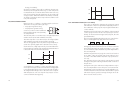
The following graphs show relay states along with pH measured value (similar graph can be derived for mV control).
As shown below, a high setpoint relay is activated when the
measured pH exceeds the setpoint and is deactivated when it
is below the setpoint value minus hysteresis.
ON
OFF
Setpoint –
Hysteresis
Setpoint
14
Such a behavior is suitable to control an acid dosing pump.
A low setpoint relay as can be seen from the following graphs
is energized when the pH value is below the setpoint and is
de-energized when the pH value is above the sum of setpoint
and the hysteresis. The low setpoint relay may be used to
control an alkaline dosing pump.
18
ON
OFF
Setpoint
Setpoint +
Hysteresis
14
P.I.D. CONTROL MODE (HI 21523 ONLY)
PID control is designed to eliminate the cycling associated
with ON/OFF control in a rapid and steady way by means of
the combination of the proportional, integral and derivative
control methods.
With the proportional function, the duration of the activated
control is proportional to the error value (Duty Cycle Control
Mode): as the measurement approaches setpoint, the ON
period diminishes.
The following graph describes the pH process controller behavior. Similar graph may apply to the mV controller.
t0
t0+Tc
t0+2Tc
t0+3Tc
During proportional control the process controller calculates
the relay activation time at certain moments t0, t0+Tc, t0+2Tc
etc. The ON interval (the shaded areas) is then dependent to
the error amplitude.
With the integral function (reset), the controller will reach a
more stable output around the setpoint providing a more
accurate control than with the ON/OFF or proportional action only.
The derivative function (rate action) compensates for rapid
changes in the system reducing undershoot and overshoot of
the pH value.
During PID control, the ON interval is dependent not only to
the error amplitude but even to the previous measurements.
Definitely PID control provides more accurate and stable control than ON/OFF controllers and it is best suitable in system
with a fast response, quickly reacting to changes due to addition of acid or base solution.
19
An example of how the response overshoot can be improved with
a proper rate action setting is depicted in the following graphic.
In HI 21 and HI 22 the proportional action is set directly as
“Deviation” in pH and mV units respectively. Relation between Deviation (D) and PB is:
D = Range * PB/100
Each setpoint has a selectable proportional band: PB1 for
setpoint1 and PB2 for setpoint2. Two further parameters must
be provided for both setpoints:
Ti = Kp/Ki, reset time, measured in minutes
Td = Kd/Kp, rate time, measured in minutes.
Ti1 and Td1 will be the reset time and rate time for setpoint1,
while Ti2 and Td2 will be the reset time and the rate time for
setpoint2.
pH
RATE ACTION COMPENSATES FOR RAPID CHANGES
t
PID TRANSFER FUNCTION
The transfer function of a PID control is as follows:
Kp + Ki/s + s Kd = Kp (1 + 1/(s Ti) +s Td)
with Ti = Kp/Ki, Td = Kd/Kp,
where the first term represents the proportional action, the
second is the integrative action and the third is the derivative
action.
Proportional action can be set by means of the Proportional
Band (PB). Proportional Band is expressed in percentage of the
input range and is related to Kp according to the following:
Kp = 100/PB.
TUNING A PID CONTROLLER
The proportional, integrative, derivative terms must be tuned,
i.e. adjusted to a particular process. Since usually the process variables are not completely known, a “trial and error”
tuning procedure must be applied to get the best possible
control for the particular process. The target is to achieve a
fast response time and a small overshoot.
Many tuning procedures are available and can be applied
to HI 21. A simple and profitable procedure is reported in
this manual and can be used in almost all applications.
The user can vary five different parameters, i.e. the setpoint
(S1 or S2), the deviation (D1 or D2), the reset time, the rate
time and the proportional control mode period Tc (from 1 to
30 minutes).
Note
User can disable the derivative and/or integrative action (for
P or PI controllers) by setting Td = 0 and/or Ti = MAX (Ti)
respectively through the setup procedure.
SIMPLE TUNING PROCEDURE
The following procedure uses a graphical technique of analyzing a process response curve to a step input.
100%
Controller
output
Note
0
Connecting an external device (chart recorder or PC) to the
controller, the procedure is easier and doesn’t need the use
of hand plotting the process variable (pH or mV).
Error
Proportional Band
20
21
1. Starting from a solution with a pH or mV value different
from the dosed liquid (at least a 3 pH or 150 mV difference) turn on the dosing device at its maximum capacity
without the controller in the loop (open loop process). Note
the starting time.
2. After some delay the pH or mV starts to vary. After more
delay, the pH or mV will reach a maximum rate of change
(slope). Note the time that this maximum slope occurs and
the pH or mV value at which it occurs. Note the maximum
slope in pH or mV per minute. Turn the system power off.
3. On the chart draw a tangent to the maximum slope point until
intersection with the horizontal line corresponding to the initial
pH or mV value. Read the system time delay Tx on the time axis.
4. The deviation, Ti and Td can be calculated from the following:
• Deviation = Tx * max. slope (pH or mV)
• Ti = Tx / 0.4 (minutes)
• Td = Tx * 0.4 (minutes).
5. Set the above parameters and restart the system with the
controller in the loop. If the response has too much overshoot or is oscillating, then the system can be fine-tuned
slightly increasing or decreasing the PID parameters one
at a time.
Example:
the chart recording in the figure
aside was obtained continuously
dosing an alkaline solution to a
weak acid solution in a tank. The
initial settings will be:
Max. slope = 3 pH/5 mins = 0.6
pH/min
Time delay = Tx = approx. 7 mins
Deviation = Tx * 0.6 = 4.2 pH
Ti = Tx / 0.4 = 17.5 mins
Td = Tx * 0.4 = 2.8 mins
22
ALARM RELAY
The alarm relay functions in the following manner:
During alarm condition, the relay is de-energized. When not
in alarm condition, the relay is energized.
FS•C = NO (Normally Open)
Energized Relay
COM
FS•O = NC (Normally Closed)
De-energized Relay
Example:
High alarm set at 10 pH
Low alarm set at 4 pH
An hysteresis will eliminate the possibility of continuous sequences ‘energizing/de-energizing’ of the alarm relay when
the measured value is close to the alarm setpoint. The hysteresis amplitude is 0.2 pH in HI 21 and 30 mV in HI 22.
Moreover the alarm signal is generated only after a user selectable time period (alarm mask) has elapsed since the
controlled value has overtaken one alarm threshold. This
additional feature will avoid fake or temporary alarm conditions.
Note
If the power supply is interrupted, the relay is de-energized as
if in alarm condition to alert the operator.
In addition to the user-selectable alarm relays, all HI 21 and
HI 22 models are equipped with the Fail Safe alarm feature.
The Fail Safe feature protects the process against critical
errors arising from power interruptions, surges and human
errors. This sophisticated yet easy-to-use system resolves these
predicaments on two fronts: hardware and software. To eliminate problems of blackout and line failure, the alarm function
operates in a “Normally Closed” state and hence alarm is
triggered if the wires are tripped, or when the power is down.
23
This is an important feature since with most meters the alarm
terminals close only when an abnormal situation arises, however, due to line interruption, no alarm is
sounded, causing extensive damage. On
the other hand, software is employed to
set off the alarm in abnormal circumstances, for example, if the dosing terminals
are closed for too long a period. In both
cases, the red LED’s will also provide a
visual warning signal.
The Fail Safe mode is accomplished by connecting the external alarm circuit between the FS•O (Normally Open) and
the COM terminals. This way, an alarm will warn the user
when pH goes over the alarm thresholds, the power breaks
down and in case of a broken wire between the process meter
and the external alarm circuit.
IDLE MODE
During idle mode the device performs the same tasks as when
it is in control mode except for the relays. The alarm relay is
activated (no alarm condition), the acid and base relays are
not activated while the analog output remains activated.
When the instrument is in idle mode the red and green status
LEDs are on.
Idle mode is useful to disable control actions when the external devices are not installed or when the user detects unusual
circumstances.
Control actions are stopped as soon
as the user presses SETUP and enters
the password.
Note
In order to have the Fail Safe feature activated, an external
power supply has to be connected to the alarm device.
CONTROL THROUGH ANALOG OUTPUT
Model HI 21523 has a proportional output signal (selectable among 0-1 mA, 0-20 mA, 4-20 mA, 0-5 VDC, 1-5
VDC and 0-10 VDC) at the analog output terminals. With
this output, the actual output level amplitude is varied, rather
than the proportion of ON and OFF times (duty cycle control). A device with analog input (e.g. a pump with a 4-20
mA input) can be connected to these terminals.
Note
24
In order to reactivate the control mode, use code 02 of setup
(see “Setup” section). Otherwise, the meter remains in idle
mode.
Models with this feature don’t have the output relay for a duty
cycle control.
25
These values can be changed by the user to have the analog
output matching a different pH range, for example, 4 mA =
3.00 pH and 20 mA = 5.00 pH.
To change the default values, the setup mode must be entered. Setup codes for changing the analog output minimum
and maximum are 41 or 42, respectively. For the exact
procedure, refer to the setup mode section in the manual.
ANALOG OUTPUT
All models HI 21XY1, HI 21XY3 and HI 22XY1 are provided
with the analog output feature.
The output is isolated and can be a voltage or a current.
With the recorder, simply connect the common port to the
ground output and the second port to the current output or
voltage output (depending on
which parameter is being used)
as depicted aside.
The type (voltage or current)
and the range of the output
analog signal is selectable through the jumpers on the power
board.
Configurations of the jumpers are as follows:
Output
Jumper 1
Jumper 2
Jumper 3
Jumper 4
0-5 VDC, 1-5 VDC
OFF
ON
––
––
0-10 VDC
ON
OFF
––
––
0-20 mA, 4-20 mA
––
––
ON
––
0-1 mA
––
––
OFF
––
Note
The difference between maximum and minimum values for
the analog output must be at least 1.00 pH or 50 mV.
Note
The analog output is factory calibrated through software. The
user may also perform these calibration procedures following
the procedure at page 46. It is recommended to perform the
output calibration at least once a year.
Choice between different ranges with the same configuration
(for example 0-20 mA and 4-20 mA) is achieved via software by entering the setup mode and selecting code 40 (see
Setup Mode section for exact procedure).
Factory default is jumpers 1 and 3 closed (ON) and jumpers
2 and 4 open (OFF), i.e. 0-20 mA, 4-20 mA and 0-10
VDC.
In any case, contact the nearest Hanna Customer Service
Center for changing of the default configuration.
By default the minimum and maximum values of analog
output correspond to the minimum and maximum of the
range of the meter. For example, for the HI 21 series with a
selected analog output of 4-20 mA, the default values are
0.00 and 14.00 pH corresponding to 4 and 20 mA, respectively.
26
27
RS485 COMMUNICATION
HI 21XY2, HI 21XY3 and HI 22XY2 are provided with an
RS485 port.
RS485 standard is a digital transmission method that allows
long lines connections. Its current-loop system makes this
standard suitable for data transmission in noisy environments.
Data transmission from the instrument to the PC is possible
with the HI 92500 Windows® compatible application software offered by Hanna Instruments.
The user-friendly HI 92500 offers a variety of features such
as logging selected variables or plotting the recorded data. It
also has an on-line help feature to support you throughout
the operation.
HI 92500 makes it possible for you to use the powerful means
of the most diffused spreadsheet programs (Excel©, Lotus
1-2-3© etc.). Simply run your favorite spread sheet and open
the file downloaded by HI 92500. It is then possible to elaborate the data with your software (e.g. graphics, statistical
analysis).
To install HI 92500 you need a 3.5" drive and few minutes
to follow the instructions conveniently printed on the disk’s
label.
Contact your Hanna Dealer to request a copy.
SPECIFICATIONS
The RS485 standard is implemented in HI 21/HI 22 with the
following characteristics:
Data rate:
up to 9600 bps
Communication:
Bidirectional Half-Duplex
Line length:
up to 1.2 Km typ. with 24AWG cable
Loads:
up to 32 typ.
Internal termination: none
CONNECTIONS
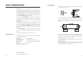
The connections for the 4-pin RS485 terminal provided (#1
on page 7) are as follows:
The instrument has no internal line termination. To terminate
the line, an external resistor equal to the characteristic line
impedance (typically 120Ω) must be added at both ends of
the line.
Up to 32 units can be connected to the same RS485 line,
with a total line length of up to 1.2 Km using 24AWG cable.
To minimize electromagnetic interferences, use shielded or
twisted pair cable to connect the units.
Each HI 21/HI 22 unit is identified by its process ID number
(setup item “01”).
The HI 21/HI 22 controller acts as a “slave” device: it only
answers to commands received from a “master” device (e.g.
an industrial PC) connected to the line.
Excel© Copyright of “Microsoft Co.”
Lotus 1-2-3© Copyright of “Lotus Co.”
Windows® registered Trademark of “Microsoft Co.”
28
29
As additional feature, the controller is also
provided with two pins (5V and 0V) in order to apply the Fail Safe Open Line
protection method. To avoid erroneous
readings in Open-Line conditions, pullup and pull-down resistors should be
connected as shown.
Command
Parameter
CAR
null
Request calibration data
GET
NN
Request setup item NN
K 01
null
Same as CFM+ð+CAL keys
K 02
null
Same as LCD+CAL+SETUP keys
KCD
null
Same as CAL DATA key
KCF
null
Same as CFM key
KCL
null
Same as CAL key
KDS
null
Same as LCD key
KDW
null
Same as ò key
KRG
null
Same as ð key
KST
null
Same as SETUP key
KUP
null
Same as ñ key
MDR
null
Request firmware code
MVR
null
Request mV reading
(HI 22 only; available in
control or idle mode only)
A maximum time interval of 20 ms is allowed between two
consecutive characters of a command.
PHR
null
Request pH reading
(HI 21 only; available in
control or idle mode only)
It is possible to send commands to change the controller
settings or to simply ask information on the controller status.
PWD
NNNN
Send the 4-digit password
The Fail-Safe resistors are connected only to one unit in the
line, and their value depends on the application and characteristic impedance of the connection cable.
The RS485 port is optoisolated from measuring circuit and
power line. If both analog output and RS485 port are present,
they have the same ground.
RS485 PROTOCOL
The commands sent to the controller must have the following
format:
• 2-digit process ID number
• 3-character command name
• Parameters (variable length, may be null)
• End of command (always the CR character, Hex 0D)
Description
SET
Following is the complete list of commands available:
30
NNPC1C2C3C4C5 Set setup item NN to the
PC1C2C3C4C5 value
P=+ if value is greater than 0
P=- if value is less than 0
C1 can be 0 or 1 only
C2C3C4C5 can be 0 to 9 or
blank
(the command is
not available if
the controller is
in setup mode)
31
TMR
null
Request temperature reading
Note
If the controller is not in control or idle mode and the temperature reading is requested through the TMR command,
the controller answers with the last acquired reading when it
was in control or idle mode.
Note
After a recognized PWD command is received, the controller
allows a maximum of 1 minute without receiving data, after
which it locks again and a new PWD command is needed to
perform password protected operations.
Following are examples of commands for setup items:
1) “03 SET 22-01200<CR>”
This command sets the setup item 22 (relay 2 setpoint) of
a mV controller, identified by the process ID number 03,
to the -1200 mV value.
2) “01 SET 33+015 ◊ ◊ <CR>”
This command sets the setup item 33 (max. relay ON
time) of a controller, identified by the process ID number
01, to 15 minutes. The “◊ ” character means blank.
Once the controller has received a command, it answers
with its 2-digit process ID number followed by:
• ACK (Hex 06)
If the controller recognizes the received command
and performs the requested task;
• STX (Hex 02) , Data , ETX (Hex 03)
If the received command is a request of data;
• NAK (Hex 15)
If the received command is not recognized (e.g. the
syntax is wrong);
• CAN (Hex 18)
If the controller cannot answer the request (e.g. the
password was not sent, the controller is in setup
mode, the setup item is not available in that model,
etc.)
32
Note
The controller answers to the GET command with the same
data format explained in the SET command.
Following are examples of answers:
1) “03<STX>-01200<ETX>”
The controller with process ID number 03 says that its
current setpoint is -1200 mV.
2) “01<STX>UHI2122210<ETX>”
The controller with process ID number 01 says that it is a
HI 21222 model with firmware release 1.0.
The time-out for the first character of the controller answer is
2 seconds (except answers to PHR, MVR and TMR as explained below).
The minimum delay between the last received character and
first character of the answer is 15 ms.
The time-out for the complete controller answer to the PHR,
MVR and TMR commands is:
30 ms at 9600 bps
40 ms at 4800 bps
60 ms at 2400 bps
90 ms at 1200 bps
When the controller answers to the PHR, MVR and TMR commands, the reading is sent as ASCII string followed by a
character (HI 21523 only) indicating the control and alarm
status of the controller. This character can assume the following values:
• “A”, control and alarm are ON;
• “C”, control is ON and alarm is OFF;
• “N”, control and alarm are OFF;
For example, a possible answer to the TMR command is:
“03<STX>10.7C<ETX>”
33
HI 22: 1<Date><Time><Buf1><Buf2>
• Date:
• Time:
• Buf 1:
• Buf 2:
DDMMYY (e.g. “170400” for April 17,2000)
HHMM (e.g. “1623” for 4:23 pm)
ASCII string (e.g. “7.01”)
ASCII string (e.g. “4.01”)
The items in the Data field are separated by blanks.
If an item is not available (e.g. Buf 3 if only a two points
calibration was performed) it is replaced by the “N” character.
Note
pH CALIBRATION (for HI 21 Series only)
The pH controller can be calibrated through a one-point,
two-point or three-point calibration. You do not need to enter the method chosen, simply exit the
calibration mode, by pressing CAL,
when the desired number of points has
been calibrated.
The calibration points for HI 21 are pH 4.01, pH 7.01 and
pH 10.01 (at 25°C). The sequence proposed by the controller is pH 7.01, pH 4.01, pH 10.01. However, the user can
change this sequence by means of the ñ and ò keys.
The electrode must be kept hydrated at all times and definitely prior to calibration. The temperature probe should also
be connected to the process meter. The meters are equipped
with a stability indicator. The user is also guided with indications on the display during the calibration procedure.
Initial Preparation
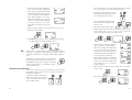
Pour small quantities of pH 7.01
(HI 7007) and pH 4.01 (HI 7004)
and/or pH 10.01 (HI 7010) solutions
into individual beakers. If possible, use
plastic beakers to minimize any EMC
interference.
04
• Date: DDMMYY (e.g. “170400” for April 17,2000)
• Time: HHMM (e.g. “1623” for 4:23 pm)
• Offset: ASCII string (e.g. “-0.2”)
• Slope 1: ASCII string (e.g. “62.5”)
• Slope 2: ASCII string (e.g. “60.4”)
• Buf 1: ASCII string (e.g. “7.01”)
• Buf 2: ASCII string (e.g. “4.01”)
• Buf 3: ASCII string (e.g. “10.01”)
The controller is factory calibrated for mV and temperature
inputs as well as for the analog outputs.
The user should periodically calibrate the instrument. For greatest accuracy, it is recommended that the instrument is calibrated
frequently.
It is possible to standardize the electrode with only one buffer,
preferably close to the expected sample value (one-point calibration), but it is always good practice to calibrate in at least
2 points.
70
HI 21:
1<Date><Time><Offset><Slope1><Slope2><Buf1><Buf2><Buf3>
CALIBRATION
HI
meaning that the current temperature reading is 10.7°C, the
control action is active and no alarm condition is present.
If asking for last calibration data and the controller was never
calibrated, it answers with “0”; e.g. “01<STX>0<ETX>”.
If the controller was calibrated, it answers with “1” followed
by the calibration data. The Data field of the answer has the
following format:
HI 7004
HI 7007
The “r485” message can appear on the LCD while the controller is receiving or answering commands.
SETTING THE BAUD RATE
The transmission speed (baud rate) of the meter and external
device must be the same.
The meter is factory set to 9600 bps. To change this value,
use setup item 71.
34
35
For accurate calibration, use two beakers for each buffer
solution, the first one for rinsing the electrode, the second
one for calibration. By doing this, contamination between
the buffers is minimized.
RINSE
CALIBRATION
HI 7007
HI 7007
To obtain accurate readings, use pH 7.01 and pH 4.01 if
you measure acidic samples, or pH 7.01 and pH 10.01 for
alkaline measurements or perform a 3-point calibration for
the entire range.
One Point Calibration (Offset)
• To perform the pH calibration enter
the calibration mode, by pressing
CAL and entering the password.
• After the correct password is entered,
the control actions stop and the primary LCD will display the pH value
using the current offset and slope,
with the "CAL" and " " indicators lit
and the probe indicator " " blinking. The value displayed on the
secondary LCD is the buffer value
at the actual temperature.
1
BUF
Note
Note
36
The actual pH value varies with temperature, thus the calibration value displayed on the secondary LCD will vary around
pH 4.01, 7.01 and 10.01 with temperature changes: for example at 25 oC the display shows 4.01 - 7.01 - 10.01, at 20
o
C it shows 4.00 - 7.03 - 10.06 (see page 57 for other values).
• Remove the protective cap from the
pH electrode and immerse it into the
selected buffer solution (e.g. pH 7.01)
with the Potential Matching Pin and
temperature probe, then stir gently.
Note
The electrode should be submerged approximately 4 cm (1½") in the solution.
The temperature probe should be located
as close as possible to the pH electrode.
Note
When it is not possible to immerse the Potential Matching Pin
together with the pH electrode in the solution, disable the
differential input by connecting the Connection for Potential
Matching Pin (#5 page 7) with the Connection for Electrode
Reference (#6 on page 7) with a jumper wire.
• Only when the reading is stable the
probe indicator " " will stop flashing
(after about 30 seconds) and the
"CFM" indicator will start blinking.
• Press CFM to confirm the calibration; if the reading is close to
the selected buffer (±1.5 pH), the meter stores the reading
and the secondary LCD will display the expected second buffer
value. Offset and slope calculation is made at the end by
pressing CAL to exit.
If the reading is not close to the selected
buffer, "WRONG " will blink.
BUF
• pH 7.01 is the default value for
the 1st calibration buffer. If a different value is needed, select it
on the secondary display by
pressing ñ or ò.
• If CAL is pressed, the calibration process ends by memorizing a new offset
value. The new offset value is stored
and a default value of 57.5 mV per
pH unit at 25°C is assigned as the
new slope value.
If the wrong password is entered the system reverts back and
restarts displaying the pH value.
For best accuracy however, it is recommended that a twopoint calibration is performed.
37
Two-point Calibration
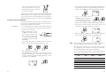
• Proceed as described above for one-point calibration, using pH 7.01 as the first point, but do
not quit calibration by pressing CAL at the end.
Note
Three-point Calibration
• Proceed as described above but do
not quit calibration by pressing CAL.
Note
The meter will automatically skip the buffer that was used for
the first calibration to prevent errors.
• After the second calibration point
is confirmed, immerse the pH electrode and the Potential Matching Pin
into the third buffer solution (e.g.
pH 10.01) and stir gently.
• After the first calibration point is confirmed, immerse the pH electrode with
the Potential Matching Pin into the second buffer (e.g. pH 4.01) and stir gently
Note
If you are not going to perform a three-point calibration, it is
recommendable to use pH 4.01 buffer if you are going to measure acid samples, or use pH 10.01 buffer for alkaline samples.
Note
The electrode should be submerged approximately 4 cm (1½") in the solution.
The temperature probe should be located
as close as possible to the pH electrode.
The meter will automatically skip the two buffers that were
used to prevent errors.
Note
The electrode should be submerged
approximately 4 cm (1½") in the solution. The temperature probe should
be located as close as possible to the
pH electrode.
• Only when the reading is stable the
probe indicator " " will stop flashing (after about 30 seconds) and the
"CFM" indicator will start blinking.
• Press CFM to confirm the calibration; if the reading is close
to the selected buffer, the meter stores the reading, adjusting the 2nd slope point and the calibration process is ended
with the offset and the 1st and 2nd slope of the meter calibrated.
• Select the 2nd buffer value on
the secondary display by pressing ñ or ò (e.g. pH 4.01).
• Only when the reading is stable
the probe indicator " " will stop
flashing (after about 30 seconds) and
the "CFM" indicator will blink.
• Press CFM to confirm the calibration; if the reading is close
to the selected buffer, the meter stores the reading, adjusting the slope point and the secondary LCD will display
the expected third buffer value.
If the reading is not close to the selected buffer, "WRONG " will
blink.
BUF
If the reading is not close to the selected buffer, "WRONG " will
blink.
BUF
Note
During calibration, the secondary LCD displays the selected
buffer value. By pressing LCD the temperature can be displayed. This will allow you to check the buffer temperature
during calibration.
• Press CAL and the calibration process is ended with the offset and the
1st slope of the meter calibrated.
38
39
CALIBRATION WITH MANUAL TEMPERATURE COMPENSATION
• Enter the calibration procedure and press LCD to display
the temperature on the secondary LCD.
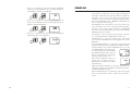
• Unplug any temperature probe that may
be attached to the meter. The "°C" symbol will flash.
• Note the temperature of the buffer solutions with a
ChecktempC or another accurate thermometer with a resolution of 0.1°C.
• Use ñ or ò to manually adjust the display reading to the
value of the reference thermometer (e.g. 20°C).
• Follow the calibration procedure above.
Note
If the process meter has never been calibrated or an EEPROM reset has occurred,
the meter continues to perform measurement. However, the user is informed of a pH calibration
requirement by a blinking “CAL” (see “Start-up” section).
The device must be calibrated within the temperature range
of 0-95°C. Outside this range, the buffer pH values are not
reliable.
40
1
BUF
To toggle between the pH buffer and
the temperature press LCD.
When a one-point calibration is carried out only the pH offset is computed and stored, while the pH slope is fixed
according to the theoretical values.
With a two-point calibration, offset and slope are computed
to fit the two calibration points. With a three-point calibration the offset and first slope values refers to pH 4.01 and
7.01 buffers, while the second slope refers to pH 7.01 and
10.01 buffers.
Note
PH BUFFER SELECTION (HI 21523 ONLY)
A one point pH calibration at a value different from standard
buffer is possible by directly entering the desired calibration
value.
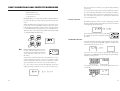
• Pour a small quantity of the calibration solution in a beaker and then
press CAL to enter the calibration
mode.
• After the correct password is entered,
the control action stops and the primary LCD will display the pH value
using the current offset and slope,
with the "CAL" and " " indicators
lit and the probe indicator " " blinking.
• Press SETUP and the pH value on
the secondary LCD will start blinking.
• By the ñ, ò and ð keys select the pH calibration value
of the buffer.
• Immerse the electrodes in the buffer solution.
• When the reading is stable press CFM to confirm the calibration.
Note
During calibration with pH buffer solutions different from standard, the stability check function is not active. No “CAL” or
" " indicators will blink, hence wait for the reading to stabilize after having immersed the electrode in the calibration
solution.
1
BUF
Note
If the wrong password is entered the system reverts back and
restarts displaying the pH value.
Note
Calibration can be aborted by pressing SETUP before CFM .
Calibration is restarted with no changes to calibration data.
41
OFFSET AND SLOPE DIRECT SELECTION (HI 21523 ONLY)
Whenever the pH electrode offset and slope parameters are
known, it is possible to directly calibrate the meter entering
the electrode parameters.
• Press the “CAL DATA” and then “SETUP”. The LCD will
show the default offset of -5.0 mV.
• Using the ñ, ò and ð enter the electrode offset parameter (the value must be between -100 and +100 mV).
• Confirm the value by pressing CFM.
If offset is invalid the “WRONG”
indicator will blink on the LCD.
• The LCD will then show the default
slope for Hanna electrodes: 57.5
mV/pH.
Note
If CAL DATA or LCD are pressed before CFM, calibration is
aborted without changing the data of previous calibration.
• Using the ñ, ò and ð enter the electrode slope parameter (the value must be between +40 and +80 mV/pH).
mV INPUT CALIBRATION
The pH/mV controller is factory calibrated for the mV and
temperature inputs. However, the user may also perform a
mV calibration.
• Short the Connection for Potential Matching Pin (#5 on
page 7) and the Connection for the Electrode Reference
(#6 on page 7) with a jumper wire.
• Attach a HI 931001 (HI 21) or HI 8427 (HI 22) simulator
to the BNC socket.
• Press and hold first CFM and then
CAL to enter the mV Input Calibration mode.
• Execute the password procedure.
• With HI 21, the meter will ask for the calibration procedure code number. The following table lists the possible
values of the input code and calibration points:
INPUT
CODE
POINTS
CAL.VALUES
INPUT RANGE
mV
0
2
0 & 350 or 0 & 1900*
±2000,
Temp.
1
2
0 & 25 or 0 & 50 -9.9 to 120.0 °C
* One of the points must be 0. 1900 mV calibration point is available
on HI 22 models only.
When calibrating the mV of HI 22 models, enter the calibration mode by pressing CAL and confirming the password
(as for pH calibration of HI 21). No code selection is required.
• Use ñ or ò to select code 0 for mV calibration and press
CFM to enter.
• Confirm the value by pressing CFM. If
slope is invalid the “WRONG” indicator will blink on the LCD.
42
Note
Press LCD or CAL DATA to exit calibration. The slope will be set to the
default value (57.5 mV/pH).
Note
Calibration data can be viewed pressing CAL DATA while in
normal mode but no pH buffer values will be displayed during the data scrolling on LCD.
• CAL will blink on the LCD until the
meter confirms a steady reading.
43
• When the reading has stabilized at
a point near the first calibration
point, CAL will stop blinking and an
intermittent CFM icon will prompt the
user to confirm the first calibration.
• If the display stabilizes at a value
significantly different from the first
setpoint, an intermittent WRONG
icon will prompt the user to check
and adjust the simulator and start
again.
• After pressing CFM the unit will switch to the second calibration point at 350 mV.
• Use a Checktemp or another calibrated thermometer with
a resolution of 0.1° as a reference thermometer.
• Immerse the temperature probe in
the beaker with ice and water as near
to the Checktemp as possible.
°C
0 °C
(32 °F)
• Press and hold first CFM and then
CAL to enter the temperature calibration mode.
• Execute the password procedure.
• With HI 21, the meter will ask for the calibration procedure
code number. Use ñ or ò to select code 1 for the temperature calibration and press CFM to enter.
• With HI 22 it is possible to select 1900 mV by pressing ñ
or ò. After that, proceed as described above.
Note
A measure is considered stable when it varies little within a
sequence of acquisitions. The number of acquisitions is fixed
so that the waiting time for blinking “CFM” is about 20 seconds.
Calibration procedure may be interrupted by
pressing CAL. If the calibration procedure is interrupted this way, or if the controller is switched
off before the last step, no calibration data is
stored to EEPROM.
TEMPERATURE CALIBRATION
The pH/mV controller is factory calibrated for the mV and
temperature inputs. However, the user may also perform a
temperature calibration.
• Prepare a beaker containing ice
and water at 0°C/32°F and another one with hot water at 25°C/
77°F or 50°C/122°F.
°C
0 °C
(32 °F)
44
°C
• CAL will blink on the LCD until the
meter confirms a steady reading.
• When the reading has stabilized at
a point near the first calibration
point, CAL will stop blinking and an
intermittent CFM will prompt the user
to confirm the first calibration.
• If the reading stabilizes at a reading
significantly variant from the first
setpoint, an intermittent WRONG
will prompt the user to check the
beaker or baths.
• After pressing CFM the unit will switch to the second calibration point.
• Select 25 or 50°C by pressing ñ or ò.
50 ºC
(122 ºF)
45
°C
• Immerse the temperature probe in
the second beaker as near to the
Checktemp as possible and repeat
the above procedure.
• Press CFM to confirm the parameter that stops blinking on
the primary display. The secondary display shows the multimeter or HI 931002 input value as the interval lower limit.
50 °C
(122 °F)
Calibration procedure may be interrupted by pressing CAL
again at any time. If the calibration procedure is stopped this
way, or if the controller is switched off before the last step, no
calibration data is stored in non-volatile memory (EEPROM).
ANALOG OUTPUT CALIBRATION
In the meters where the analog output is available, this feature is factory calibrated through software. The user may also
perform these calibration procedures.
IMPORTANT
It is recommended to perform the output calibration at least
once a year. Calibration should only be performed after a
few minutes from power up.
• With a multimeter or an HI
931002 connect the common
port to the ground output and
the second port to the current
or voltage output (depending
on which parameter is being
calibrated).
• Press and hold in sequence CFM first, then ð and then
CAL to enter the Analog Output Calibration mode.
• Execute the password procedure.
• The primary display will show the current selected parameter blinking. Use the ñ to select the code (0-5 see next
chart) for the desired parameter displayed on the secondary display (e.g. 4-20 mA).
46
• Use ñ or ò to make the HI
931002 or multimeter output correspond with the value shown on
the secondary display (e.g. 4).
• Wait until the calibrator reading is stable (approx. 30 sec.).
• Press CFM to enter. The meter will switch to the second
calibration point. Repeat the above procedure.
• After the desired readings are obtained, press CFM and
the meter will skip back to normal operating mode.
Note
When adjusting values using the ñ or ò it is important to
allow for sufficient response time (up to 30 seconds)
The table below lists the values of output codes along with
the calibration values (which are the analog output minimum and maximum) as indicated on the display.
The secondary display indicates the current calibration value,
while primary display indicates the current calibration type.
OUTPUT
TYPE
CALIBRATION
CODE
CALIBRATION
POINT 1
CALIBRATION
POINT 2
0-1 mA
0-20 mA
4-20 mA
0-5 VDC
1-5 VDC
0
1
2
3
4
0 mA
0 mA
4 mA
0 VDC
1 VDC
1 mA
20 mA
20 mA
5 VDC
5 VDC
0-10 VDC
5
0 VDC
10 VDC
47
LAST CALIBRATION DATA
The meter stores the following information about last calibration in
the EEPROM:
• Date
• Time
• Offset in mV (for HI 21 only)
• Up to two slopes (for HI 21 only)
• Up to three buffers
While displaying this data, the pH controller remains in control mode.
The procedure below indicates the flow for a three-point calibration. The sequence will vary if fewer calibration points are
used (e.g. for a one-point calibration the following data will
be displayed: date, time, offset, first slope, buffer 1 value).
For the HI 22, last calibration data includes date and time
of calibration and the values of the 2 calibration points. Displaying of these items follows the above sequence.
• To begin the cycle press CAL DATA. The last calibration
date will appear on the main LCD display as DD.MM format, while the secondary display will show the year.
If the meter has never been calibrated or an EEPROM reset
has occurred, no calibration data is shown when CAL DATA
is pressed. The “no CAL” message will blink for a few seconds, then the meter skips back to normal mode.
• Pressing ò will cycle through the following steps in reverse order, i.e. last
buffer.
48
Note
In any moment, by pressing LCD or CAL DATA the meter will
return to the regular operating display.
• Press ñ or ð to view the time of last calibration. The secondary display will show "HOU" to indicate hours.
• Press ñ or ð again to view the offset in mV at the time of
last calibration. The secondary display will show "OFF" to
indicate offset.
• Press ñ or ð again to view the first slope in mV at the time
of last calibration. The secondary display will show "SL1" to
indicate first slope.
• Press ñ or ð again to view the second slope in mV at the
time of last calibration. The secondary display will show
"SL2" to indicate second slope.
• Press ñ or ð again to view the first memorized buffer at
the time of last calibration. The secondary display will show
"BUF1" to indicate first buffer.
49
• Press ñ or ð again to view the second memorized buffer
at the time of last calibration. The secondary display will
show "BUF2" to indicate second buffer.
• Press ñ or ð again to view the third memorized buffer at
the time of last calibration. The secondary display will show
"BUF3" to indicate third buffer.
• Press ñ or ð again to return to the first CAL DATA display
(date) at the time of last calibration.
50
START-UP
At start-up the firmware release code scrolls through the LCD;
it is possible to escape from code scrolling pressing any key.
During the automatic start-up the Real Time Clock (RTC) is
checked to see if a reset occurred since last software initialization. In this case, the RTC is initialized with the default
date and time 01/01/1997 - 00:00. An EEPROM reset
does not affect the RTC settings.
The EEPROM is also checked to see if it is new. If this is the
case, the default values are copied from ROM and then
the device enters normal mode. Otherwise an EEPROM
checksum test is performed (the same is performed during
EEPROM selftest procedure).
If checksum is correct, normal mode is entered, otherwise
user is asked whether the EEPROM should be reset.
If EEPROM reset is requested, default values from ROM
are stored into EEPROM as would happen with a new
EEPROM.
Note that EEPROM data is composed of setup data and
calibration data. As for the setup data, the calibration data is
assigned default values when an EEPROM reset occurs. An
un-calibrated meter can perform measurement, though user is informed that
pH calibration (pH models) or mV calibration (mV models) is needed by
means a blinking “CAL” icon.
When the last calibration data is required, the “no CAL” message is
displayed if no calibration procedure
was performed.
Unlike pH and mV calibration, user has no information on
calibration need for other magnitudes, other than the awareness that EEPROM was reset.
After an EEPROM reset, all calibrations (input and output)
have to be performed in order to obtain correct measurements.
51
The error detection for dead loops is performed by watchdog
(see below).
You can use special setup codes, perform selftest procedures
for LCD, keyboard, EEPROM, relays and LEDs, watchdog.
The operation of these functions is outlined in the setup section. The selftest procedures are described in detail in the
following subsections.
FAULT CONDITIONS AND SELFTEST PROCEDURES
The fault conditions below may be detected by the software:
• EEPROM data error;
• I2C internal bus failure;
• code dead loop.
EEPROM data error can be detected through EEPROM test
procedure at start-up or when explicitly requested using setup
menu.
When an EEPROM error is detected, user is given the option
to perform a reset of EEPROM. Thus the reset can be performed whenever needed. It may be useful to provide a means
to reset EEPROM directly (without a previous EEPROM error
detection). This is done by pressing CFM first and then SETUP,
ð and CAL DATA simultaneously.
DISPLAY SELFTEST
The display selftest procedure consists of lighting up all of the
display segments together. The Display test is announced by a
scrolling "Display test" message.
The segments are lit for a few seconds and
then switched off before exiting the selftest
procedure.
KEYBOARD SELFTEST
The keyboard selftest procedure begins with the message “Button test, press LCD, CAL and SETUP together to escape”. The
LCD will then show only a colon.
Note
When an EEPROM reset has been performed calibration data are reset to
default. An intermittent CAL will blink
on the display to advise the user of
this status.
A I2C failure is detected when the I2C transmission is not
acknowledged or a bus fault occurs for more than a certain
number of attempts (this can be due, for example, to damage sustained by one of the ICs connected to I2C bus).
If so, the controller stops any tasks and displays a perpetual
sliding message “Serial bus error” (i.e. this is a fatal error).
52
As soon as one or more keys are pressed, the appropriate
segments out of 88:88 corresponding to the pressed keys,
will light up on the screen.
For example, if LCD and ñ are pressed together the LCD will
look like this:
53
The colon is a useful indicator for the correct position of
squares.
Note
RELAYS AND LEDS
Relays and LEDs selftests are executed as follows:
First all of the relays and LEDs are switched off, then they are
switched on one at a time for a few seconds and cyclically.
User can interrupt the otherwise endless cycle, as indicated
by the scrolling message, by pressing a key.
A maximum of two keys may be pressed simultaneously to be
properly recognized.
To exit the keyboard test procedure press LCD, CAL and SETUP
simultaneously.
Note
EEPROM SELFTEST
The EEPROM selftest procedure involves verifying the stored
EEPROM checksum. If the checksum is correct the “Stored
data good” message will be shown for a few seconds before
exiting selftest procedure.
If not, the instrument will display the message “Stored data
error - Press ñ to reset stored data or ð to ignore”.
Relays and LEDs test has to be carried out with the relay
contacts disconnected from external plant devices.
WATCHDOG
When a dead loop condition is detected a reset is automatically invoked.
The effectiveness of watchdog capability can be tested through
one of the special setup items. This test consists of executing
a dummy dead loop that causes watchdog reset signal to be
generated.
If ð is pressed the EEPROM selftest procedure terminates
with no other action. Otherwise, EEPROM is reset with default values from ROM as when a device with a virgin
EEPROM is switched on.
During EEPROM reset a blinking message “Set MEM” is shown on the LCD.
At the end of this operation all the parameters are reset to their default
values. Calibration data is also reset.
For this reason the "CAL" flag blinks
until the pH calibration is performed.
54
55
pH VALUES AT VARIOUS TEMPERATURES
ELECTRODE CONDITIONING AND MAINTENANCE
Temperature has a significant effect on pH. The calibration
buffer solutions are effected by temperature changes to a lesser
degree than normal solutions.
For manual temperature calibration please refer to the following chart:
TEMP
°C
°F
4.01
pH VALUES
7.01
10.01
0
32
4.01
7.13
10.32
5
41
4.00
7.10
10.24
10
50
4.00
7.07
10.18
15
59
4.00
7.04
10.12
20
68
4.00
7.03
10.06
25
77
4.01
7.01
10.01
30
86
4.02
7.00
9.96
35
95
4.03
6.99
9.92
40
104
4.04
6.98
9.88
45
113
4.05
6.98
9.85
50
122
4.06
6.98
9.82
55
131
4.07
6.98
9.79
60
140
4.09
6.98
9.77
65
149
4.11
6.99
9.76
70
158
4.12
6.99
9.75
For instance, if the buffer temperature is 25°C, the display
should show pH 4.01, 7.01 or 10.01 at pH 4, 7 or 10
buffers, respectively.
At 20°C, the display should show pH 4.00, 7.03 or 10.06.
The meter reading at 50°C will then be 4.06, 6.98 or 9.82.
56
* Only available with refillable electrodes. For industrial applications, gel-filled electrodes are preferable
due to lesser maintenance requirements.
PREPARATION
Remove the protective cap.
DO NOT BE ALARMED IF ANY SALT DEPOSITS ARE
PRESENT.
This is normal with electrodes and they will disappear when
rinsed with water.
During transport tiny bubbles of air may have formed inside
the glass bulb. The electrode cannot function properly under
these conditions. These bubbles can be removed by "shaking
down" the electrode as you would do with a glass thermometer.
57
If the bulb and/or junction are dry, soak the electrode in
HI 70300 Storage Solution for at least one hour.
For refillable electrodes**: If the refill solution (electrolyte) is more than 2½ cm (1")
below the fill hole, add HI 7082 3.5M KCl Electrolyte Solution for double junction or HI 7071 3.5M KCl+AgCl
Electrolyte Solution for single junction electrodes.
For AmpHel® electrodes: If the electrode does not respond to pH changes, the battery
is run down and the electrode should be replaced.
For refillable electrodes**: Refill the electrode with fresh electrolyte (HI 7071 for single
junction or HI 7082 for double junction electrodes). Allow
the electrode to stand upright for 1 hour. Follow the Storage Procedure above.
CLEANING PROCEDURE
General
TEST MEASUREMENT
Rinse the electrode tip with distilled water.
Immerse the tip (bottom 4 cm / 1½") in the sample and stir
gently for approx. 30 seconds.
For a faster response and to avoid cross contamination of
the samples, rinse the electrode tip with the solution to be
tested, before taking your measurements.
IMPORTANT
STORAGE
To minimize clogging and assure a quick response time, the
glass bulb and the junction should be kept moist and not
allowed to dry out. This can be achieved by installing the
electrode in such a way that it is constantly in a well filled with
the sample (stream or tank).
When not in use, replace the solution in the protective cap
with a few drops of HI 70300 Storage Solution or, in its
absence, HI 7007 pH 7.01 Buffer Solution.
Follow the Preparation Procedure above before taking measurements.
Note
NEVER STORE THE ELECTRODE IN DISTILLED OR DEIONIZED WATER.
PERIODIC MAINTENANCE
Inspect the electrode and the cable. The cable used for the
connection to the controller must be intact and there must
be no points of broken insulation on the cable or cracks on
the electrode stem or bulb.
Connectors must be perfectly clean and dry. If any scratches
or cracks are present, replace the electrode. Rinse off any salt
deposits with water.
58
Soak in Hanna HI 7061 General Cleaning
Solution for approximately ½ hour.
Removal of films, dirt or deposits on the membrane/junction:
Protein
Soak in Hanna HI 7073 Protein Cleaning
Solution for 15 minutes.
Inorganic
Soak in Hanna HI 7074 Inorganic Cleaning
Solution for 15 minutes.
Oil/grease Rinse with Hanna HI 7077 Oil and Fat
Cleaning Solution.
After performing any of the cleaning procedures rinse the
electrode thoroughly with distilled water, drain and refill the
reference chamber with fresh electrolyte, (not necessary for
gel-filled electrodes) and soak the electrode in HI 70300
Storage Solution for at least 1 hour before reinstalling it.
TROUBLESHOOTING
Evaluate your electrode performance based on the following.
• Noise (Readings fluctuate up and down) could be due to:
- Clogged/Dirty Junction: Refer to the Cleaning Procedure above.
- Loss of shielding due to low electrolyte level (in refillable electrodes only): refill with HI 7071 for single
junction or HI 7082 for double junction electrodes.
• Dry Membrane/Junction: Soak in Storage Solution
HI 70300 for at least 1 hour. Check to make sure the
installation is such as to create a well for the electrode
bulb to constantly remain moist.
• Drifting: Soak the electrode tip in warm Hanna Solution HI
7082 for one hour and rinse tip with distilled water (refill
with fresh HI 7071 for single junction electrodes and HI
7082 for double junction electrodes if necessary).
• Low Slope: Refer to the cleaning procedure above.
• No Slope:
- Check the electrode for cracks in glass stem or bulb
59
(replace the electrode if cracks are found).
- Make sure cable and connections are not damaged nor
lying in a pool of water or solution.
• Slow Response/Excessive Drift: Soak the tip in Hanna Solution HI 7061 for 30 minutes, rinse thoroughly in distilled
water and then follow the Cleaning Procedure above.
• For ORP Electrodes: polish the metal tip with a lightly abrasive paper (paying attention not to scratch the surface)
and wash thoroughly with water.
Note
60
With industrial applications, it is always recommended to
keep at least one spare electrode handy. When anomalies
are not resolved with a simple maintenance, change the
electrode (and recalibrate the controller) to see if the problem is alleviated.
TAKING REDOX MEASUREMENTS
Redox measurements allow the quantification of the oxidizing
or reducing power of a solution, and are commonly expressed
in mV.
Oxidation may be defined as the process during which a
molecule (or an ion) loses electrons and reduction as the
process by which electrons are gained.
Oxidation is always coupled together with reduction so that
as one element gets oxidized, the other is automatically reduced, therefore the term oxidation-reduction is frequently
used.
Redox potentials are measured by an electrode capable of absorbing or releasing electrons without causing a chemical
reaction with the elements with which it comes into contact.
The electrodes most usually available for this purpose have
gold or platinum surfaces; gold possesses a higher resistance than platinum in conditions of strong oxidation such
as cyanide, while platinum is preferred for the measurements
of oxidizing solutions containing halides and for general use.
When a platinum electrode is immersed in an oxidizing solution a monomolecular layer of oxygen is developed on its
surface. This layer does not prevent the electrode from functioning, but it increases the response time. The opposite effect
is obtained when the platinum surface absorbs hydrogen in
the presence of reducing mediums. This phenomenon is rough
on the electrode.
To make correct redox measurements the following conditions must prevail:
– The surface of the electrode must be cleaned and smooth.
– The surface of the electrode must undergo a pretreatment
in order to respond quickly.
Because the Pt/PtO system depends on the pH, the pretreatment of the electrode may be determined by the pH and the
redox potential values of the solution to be measured.
As a general rule, if the ORP mV reading corresponding to
the pH value of the solution is higher than the values in the
table below, an oxidizing pretreatment is necessary; otherwise a reducing pretreatment is necessary:
61
Note
62
pH
mV
pH
mV
pH
mV
pH
mV
pH
mV
ACCESSORIES
0
990
1
920
2
860
3
800
4
740
5
680
6
640
7
580
8
520
9
460
10
400
11
340
12
280
13
220
14
160
pH CALIBRATION SOLUTIONS
HI 7004M
pH 4.01 Buffer Solution, 230 mL
HI 7004L
pH 4.01 Buffer Solution, 460 mL
HI 7004/L
pH 4.01 Buffer Solution, 1 L
HI 7007M
pH 7.01 Buffer Solution, 230 mL
HI 7007L
pH 7.01 Buffer Solution, 460 mL
HI 7007/L
pH 7.01 Buffer Solution, 1 L
HI 7010M
pH 10.01 Buffer Solution, 230 mL
HI 7010L
pH 10.01 Buffer Solution, 460 mL
HI 7010/L
pH 10.01 Buffer Solution, 1 L
Reducing pretreatment: immerse the electrode for a few minutes in HI 7091.
Oxidizing pretreatment: immerse the electrode for a few minutes in HI 7092.
If the pretreatment is not performed, the electrode will take
significantly longer to respond.
As with pH electrodes, gel-filled redox electrodes are more
suitable for industrial applications due to lesser maintenance requirements. However, if working with refillable
electrodes, the electrolyte level should not fall more than
2½ cm (1") below the fill hole and topped up if necessary.
Use HI 7071 Refill Solution for single junction and HI 7082
for double junction electrodes.
In the event that measurements are performed with solutions
containing sulfides or proteins, the cleaning of the diaphragm
of the reference electrode must be performed more often to
maintain the proper functioning of the ORP electrode. Therefore, immerse it into HI 7020 and measure the response; the
obtained value should be within 200 and 275 mV.
After this functional test, it is suggested to wash the electrode
thoroughly with water and proceed to the oxidizing or reducing pretreatment before taking measurements.
When not in use, the electrode tip should be kept moist and
far from any type of mechanical stress which might cause
damage. This can be achieved by installing the electrode in
such a way that it is constantly in a well filled with the sample
(stream or tank). The protective cap can also be filled with HI
70300 Storage Solution if the electrode is not being used at
all.
With industrial applications, it is always recommended to
keep at least one spare electrode handy. When anomalies
are not resolved with a simple maintenance, change the electrode to see if the problem is alleviated.
ORP SOLUTIONS
HI 7020M
HI 7020L
HI 7091M
HI 7091L
HI 7092M
HI 7092L
200-275 mV Buffer Solution, 230 mL
200-275 mV Buffer Solution, 460 mL
Pretreatment Reducing Solution, 230 mL
Pretreatment Reducing Solution, 460 mL
Pretreatment Oxidizing Solution, 230 mL
Pretreatment Oxidizing Solution, 460 mL
ELECTRODE STORAGE SOLUTIONS
HI 70300M
Storage Solution, 230 mL
HI 70300L
Storage Solution, 460 mL
ELECTRODE CLEANING SOLUTIONS
HI 7061M
General Cleaning Sol., 230 mL
HI 7061L
General Cleaning Sol., 460 mL
HI 7073M
Protein Cleaning Sol., 230 mL
HI 7073L
Protein Cleaning Sol., 460 mL
HI 7074M
Inorganic Cleaning Sol., 230 mL
HI 7074L
Inorganic Cleaning Sol., 460 mL
HI 7077M
Oil & Fat Cleaning Sol., 230 mL
HI 7077L
Oil & Fat Cleaning Sol., 460 mL
REFILL ELECTROLYTE SOLUTIONS
HI 7071
3.5M KCl+AgCl Electrolyte, 4x50 mL, for single junction electrodes
HI 7072
1M KNO3 Electrolyte, 4x50 mL
HI 7082
3.5M KCl Electrolyte, 4x50 mL, for double junction electrodes
63
RECOMMENDED pH ELECTRODES (All electrodes gel-filled and with ceramic
junction unless otherwise indicated).
HI 1090T
Screw connector, external PG13.5 thread, double junction,
glass-body, polymer filled
HI 1210T
HI 1211T
HI 2910B/5
HI 2911B/5
HI 1090B/5
HI 1210B/5
Screw connector, external PG13.5 thread, double junction,
Ultem®-body; cloth junction (HI 1210T); Teflon® junction,
polymer-filled (HI 1211T)
PLATINUM ORP ELECTRODES
HI 3090T
Screw connector, external PG13.5 thread, double junction,
Pt, glass-body, polymer filled
HI 3210T
Screw connector, external PG13.5 thread, double junction,
Pt, Ultem®-body, cloth junction
HI 3211T
Screw connector, external PG13.5 thread, double junction,
Pt, Ultem®-body, Teflon® junction, polymer-filled
HI 2930B/5
BNC connector, 5 m (16.5') cable, double junction, Pt,
Ultem®-body with built-in amplifier and external thread, cloth
junction
HI 2931B/5
BNC connector, 5 m (16.5') cable, double junction, Pt,
Ultem®-body with built-in amplifier and external thread,
BNC connector, 5 m (16.5') cable, double junction, Ultem®body with built-in amplifier and external thread; cloth junction (HI 2910B/5); Teflon® junction, polymer-filled (HI 2911B/
5)
BNC connector, 5 m (16.5') cable, double junction, glassbody, polymer-filled
BNC connector, 5 m (16.5') cable, double junction, Ultem®body, Teflon® junction, polymer-filled
HI 3090B/5
64
Teflon® junction, polymer-filled
BNC connector, 5 m (16.5') cable, double junction, Pt, glassbody, polymer-filled
65
ORP ELECTRODES
½‘’ thread, double Teflon® junction, polymer filled, max operating pressure of 6 bar (87
psi)
HI 3210B/5
BNC connector, 5 m (16.5') cable, double junction, Pt,
Ultem®-body, Teflon® junction, polymer-filled
PLATINUM ELECTRODES
GOLD ORP ELECTRODES
HI 4932B/5
BNC connector, 5 m (16.5') cable, double junction, Au,
Ultem®-body with built-in amplifier and external thread
Matching Pin Amplifier
Connector
Cable
HI 2002/3
NO
NO
BNC
3 m (10’)
HI 2002/5
NO
NO
BNC
5 m (16.5’)
HI 2003/3
YES
NO
BNC*
3 m (10’)
HI 2003/5
YES
NO
BNC*
5 m (16.5’)
HI 2004/5
YES
YES
spade lugs* 5 m (16.5’)
GOLD ELECTRODES
ELECTRODES FOR HIGH PRESSURE APPLICATIONS
pH ELECTRODES
½‘’ thread, double Teflon® junction, polymer filled, max operating pressure of 6 bar (87
psi)
Part Code
Matching Pin Amplifier
Connector
Cable
HI 1002/3
NO
NO
BNC
3 m (10’)
HI 1002/5
NO
NO
BNC
5 m (16.5’)
HI 1003/3
YES
NO
BNC*
3 m (10’)
HI 1003/5
YES
NO
BNC*
5 m (16.5’)
HI 1004/5
YES
YES
spade lugs* 5 m (16.5’)
* In addition to the electrode connector, there is also a spade lug connection for the
matching pin
66
Part Code
Part Code
Matching Pin Amplifier
Connector
Cable
HI 2012/3
NO
NO
BNC
3 m (10’)
HI 2012/5
NO
NO
BNC
5 m (16.5’)
HI 2013/3
YES
NO
BNC*
3 m (10’)
HI 2013/5
YES
NO
BNC*
5 m (16.5’)
HI 2005/5
YES
YES
spade lugs* 5 m (16.5’)
* In addition to the electrode connector, there is also a spade lug connection for the
matching pin
Ultem® is a registered Trademark of "General Electrics Company"
67
OTHER ACCESSORIES
WARRANTY
BL PUMPS
Dosing Pumps with Flow Rate from 1.5 to 20 LPH
ChecktempC
ChecktempF
HI 6050 & HI 6051
HI 6054 & HI 6057
HI 778P
HI 7871 & HI 7873
HI 8427
HI 8614
HI 8614L
HI 8615
HI 8615L
HI 92500
HI 931001
HI 931002
Stick Thermometer (range -50.0 to 150.0°C)
Stick Thermometer (range -58.0 to 302°F)
Submersible Electrode Holders
Electrode Holders for In-Line Applications
Screened Coaxial Cable and Screw Connectors
Level Controllers
pH / ORP Electrode Simulator
pH Transmitter
pH Transmitter with LCD
ORP Transmitter
ORP Transmitter with LCD
Windows® Compatible Application Software
pH / ORP Electrode Simulator with LCD Display
4-20 mA Simulator
All Hanna Instruments meters are guaranteed for two
years against defects in workmanship and materials when
used for their intended purpose and maintained according to instructions. The electrodes and the probes are
guaranteed for a period of six months. This warranty is
limited to repair or replacement free of charge.
Damage due to accident, misuse, tampering or lack of
prescribed maintenance are not covered.
If service is required, contact the dealer from whom you
purchased the instrument. If under warranty, report the
model number, date of purchase, serial number and the
nature of the failure. If the repair is not covered by the
warranty, you will be notified of the charges incurred. If the
instrument is to be returned to Hanna Instruments, first obtain a Returned Goods Authorization number from the
Customer Service department and then send it with shipping costs prepaid. When shipping any instrument, make
sure it is properly packaged for complete protection.
Hanna Instruments reserves the right to modify the design,
construction and appearance of its products without advance notice.
68
69
CE DECLARATION OF CONFORMITY
HANNA LITERATURE
Hanna publishes a wide range of catalogs and handbooks
for an equally wide range of applications. The reference literature currently covers areas such as:
•
•
•
•
•
•
•
Water Treatment
Process
Swimming Pools
Agriculture
Food
Laboratory
Thermometry
and many others. New reference material is constantly being
added to the library.
For these and others catalogs, handbooks and leaflets, contact your dealer or the Hanna Customer Service Center nearest
to you.
To find the Hanna Office in your vicinity, check our home
.hannainst.com
page at www
www.hannainst.com
Recommendations for Users
Before using these products, make sure that they are entirely suitable for
the environment in which they are used.
Operation of these instruments in residential areas could cause unacceptable interferences to radio and TV equipment.
To maintain the EMC performance of equipment, the recommended
cables noted in the user's manual must be used.
Any variation introduced by the user to the supplied equipment may
degrade the instruments' EMC performance.
To avoid electrical shock, do not use these instruments when voltage at the
measurement surface exceed 24VAC or 60VDC.
To avoid damage or burns, do not perform any measurement in microwave
ovens.
Unplug the instruments from power supply before the replacement of the
fuse.
External cables to be connected to the instrument should be terminated
with cable lugs.
70
MAN21R1
10/02
w
72
w
w
.
h
a
n
n
a
i
n
s
t
.
c
o
m