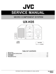
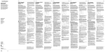
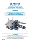
1
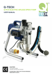
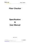
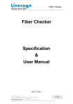
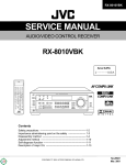
JC855 ARISTOPRAY USER MANUAL(AW)_Layout 1 07/03/2013 10:17 Page 1
Q-TECH
Q-P021 ELECTRIC AIRLESS SPRAY PUMP
Q-P025 ELECTRIC AIRLESS SPRAY PUMP
USER MANUAL
Aristospray UK
London
Granville House
Wallingford Road
Uxbridge
UB8 2RW
Dublin
2b Stephenstown
Industrial Park
Balbriggan
Co. Dublin
T 01895 276751
E [email protected]
T 00353 1690 3162
F 00353 1690 3480
E [email protected]
www.aristospray.com
CAUTION!
This manual contains
important warnings and information
PLEASE READ & KEEP FOR FUTURE REFERENCE
ISSUE DATE 31.01.2013
JC855 ARISTOPRAY USER MANUAL(AW)_Layout 1 07/03/2013 10:17 Page 3
3
User Manual Q-Tech Q-P021 / Q-P025 - Electric Airless Spray Pump
SPECIFICATIONS
Models
Motor Type
Max Pressure
Max Output
Max Tip Size
Q-P021
1000W TEFC DC
207 bar, 3000 PSI
2.1 l/min (0.55 gpm)
.021"
Material Applications
Wood interior
Ceiling
Wood exterior
Masonry
Structural steel
www.aristospray.com
SPECIFICATIONS
Models
Motor Type
Max Pressure
Max Output
Max Tip Size
Q-P025
1300W TEFC DC
207 bar, 3000 PSI
2.7 l/min (0.71 gpm)
.025"
Material Applications
lacquer, varnish, stain, sealer, enamel,
high-build,
exterior stain, vinyl, acrylic, latex,
alkyd, vinyl, latex, elastomeric, block filler,
heavy coatings
Wood interior
Ceiling
Wood exterior
Masonry
Structural steel
lacquer, varnish, stain, sealer, enamel,
high-build,
exterior stain, vinyl, acrylic, latex,
alkyd, vinyl, latex, elastomeric, block filler,
heavy coatings
Carry Handle
Filter Cap
Filter Cap
Manifold Filter
Pressure Control Knob
Manifold Filter
Packing Nut,
Pump Throat Oil
Priming Valve
Packing Nut,
Pump Throat
Fuse
Priming Valve
Pickup Tube
Drain Tube
Drain Tube
Suction Filter
On/Off
Switch
4
JC855 ARISTOPRAY USER MANUAL(AW)_Layout 1 07/03/2013 10:17 Page 5
5
User Manual Q-Tech Q-P021 / Q-P025 - Electric Airless Spray Pump
GENERAL SAFETY
RULES
WARNING! Read and understand all
instructions. Failure to follow all
instructions listed below may result in
electric shock, fire and / or serious
personal injury. The term airless sprayer in
all of the warnings listed below refers to
your mains-operated (corded) airless
sprayer.
SAVE THESE
INSTRUCTIONS
Work area
a) Keep your work area clean and well
lit. Cluttered benches and dark areas
invite accidents.
b) Do not operate airless sprayers in
explosive atmospheres, such as in
the presence of flammable liquid,
gases, or dust. Airless sprayers
create sparks which may ignite the
dust or fumes.
c) Keep bystanders, children, and
visitors away while operating a
airless sprayer. Distractions can
cause you to lose control.
Electrical Safety
a) Airless sprayer plugs must match
the outlet. Never modify the plug in
any way. Do not use any adapter
plugs with earthed (grounded)
airless sprayers. Unmodified plugs
and matching outlets will reduce the
risk of electric shock.
Grounded sprayers must be plugged
into an outlet properly installed and
grounded in accordance with all
codes and ordinances. Never
remove the grounding prong or
modify the plug in any way. Do not
b)
c)
d)
e)
use any adaptor plugs. Check with a
qualified electrician if you are in
doubt as to whether the outlet is
properly grounded. If the sprayer
should electrically malfunction or break
down, grounding provides a low
resistance path to carry electricity
away from the user.
Avoid body contact with grounded
surfaces such as pipes, radiators,
ranges and refrigerators. There is an
increased risk of electric shock if your
body is earthed or grounded.
Do not expose airless sprayers to
rain or wet conditions. Water entering
an airless sprayer will increase the risk
of electric shock.
Do not abuse the cord. Never use
the cord for carrying, pulling or
unplugging the airless sprayer. Keep
the cord away from heat, oil, sharp
edges or moving parts. Replace
damaged cords immediately.
Damaged or entangled cords increase
the risk of electric shock.
When operating an airless sprayer
outdoors, use an outdoor extension
cord suitable for outdoor use. Use of
a cord suitable for outdoor use
reduces the risk of electric shock.
Personal Safety
a) Stay alert, watch what you are doing
and use common sense when
operating an airless sprayer. Do not
use while you are tired or under the
influence of drugs, alcohol, or
medication. A moment of inattention
while operating airless sprayers may
result in serious personal injury.
b) Use safety equipment. Always wear
eye protection. Safety equipment
such as dust mask, non-skid safety
shoes, hard hat, or hearing protection
used for appropriate conditions will
reduce personal injuries.
www.aristospray.com
c) Avoid accidental starting. Ensure the
switch is in the off position before
plugging in.
d) Do not overreach. Keep a proper
footing and balance at all times. This
enables better control of the airless
sprayer in unexpected situations.
e) Dress properly. Do not wear loose
clothing or jewellery. Keep your hair,
clothing and gloves away from
moving parts. Loose clothes, jewellery
or long hair can be caught in moving
parts.
Service
Have your airless sprayer serviced by a
qualified repair person using only
identical replacement parts. This will
ensure that the safety of the airless
sprayer is maintained.
If the supply cord of this airless sprayer
is damaged it must be replaced by a
specially prepared cord available
through the service organization.
SPECIFIC SAFETY
RULES
HANDLE THIS UNIT AS YOU WOULD A
LOADED WEAPON!
Extreme high pressure spray can cause
extremely serious injury.
OBSERVE ALL WARNINGS!
WARNING: HIGH PRESSURE. Never
leave pressurized system unattended.
Always follow the Pressure Relief
Procedure. Take precautions to avoid high
pressure component rupture.
DANGER: INJECTION INJURY. Skin
injection by high pressure paint is not a
simple cut. It must be treated surgically
immediately.
WARNING: FIRE AND EXPLOSION
HAZARD. Take all precautions to avoid
sources of sparks and ignition when
spraying. Keep the machine at least 6
meters away from the spraying operation.
WEAR PROTECTIVE EQUIPMENT AT
ALL TIMES. Always use a respirator, eye
protection and protective clothing.
Keep clear of moving parts when starting
or operating the sprayer. Do not put your
fingers into any openings to avoid
amputation by moving parts or burns on
hot parts. When starting the motor,
maintain a safe distance from moving
parts of the equipment.
Before adjusting or servicing any
mechanical part of the sprayer, follow the
PRESSURE RELIEF PROCEDURE.
EXPLOSION RISK FROM
HALOGENATED HYDROCARBON
SOLVENTS
Never use halogenated hydrocarbon
solvents in this machine.
Contact with aluminum parts may cause
an explosion.
Some of the most common of these
solvents are:
Carbontetrachloride
Chlorobenzene
Dichloroethane
Dichloroethyl Ether
Ethylbromide
Ethylchloride
Tethrachloethane
6
JC855 ARISTOPRAY USER MANUAL(AW)_Layout 1 07/03/2013 10:17 Page 7
7
User Manual Q-Tech Q-P021 / Q-P025 - Electric Airless Spray Pump
PREVENT STATIC
SPARKING
FIRE/EXPLOSIONS
Vapors created when spraying can be
ignited by sparks.
To reduce the risk of fire, always locate the
sprayer at least 20 feet (6 m.) away from
spray area. Do not plug in or unplug any
electrical cords in the spray area. Doing so
can cause sparks which can ignite any
vapors still in the air. Follow the coating &
solvent manufacturers safety warnings
and precautions.
MEDICAL ALERT - Airless Spray
Injection Injuries
If any fluid appears to penetrate your skin,
GET EMERGENCY MEDICAL CARE AT
ONCE.
DO NOT TREAT AS AN ORDINARY CUT.
High pressure fluids from spray or leaks
are powerful enough to easily penetrate
the skin and cause extremely serious
injection injury, leading to the possible
need for amputation.
• NEVER point the spray gun at anyone
or any part of the body.
• NEVER put your hand or fingers over
the spray tip. Do not use a rag or any
other materials over your fingers. Paint
will penetrate through these materials
and into the hand.
• NEVER try to stop or deflect leaks with
your hand or body.
• ALWAYS have the tip guard in place
when spraying.
•
•
•
•
•
•
•
•
•
•
•
•
•
ALWAYS lock the gun trigger when
you stop spraying.
ALWAYS remove tip from the gun to
clean it.
NEVER try to "blow back" paint, this is
not an air powered sprayer.
ALWAYS follow the PRESSURE
RELIEF PROCEDURE before cleaning
or removing the spray tip or servicing
any system equipment.
Be sure the equipment safety devices
are operating properly before each use.
Tighten all of the fluid connections
before each use.
NEVER alter equipment in any manner.
NEVER smoke while in spraying area.
NEVER spray highly flammable
materials.
NEVER use around children.
NEVER allow another person to use
sprayer unless he is thoroughly
instructed on its safe use and given
this operator’s manual to read.
ALWAYS wear a spray mask, gloves
and protective eye wear while
spraying.
ALWAYS ensure fire extinguishing
equipment is readily available and
properly maintained.
NEVER LEAVE SPRAYER UNATTENDED
WITH PRESSURE IN THE SYSTEM.
FOLLOW PRESSURE RELIEF
PROCEDURES
www.aristospray.com
•
•
•
•
Keep the spraying area free from
obstructions.
Make sure the spraying area has good
ventilation to safely remove vapors and
mists.
NEVER keep flammable material in
spraying area.
TOXIC FLUID
HAZARD
•
SPRAY GUN SAFETY
•
•
•
•
•
ALWAYS set gun safety lock in the
"LOCKED" position when not in use &
before servicing or cleaning.
NEVER remove or modify any part of
the gun.
ALWAYS REMOVE THE SPRAY TIP
when cleaning. Flush unit at the
LOWEST POSSIBLE PRESSURE.
ALWAYS check operation of all gun
safety devices before each use.
Be very careful when removing the
spray tip or hose from the gun. A
plugged line will contain fluid under
pressure. If the tip or line is plugged,
follow the pressure relief procedure
TIP GUARD
•
ALWAYS have the tip guard in place
on the spray gun while spraying. The
tip guard alerts you to the injection
hazard and helps prevent accidentally
placing your fingers or any part of your
body close to the spray tip.
•
•
•
•
Use extreme caution when cleaning or
changing spray tips. If the spray tip
clogs while spraying, engage the gun
safety latch immediately. ALWAYS
follow the PRESSURE RELIEF
PROCEDURE and then remove the
spray tip to clean it.
NEVER wipe off build up around the
spray tip.
ALWAYS remove tip guard & tip to
clean AFTER pump is turned off and
the pressure is relieved by following
the PRESSURE RELIEF
PROCEDURE.
Hazardous fluid or toxic fumes can
cause serious injury or death if
splashed in eyes or on skin, inhaled or
swallowed. Know the hazards of the
fluid you are using. Store & dispose of
hazardous fluid according to
manufacturer, local, state & national
guidelines.
ALWAYS wear protective eyewear,
gloves, clothing and respirator as
recommended by fluid manufacturer.
HOSES
•
•
SPRAY TIP SAFETY
ALWAYS INSPECT
SPRAYING AREA
•
NEVER spray in vicinity of open flame
or other sources of ignition.
The spraying area must be at least 20
ft. away from spray unit.
•
Tighten all of the fluid connections
securely before each use. High
pressure fluid can dislodge a loose
coupling or allow high pressure spray
to be emitted from the coupling and
result in an injection injury or serious
bodily injury.
Only use hoses with a spring guard.
The spring guard helps protect the
hose from kinks or other damage
which could result in hose rupture and
cause an injection injury. Do not allow
kinking or crushing of hoses or allow it
to vibrate against rough, sharp or hot
surfaces.
Use only conductive fluid hoses for
airless applications. Be sure the gun is
grounded through the hose
connections. Use only high pressure
airless hoses with static wire which are
approved for 3000 psi.
8
JC855 ARISTOPRAY USER MANUAL(AW)_Layout 1 07/03/2013 10:17 Page 9
9
User Manual Q-Tech Q-P021 / Q-P025 - Electric Airless Spray Pump
•
•
NEVER use a damaged hose, which
can result in hose failure or rupture and
cause an injection injury or other
serious bodily injury or property
damage. Before each use, check entire
hose for cuts, leaks, abrasions, bulging
of the cover, or damage or movement
of couplings. If any of these conditions
exist, replace the hose immediately.
NEVER use tape or any device to try to
mend the hose as it cannot contain the
high pressure fluid. NEVER ATTEMPT
TO RECOUPLE THE HOSE. A high
pressure hose is not possible to
recouple.
GROUNDING
•
•
Ground the sprayer & other
components in the system to reduce
the risk of static sparking, fire or
explosion which can result in serious
bodily injury and property damage. For
detailed instructions on how to ground,
check your local electrical code.
ALWAYS ensure switch is in OFF
position before plugging unit in.
Always Ground All of These
Components:
1. Sprayer: plug the power supply cord,
or extension cord, each equipped with
an undamaged three-prong plug, into a
properly grounded outlet. DO NOT
USE AN ADAPTER. Use only a 3 wire
extension cord that has a grounding
plug, and a receptacle that will accept
the grounding plug on the product.
Make sure your extension cord is in
good condition. When using an
extension cord, be sure to use one
heavy enough to carry the current your
product will draw. If in doubt, use the
next heavier gauge.
2. Fluid hose: use only grounded hoses.
3. Spray gun or dispensing valve:
grounding is obtained through
connection to a properly grounded
fluid hose and pump.
4. All solvent pails must be conductive
metal material and properly
grounded. Do not place on a non
conductive insulating surface unless
a ground wire is added to a true
earth such as a metal water pipe.
ALWAYS ensure fire extinguishing
equipment is readily available and
properly maintained.
FLUSHING SAFETY
WHEN SPRAYING & CLEANING WITH
FLAMMABLE PAINTS AND THINNERS
1. When spraying with flammable liquids,
the unit must be located a minimum of
25 feet away from the spraying area in
a well ventilated area. Ventilation must
be sufficient enough to prevent the
accumulation of vapors.
2. To eliminate electrostatic discharge,
ground the spray unit, paint bucket &
spraying object. See GROUNDING.
Use only high pressure airless hoses
approved for 3000 psi which is
conductive.
3. Remove the spray tip before flushing.
Hold the metal part of the gun firmly to
the side of a metal pail & use the
lowest possible fluid pressure during
flushing.
4. Never use high pressure in the cleaning
process. USE MINIMUM PRESSURE.
5. Do not smoke in spraying/cleaning
area.
• NEVER use cleaning solvents with
flash points below 140 degrees F.
Some of these are: acetone, benzene,
ether, gasoline, naptha. Consult your
supplier to be sure.
www.aristospray.com
ASSEMBLY:
1. Attach the hose to the pump and
tighten with a wrench.
2. Attach the hose to the gun and tighten
with a wrench.
OPERATION
BEFORE BEGINNING:
1. New Sprayer
Your sprayer was factory tested in an
oil solution which was left in the pump.
Before using oil-base paint, flush with
pump conditioner only.
Before using water-base paint flush
with pump conditioner, followed by
soapy water, then a clean water flush.
2. Changing Colors
Flush with a compatible solvent such
as pump conditioner or water.
3. Changing from water-base to oilbase paint.
Flush with soapy water, then pump
conditioner.
PRESSURE RELIEF
PROCEDURE
IMPORTANT! To avoid possible serious
body injury, always follow this
Gun safety
latch
Gun Trigger
procedure whenever the sprayer is shut
off, when checking it, when installing,
changing or cleaning tips and whenever
you stop spraying.
1. Engage the gun safety latch.
2. Turn the unit off & unplug it from the
electrical outlet.
3. Disengage the gun safety latch and
trigger the gun to relieve residual fluid
pressure. Hold metal part of the gun in
contact with grounded metal pail.
4. Turn the Priming Valve to the open
(priming) position to relieve residual
fluid pressure.
5. Re-engage gun safety latch and close
Priming Valve.
If the SPRAY TIP OR HOSE IS
CLOGGED, follow Step 1 through 5
above. Expect paint splashing into the
bucket while relieving pressure during
Step 4.
FLUSHING
When to flush:
1. Cleanup (for further instructions see
“cleanup” below)
2. Changing from oil-base to waterbase paint.
Flush with pump conditioner, followed
by soapy water, then a clean water
flush.
3. Storage
Always relieve pressure (See pressure
relief procedure above) prior to storage
or when machine is unattended.
Oil-base Paint: Flush with pump
conditioner. Ensure that there is no
pressure in the unit, then close the
priming valve.
Water-base Paint: Flush with water,
then pump conditioner. For longer term
storage fill with pump conditioner.
Always ensure that there is no pressure
in the unit, and close the
prime/pressure relief valve for storage.
10
JC855 ARISTOPRAY USER MANUAL(AW)_Layout 1 07/03/2013 10:17 Page 11
11
User Manual Q-Tech Q-P021 / Q-P025 - Electric Airless Spray Pump
4. Start-up after storage
Before using water-base paint, flush
with soapy water and then with clean
water.
When using oil-base paint, flush out
the pump conditioner with the material
to be sprayed.
How to Flush:
1. Be sure the gun safety latch is
engaged and there is no spray tip in
the gun.
2. Pour enough clean, compatible solvent
into a large, empty metal pail to fill the
pump and hoses.
3. Place the suction tube into the pail.
4. Turn the Priming Valve to the "OPEN",
priming position.
5. Point the gun into the metal pail and
hold a metal part of the gun firmly
against the pail.
To reduce the risk of static sparking
which can cause fire or explosion,
always hold a metal part of the gun
firmly against the metal pail when
flushing. This also reduces
splashing.
Disengage the gun safety latch and
squeeze the gun trigger. Turn the ONOFF Toggle Switch to the "ON"
position and turn Pressure Control
Knob clockwise to increase pressure
just enough to start the pump.
7. Close the priming valve. This will allow
solvent to be flushed through the
pump, hoses and gun. Allow the unit to
operate until clean solvent comes from
the gun.
8. Release the trigger and engage the
gun safety latch.
9. Whenever you shut off the sprayer,
follow the "PRESSURE RELIEF
PROCEDURE".
www.aristospray.com
SPRAYING
1. Connect the hose and gun.
2. Check the electrical service.
Be sure the electrical service matches
the rating on the machine’s nameplate
and that the outlet you use is properly
grounded.
3. Fill the packing nut/wet cup with a
few drops of Q-Lube Piston
Lubricant.
4. Flush the sprayer
a. Prepare the media to be sprayed
according to the material
manufacturer's recommendations.
b. Place the suction tube into the
media container.
c. Prime Valve must be "OPEN" in the
priming position.
d. When you have ensured that the
gun safety latch is engaged, attach
tip and safety guard.
e. Turn the power switch to the "ON"
position.
f. Allow the pump to prime. After the
pump is primed, immediately turn
Prime Valve to the "Closed"
position.
g. Turn Pressure Control Knob to the
desired spray pressure.
h. Disengage the gun safety latch and
you are ready to spray.
Pressure Control Knob
On/Off Switch
Spraying, Adjusting the pressure
a. Turn the Pressure Control Knob
Clockwise to increase pressure and
counterclockwise to decrease
pressure.
b. Always use the lowest pressure
necessary to completely atomize the
material.
Note: Operating the sprayer at higher
pressure than needed, wastes material,
causes early tip wear, and shortens
sprayer life. It will also result in the
motor cycling on and off to maintain
pressure. This cycling will result in poor
and inconsistent spraying results.
c. If more coverage is needed, use a
larger tip rather than increasing the
pressure.
d. Check the spray pattern. The tip size
and angle determines the pattern width
and flow rate. Spray a test pattern and
then adjust the pressure to eliminate
heavy edges. Use a smaller tip size if
the pressure adjustment can not
eliminate heavy edges.
e. While spraying, hold the gun
perpendicular, about 25-30cm (10-12
inches) away from the surface. Spray
back and forth. Trigger the gun before
moving and release the trigger after
each stroke. Overlap by 50%.
WARNING: When you spray into the
paint bucket, always use the lowest
spray pressure and maintain firm metal
to metal contact between gun and
container. To stop the unit in an
emergency, turn the motor off. Then
relieve the fluid pressure in the pump
and hose as instructed in the Pressure
Relief Procedure.
WARNING: Follow the "Pressure Relief
Procedure". To reduce the risk of
injection, never hold your hand, body,
fingers or hand in a rag in front of the
spray tip when cleaning or checking for
a cleared tip. Always point the gun
toward the ground or into a waste
container when checking to see if the
tip is cleared or when using a selfcleaning tip.
5. When Shutting off the Sprayer
a. Whenever you stop spraying, even
for a short break, follow the
"Pressure Relief Procedure".
b. Flush the sprayer at the end of
each work day, if the material you
are spraying is water-based, or if it
could harden in the sprayer
overnight. See "Flushing". Use a
compatible solvent to flush, then fill
12
JC855 ARISTOPRAY USER MANUAL(AW)_Layout 1 07/03/2013 10:17 Page 13
13
User Manual Q-Tech Q-P021 / Q-P025 - Electric Airless Spray Pump
the pump and hoses with an oil
based solvent such as pump
conditioner.
SPRAY GUN
Attach spray gun to airless unit and tighten
fittings securely. Set the gun safety latch.
The gun safety latch should always be set
when the gun is not being triggered.
Read all warnings and safety precautions
supplied with the spray gun and in product
manual.
Tip
TO REMOVE CLOGS FROM SPRAY TIP
1. Lock gun safety latch.
2. Turn Tip handle 180 degrees.
3. Disengage trigger lock & trigger gun
into pail.
4. If the Tip handle appears locked
loosen the retaining nut. The handle
will now turn easily.
5. Engage gun safety latch & return
handle to the spray position.
CLEANING
SPRAY GUN
CLEANING FILTER IN GUN
HANDLE
Seat
Tip Guard
Gasket
SPRAY TIP
ASSEMBLY
1. Be sure pressure relief procedure is
followed before assembling tip and
housing to the gun.
2. Lock gun safety latch.
3. Insert Tip into the guard housing
assembly.
4. Guide metal seat into guard housing
assembly through retaining nut & turn
until it seats against the cylinder.
5. Insert O-Ring gasket on metal seat so
it fits in the grooves.
6. Finger tighten guard housing retaining
nut onto the gun.
7. Turn guard in the desired position.
8. Completely tighten the retaining nut.
Immediately after the work is finished,
flush the gun out with a solvent. Brush
pins with solvent and oil them lightly so
they will not collect dried paint. To clean
the filter, use a brush dipped in an
appropriate solvent. Change or clean
filters at least once a day. Some types of
latex may require a filter change after
About four hours of operation.
CLOGGED FLAT TIP
Should the spray tip become clogged,
relieve pressure from hose by following the
"Pressure Relief Procedure." Secure gun
with the safety latch, take off guard, take
out the tip, soak in appropriate solvent &
clean with a brush. (Do not use a needle or
sharp pointed instrument to clean the tip.
The tungsten carbide is brittle and can
chip.)
SPRAY TIP SELECTION
Spray tip selection is based on paint
viscosity, paint type, and job needs.
Generally, use a smaller tip For light
viscosities (thin paints), and use a larger
tip for heavier viscosities (thicker paints).
Spray tip size is based on how many
www.aristospray.com
gallons of paint per minute can be sprayed
through the tip. Do not use a tip larger
than the maximum pump flow rate or
capacity the sprayer can accommodate.
Pump flow rate is measured in gallons per
minute (GPM) and liters per minute (LPM).
PATTERN WIDTH
Two tips having the same tip size, but
different pattern widths will deliver the
same amount of paint over a different area
(wider or narrower strip). A spray tip with a
narrow pattern width makes it easy to
spray in tight places. Thickness of the
paint coat per stroke is determined by
spray tip "fan width", rate of the spray gun
movement, and distance to surface.
5. Move the gun to a waste pail. While
holding the gun against the pail, trigger
the gun to thoroughly flush the system.
Release the trigger and put the trigger
safety on.
6. Open the priming valve and allow the
flushing fluid to circulate for 15
seconds (to clean the drain tube).
7. Raise the pickup tube out of the
flushing fluid and run the sprayer for
20-30 seconds to drain the fluid.
8. Close the priming valve. Trigger the
gun into flushing pail to purge the
hose.
SPRAY TIP REPLACEMENT
During use, especially with latex paint,
high pressure will cause the orifice to grow
larger. This destroys the pattern.
Replace tips before they become
excessively worn. Worn tips waste paint,
cause overspray, make cutting-in difficult,
and decrease sprayer performance.
If the tip is the maximum rated size, when
it wears, it will exceed the flow rate
capacity of the sprayer. If when using
maximum capacity tip size the pump
cannot keep up, then you know that the
tip is worn beyond capacity.
CLEANUP
1. Perform pressure relief procedure.
2. Place pickup tube in a bucket of
flushing fluid. (Use water for water
base paint and pump conditioner for oil
base paint).
3. Turn the power on. Close priming
valve.
4. Increase pressure to half. Hold the gun
against the paint pail. Take off the
trigger safety. Trigger the gun until
flushing fluid appears.
Pump
Filter
Gun
Filter
9. Turn the power off.
10. Open the priming valve.
11. Unplug the sprayer.
12. Remove the filters from the pump and
gun. Clean and replace.
13. If flushing was with water, flush again
with pump conditioner to prevent
corrosion inside the pump. (for long
term storage, mix motor oil into the
spirits).
14. Clean the exterior of the sprayer with
rag soaked in pump conditioner.
14
JC855 ARISTOPRAY USER MANUAL(AW)_Layout 1 07/03/2013 10:17 Page 15
15
User Manual Q-Tech Q-P021 / Q-P025 - Electric Airless Spray Pump
DAILY MAINTENANCE
1. Keep the displacement pump packing
nut/wet cup lubricated with Q-Lube
Piston Lubricant at all times. Add
about five drops of oil to the top of the
pump each day. This helps protect the
rod and the packings.
2. Inspect the packing nut daily. If
seepage of paint into the packing nut
and/or movement of the piston upward
is found (while not spraying), the
packing nut should be tightened
enough to stop leakage only, but not
any tighter. Overtightening will damage
the packings and reduce the packing
life.
PUMP PACKINGS
The packings are a wearing part. If the
pump can no longer maintain pressure,
has difficulty priming and paint seeps into
the throat of the pump, and tightening the
packing nut no longer helps, then the
packings will require replacement. This is
best entrusted to a qualified repair
technician.
To remove the pump and replace the
packings, follow the instructions below:
PUMP REMOVAL:
1. Use the special spline wrench to
loosen the gland nut (2) and remove
the pickup tube (3) from the bottom of
the pump. At the same time remove
the inlet ball seat disc (5), o-ring (6),
check ball (7) and ball guide (8)
2. Lay the machine on its back and
remove the heat sink electronics unit
(67). This will allow access to unplug
the pressure sensor (12) from the
electronics unit.
3. Disconnect the junction (42) and three
screws (40) on the pump filter bracket
and remove the pump filter.
4. Turn the pump until the piston is at its
lowest point. This will allow the snap
ring (33) to be removed. This in turn will
allow you to push out the piston wrist
pin (35).
5. Remove the four bolts (9) to take off
the pump unit.
6. Replacement is the reverse of removal.
Grease the exposed portion of the
piston and wrist pin when assembling.
www.aristospray.com
When the brushes are worn to a length of
1/4", they should be replaced.
TO CHANGE THE BRUSHES
1. Unplug the machine.
PACKINGS REPLACEMENT:
1. Loosen the packing nut with the
special wrench supplied and remove.
2. Pull out the piston.
3. Remove all parts and clean. Clamp the
piston and in the bottom of the piston,
remove the socket set screw (22) to
allow removal of the small ball seat
(23), and check ball (24)
4. Discard all old packings.
5. Soak the new leather packings in W30
oil for at least one hour before
assembling.
6. Replace the packings, glands, o-rings
and check balls with the new parts
from the rebuild kit. Strictly follow the
exact order and orientation.
7. Replace piston and thread on the
packing nut. After resistance from the
disc springs is felt, tighten the packing
nut a further 3/4 turn.
MOTOR
MAINTENANCE
LUBRICATION – The gear case grease
may be changed every 200 hours of
operation. This is best entrusted to a
qualified repair technician.
THE CARBON BRUSHES-The carbon
brushes are a normal wearing part and
must be replaced when they reach their
wear limit.
Brush
Cap
2. Remove the brush cap with a slothead
screwdriver
3. Remove the brush.
4. Install new brushes in reverse order
and replace covers
16
JC855 ARISTOPRAY USER MANUAL(AW)_Layout 1 07/03/2013 10:17 Page 17
17
User Manual Q-Tech Q-P021 / Q-P025 - Electric Airless Spray Pump
www.aristospray.com
TROUBLESHOOTING
Problem: Motor will not run
Problem:Low output
Check
Solution
Check
Solution
Electrical supply- must match voltage
on machine nameplate
Use correct outlet
Worn tip
Relieve pressure and replace tip
Worn packings
Replace packings
Extension cord-check continuity
Replace extension
Filter clogged
Relieve pressure and Clean filter
Power supply cable-check continuity
Replace cable
Priming valve leaking
Relieve pressure and repair valve
Carbon brushes
Replace brushes
Suction pipe leaking or kinked
Correct kink, or tighten as needed
Bad switch
Replace switch
Low voltage
Use shorter extension cord
Motor damage
Replace or repair motor
Pump runs on when trigger is released
Service pump
Problem: Pump loses prime or will not prime
Check
Solution
Low paint
Refill
Clogged inlet strainer
Clean
Loose suction pipe
Tighten connection
Intake ball not seating
Clean or replace
Problem: Motor cannot turn pump
Check
Solution
Paint hardened in pump
Replace packings
Paint frozen in pump
Thaw pump
Problem: Pressure problems
Check
Solution
Clogged tip or filter
Relieve pressure and clean
Problem: Motor cannot maintain pressure
Check
Solution
Oversized tip
Use correct tip for sprayer
Tip worn to become oversize
Relieve pressure and replace tip
Problem: Motor runs intermittently
Check
Solution
Pressure set too high for the tip size
Adjust to the correct pressure
Problem: Motor hot and overloaded
Check
Solution
Packings too tight
Properly adjust packing nut
18
JC855 ARISTOPRAY USER MANUAL(AW)_Layout 1 07/03/2013 10:17 Page 19
19
User Manual Q-Tech Q-P021 / Q-P025 - Electric Airless Spray Pump
www.aristospray.com
QP025 EXPLODED VIEW
48
103
49
70
89
47
94
46A
46B
46C
40
101
93
41
45
75
35
FOR 1300W
52 MOTOR
34
55
33
43
32
42
53
31
20
50
08
51
04
99
45
11
03B
03A
10
02
01
09
90
62
23
98
22
13
14
72
64
68
1300W
67-1 FOR
MOTOR-110V
67-2
83
109
63
25
07
74
60
110
95
86
61
21
104
45
81
75
79
76
59
58
111
12
77
FOR 1300W
MOTOR-220V
87
80
96
57
05
56
78
87
97
112
30
108
91
36
39
102
88
86
1300W
54-2 FOR
MOTOR-220V
37
44
92
1300W
54-1 FOR
MOTOR-110V
38
11
90
75
65
66
75
74
73
69
72
74
82
85
71
84
85
72
NO.01~112 V3.5
75
75
20
JC855 ARISTOPRAY USER MANUAL(AW)_Layout 1 07/03/2013 10:17 Page 21
21
User Manual Q-Tech Q-P021 / Q-P025 - Electric Airless Spray Pump
www.aristospray.com
QP025 PARTS LIST
Q-TECH PART NO.
QF0535015B
QP00002
QP00003A
QP00003B
QP00004
QP00005
QP00006
INCL. IN KIT 1
QP00008
QP00009
QP00010
QP00011
QP00012
QP00013
QP00014
QP00020
QP00021
INCL. IN KIT 2
INCL. IN KIT 2
INCL. IN KIT 2
QP00030
QP00031
QP00032
QP00033
QP00034
QP00035
QP00036
QP00037
QP00038
QP00039
QP00040
QP00041
QP00042
QP00043
QP00044
QP00045
QF0571xxx
QP00047
QP00048
ITEM
1
2
3A
3B
4
5
6
7
8
9
10
11
12
13
14
20
21
22
23
25
30
31
32
33
34
35
36
37
38
39
40
41
42
43
44
45
46
47
48
DESCRIPTION
INLET STRAINER
GLAND NUT
SUCTION TUBE
SUCTION HOSE
O-RING Ø2 x Ø15.9 x Ø19.9
INTAKE DISC
O-RING 3028
CHECK BALL & PISTON PACKING
BALL GUIDE
SOCKET CAP SCREW
M8 x 25
PUMP HOUSING
OUTPUT NIPPLE PT 1/4" x 1/4"-19UNF
PRESSURE TRANSDUCER
PRIMING VALVE
DRAIN TUBE
PT1/8" x 0.45M
PACKING SPACER
DISC SPRING
BALL SEAT FASTENER
M16 x P1.0
BALL SEAT-SMALL
Ø4 x Ø13.8 x 4
DISPLACEMENT PISTON
O-RING
S-31.5
SEAL SEAT
PACKING NUT
SNAP RING
WRIST PIN-ROD Ø16 x 32
WRIST PIN-PISTON
Ø9.5 x 25
DRIVE PISTON
SCREW
M5 x 8
GUIDE CYLINDER
Ø38 x Ø44 x 43
SOCKET CAP SCREW
M8 x 50
SCREW
M8 x 16
L-BRACKET
FITTING
PT 1/4"-19 x 1/4"-19UNF
FILTER HOUSING
BRACKET
SCREW
M5 x 8
PUMP FILTER AVAILABLE IN 30,60,100,200 MESH
FILTER CAP
CRANK HOUSING
Kit 1. Complete Packing Kit: QP00016 Kit 2. Complete Piston Rod Assy: QP00025
QP025 PARTS LIST
QTY
1
1
1
1
1
1
1
1
1
4
1
2
1
1
1
1
3
1
1
1
2
1
1
1
1
1
1
2
1
4
2
1
1
1
1
7
1
1
1
Q-TECH PART NO.
QP00049
QP00050
QP00051
QP00052
QP00053
QP00054-1
QP00054-2
QP00055
QP00056
QP00057
QP00058
QP00059
QP00060
QP00061
QP00062
QP00063
QP00064
QP00065
QP00066
QP00067-1
QP00067-2
QP00068
QP00069
614154TD
ITEM
49
50
51
52
53
54-1
54-2
55
56
57
58
59
60
61
62
63
64
65
66
67-1
67-2
68
69
70
QP00071
QP00072
QP00073
QP00074
QP00075
QP00076
QP00077
QP00078
QP00079
QP00080
QP00081
QP00082
QP00083
QP00084
71
72
73
74
75
76
77
78
79
80
81
82
83
84
DESCRIPTION
BALL BEARING 6004 zz
CONNECTING ROD
NEEDLE BEARING
HK 3012
CRANK GEAR
DP24 x 121T (1300W)
BALL BEARING 6301 zz
MOTOR UNIT
1300W (110V)
MOTOR UNIT
1300W (220V)
CARBON BRUSH8 x 16
BRUSH CAP
CONTROL BOX
PRESSURE ADJUSTOR
SET SCREW
M4 x 4
ADJUSTOR WHEEL
POWER SWITCH
FUSE
NUT
M3
LCD DISPLAY
WINDOW
SCREW
M3 x 12
ELECTRONICS UNIT
1300W (110V)
ELECTRONICS UNIT
1300W (220V)
SOCKET CAP SCREW
M4 x 12
POWER SUPPLY CORD 1.5 x 3C x 3.5M
HIGH PRESSURE HOSE 16.5M 3300 PSI
1/4"-19UNF
END CAP
FRAME BRACKET-LOWER
FRAME
FRAME BRACKET-UPPER
SCREW
M5 x 32
CROSSPIECE-FRONT
SOCKET CAP SCREW
M6 x 16
RELEASE LEVER
CROSSPIECE-REAR
SPRING
Ø1 x Ø13 x Ø15 x 10T x 70L
RELEASE BUTTON
CROSSBAR
LOWER HOSE BRACKET
WHEEL
Kit 1. Complete Packing Kit: QP00016 Kit 2. Complete Piston Rod Assy: QP00025
QTY
1
1
1
1
1
1
1
2
2
1
1
1
1
1
1
2
1
1
2
1
1
4
1
1
2
4
1
4
28
1
2
2
1
1
1
1
1
2
22
JC855 ARISTOPRAY USER MANUAL(AW)_Layout 1 07/03/2013 10:17 Page 23
User Manual Q-Tech Q-P021 / Q-P025 - Electric Airless Spray Pump
www.aristospray.com
100
77
91
89
69
66
62
FOR 1000W
MOTOR-220V
68
13
23
22
25
45
104
21
09
10
11
45
03B
04
05
111
08
43
01
102
108
45
44
11
46A
46B
46C
42
20
40
39
101
99
90
41
12
30
31
32
33
34
14
98
112
35
36
37
38
07
95
57
67A-2
63
51
50
FOR 1000W
52A MOTOR
1000W
67A-1 FOR
MOTOR-110V
64
65
110
61
60
59
96
58
53
97
FOR 1000W
54A-1 MOTOR-110V
FOR 1000W
54A-2 MOTOR-220V
109
93
55
56
107
71
94
90
92
106
NO.01~112 V3.5
105
QP021 EXPLODED VIEW
QTY
4
2
2
1
1
2
1
2
1
1
5
1
1
1
2
2
2
1
1
2
1
2
1
47
DESCRIPTION
CIRCLIP
S-19
HANDLE SLIDE BRACKET B
HANDLE SLIDE BRACKET A
HANDLE
TOOL BOX LID
HAND KNOB
M5 x 8
TOOL BOX
SOCKET CAP SCREW
M6 x 35
DUAL PURPOSE WRENCH
SCREW
M5 x 12
SCREW
M4 x 10
CABLE GLAND SB7R-3
CABLE GLAND SB8R-3
O-RING 2009
FENCE
FLAT WASHER Ø8 x Ø19 x 3
TUBE HOLDER Ø12.5 x Ø22.5
LUBRICATING OIL TANK 100 cc
L-ATTACHMENT
TUBE HOLDER Ø12.5 x Ø28
FUSE PLATE
WIRE
WASHER Ø28.5 x Ø36 x 3
103
ITEM
85
86
87
88
89
90
91
92
93
94
95
96
97
98
99
101
102
103
104
108
109
110
111
70
Q-TECH PART NO.
QP00085
QP00086
QP00087
QP00088
QP00089
QP00090
QP00091
QP00092
QP00093
QP00094
QP00095
QP00096
QP00097
INCL. IN KIT 1
QP00099
QP00101
QP00102
QP00103
QP00104
QP00108
QP00109
QP00110
QP00111
49
QP025 PARTS LIST
48
23
24
JC855 ARISTOPRAY USER MANUAL(AW)_Layout 1 07/03/2013 10:17 Page 25
25
User Manual Q-Tech Q-P021 / Q-P025 - Electric Airless Spray Pump
www.aristospray.com
QP021 PARTS LIST
Q-TECH PART NO.
QF0535015B
QP00002
QP00003B
QP00004
QP00005
QP00006
INCL. IN KIT 1
QP00008
QP00009
QP00010
QP00011
QP00012
QP00013
QP00014A
QP00020
QP00021
INCL. IN KIT 2
INCL. IN KIT 2
INCL. IN KIT 2
QP00030
QP00031
QP00032
QP00033
QP00034
QP00035
QP00036
QP00037
QP00038
QP00039
QP00040
QP00041A
QP00042
QP00043
QP00044
QP00045
QF0571xxx
QP00047
QP00048
ITEM
1
2
3B
4
5
6
7
8
9
10
11
12
13
14A
20
21
22
23
25
30
31
32
33
34
35
36
37
38
39
40
41A
42
43
44
45
46
47
48
DESCRIPTION
INLET STRAINER
GLAND NUT
SUCTION HOSE
O-RING
Ø2 x Ø15.9 x Ø19.9
INTAKE DISC
O-RING
3028
CHECK BALL & PISTON PACKING
BALL GUIDE
SOCKET CAP SCREW
M8 x 25
PUMP HOUSING
OUTPUT NIPPLE PT 1/4" x 1/4"-19UNF
PRESSURE TRANSDUCER
PRIMING VALVE
DRAIN TUBE
PT1/8" x 1.28M
PACKING SPACER
DISC SPRING
BALL SEAT FASTENER
M16 x P1.0
BALL SEAT-SMALL
Ø4 x Ø13.8 x 4
DISPLACEMENT PISTON
O-RING
S-31.5
SEAL SEAT
PACKING NUT
SNAP RING
WRIST PIN-ROD Ø16 x 32
WRIST PIN-PISTON
Ø9.5 x 25
DRIVE PISTON
SCREW
M5 x 8
GUIDE CYLINDER
Ø38 x Ø44 x 43
SOCKET CAP SCREW
M8 x 50
SCREW
M8 x 16
L-BRACKET
FITTING
PT 1/4"-19 x 1/4"-19UNF
FILTER HOUSING
BRACKET
SCREW M5 x 8
PUMP FILTER AVAILABLE IN 30,60,100,200 MESH
FILTER CAP
CRANK HOUSING
Kit 1. Complete Packing Kit: QP00016 Kit 2. Complete Piston Rod Assy: QP00025
QP021 PARTS LIST
QTY
1
1
1
1
1
1
1
1
4
1
2
1
1
1
1
3
1
1
1
2
1
1
1
1
1
1
2
1
4
2
1
1
1
1
7
1
1
1
Q-TECH PART NO.
QP00049
QP00050
QP00051
QP00052A
QP00053
QP00054-A1
QP00054-A2
QP00055
QP00056
QP00057
QP00058
QP00059
QP00060
QP00061
QP00062
QP00063
QP00064
QP00065
QP00066
QP00067-A1
QP00067-A2
QP00068
QP00069
QP00070
ITEM
49
50
51
52A
53
54-A
54-A2
55
56
57
58
59
60
61
62
63
64
65
66
67-A1
67-A2
68
69
70
QP00071
QP00077
QP00089
QP00090
QP00091
QP00092
QP00093
QP00094
QP00095
QP00096
QP00097
INCL. IN KIT 1
QP00099
71
77
89
90
91
92
93
94
95
96
97
98
99
DESCRIPTION
BALL BEARING 6004 zz
CONNECTING ROD
NEEDLE BEARING
HK 3012
CRANK GEAR
DP24 x 121T (1000W)
BALL BEARING 6301 zz
MOTOR UNIT
1000W (110V)
MOTOR UNIT
1000W (220V)
CARBON BRUSH 8 x 16
BRUSH CAP
CONTROL BOX
PRESSURE ADJUSTOR
SET SCREW
M4 x 4
ADJUSTOR WHEEL
POWER SWITCH
FUSE
NUT M3
LCD DISPLAY
WINDOW
SCREW
M3 x 12
ELECTRONICS UNIT
1000W (110V)
ELECTRONICS UNIT
1000W (220V)
SOCKET CAP SCREW
M4 x 12
POWER SUPPLY CORD 1.5 x 3C x 3.5M
HIGH PRESSURE HOSE 16.5M 3300 PSI
1/4"-19UNF
END CAP
SOCKET CAP SCREW
M6 x 16
TOOL BOX LID
HAND KNOB
M5 x 8
TOOL BOX
SOCKET CAP SCREW
M6 x 35
DUAL PURPOSE WRENCH
SCREW
M5 x 12
SCREW
M4 x 10
CABLE GLAND SB7R-3
CABLE GLAND SB8R-3
O-RING
2009
FENCE
Kit 1. Complete Packing Kit: QP00016 Kit 2. Complete Piston Rod Assy: QP00025
QTY
1
1
1
1
1
1
1
2
2
1
1
1
1
1
1
2
1
1
2
1
1
4
1
1
2
2
1
2
1
2
1
1
5
1
1
1
2
26
JC855 ARISTOPRAY USER MANUAL(AW)_Layout 1 07/03/2013 10:17 Page 27
27
User Manual Q-Tech Q-P021 / Q-P025 - Electric Airless Spray Pump
www.aristospray.com
QP021 PARTS LIST
Q-TECH PART NO.
QP00100
QP00101
QP00102
QP00103
QP00104
QP00105
QP00106
QP00107
QP00108
QP00109
QP00110
QP00111
ITEM
100
101
102
103
104
105
106
107
108
109
110
111
DESCRIPTION
FRAME
FLAT WASHER Ø8 x Ø19 x 3
TUBE HOLDER Ø12.5 x Ø22.5
LUBRICATING OIL TANK 100 cc
L-ATTACHMENT
SCREW
M8 x 12
HANDLE
TUBE HOLDER Ø21 x Ø31
TUBE HOLDER Ø12.5 x Ø28
FUSE PLATE
WIRE
WASHER Ø28.5 x Ø36 x 3
Kit 1. Complete Packing Kit: QP00016 Kit 2. Complete Piston Rod Assy: QP00025
WIRING
QTY
1
2
2
1
1
2
1
2
2
1
2
1
28