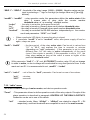
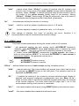
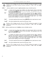
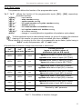
1
®
SIMEX
USER MANUAL for
quadrature counter
family:
type:
SLK-94T
firmware version: 4.02 or higher
Read the user's manual carefully before starting to use the unit.
Producer reserves the right to implement changes without prior notice.
13.01.2010
V.2.01
User manual for quadrature counter SLK-94T
CONTENTS
1. BASIC REQUIREMENTS AND USER SAFETY.........................................................................................3
2. GENERAL CHARACTERISTICS................................................................................................................4
3. TECHNICAL DATA......................................................................................................................................4
4. DEVICE INSTALLATION.............................................................................................................................6
4.1. UNPACKING.......................................................................................................................................6
4.2. ASSEMBLY.........................................................................................................................................6
4.3. CONNECTION METHOD...................................................................................................................9
4.4. MAINTENANCE................................................................................................................................14
5. FRONT PANEL DESCRIPTION................................................................................................................15
6. PRINCIPLE OF OPERATION....................................................................................................................16
6.1. MEASUREMENT MODE..................................................................................................................16
6.2. SELECTING OF DISPLAYED VALUE.............................................................................................18
6.3. CONTROL OF THE RELAY OUTPUTS...........................................................................................20
6.3.1. „Standard” mode (distance measurement)..............................................................................21
6.3.2. „Marker” mode (marking of the distance)................................................................................23
7. DEVICE PROGRAMMING.........................................................................................................................25
7.1. PROGRAMMING MENU...................................................................................................................25
7.2. PARAMETERS EDITION..................................................................................................................26
7.2.1. Numeric parameters (digit change mode)...............................................................................26
7.2.2. Numeric parameters (slide change mode)..............................................................................26
7.2.3. Switch parameters (“LIST” type).............................................................................................26
7.3. MENU DESCRIPTION......................................................................................................................27
7.3.1. “rELAy1” ÷ “rELAy4” menu......................................................................................................27
7.3.2. “mAin” menu............................................................................................................................28
7.3.3. “rESEtS” menu.........................................................................................................................29
7.3.4. “Pr In” menu.............................................................................................................................31
7.3.5. ”PrESCA” menu ......................................................................................................................32
7.3.6. ”rS-485” menu..........................................................................................................................32
7.3.7. Menu ”SECu”...........................................................................................................................33
7.3.8. ”briGHt” parameter...................................................................................................................35
7.3.9. ”Edit” parameter.......................................................................................................................35
7.3.10. ”dEFS” parameter..................................................................................................................35
7.4. MENU STRUCTURE........................................................................................................................36
8. EXAMPLES OF PRESCALER PARAMETERS CALCULATION.............................................................38
9. OBSŁUGA PROTOKOŁU MODBUS........................................................................................................39
9.1. LIST OF REGISTERS.......................................................................................................................39
9.2. TRANSMISSION ERRORS DESCRIPTION.....................................................................................44
9.3. EXAMPLES OF QUERY/ANSWER FRAMES..................................................................................44
10. DEFAULT AND USER'S SETTINGS LIST..............................................................................................47
2
User manual for quadrature counter SLK-94T
Explanation of symbols used in the manual:
!
- This symbol denotes especially important guidelines concerning the installation and
operation of the device. Not complying with the guidelines denoted by this symbol may
cause an accident, damage or equipment destruction.
IF THE DEVICE IS NOT USED ACCORDING TO THE MANUAL THE USER IS
RESPONSIBLE FOR POSSIBLE DAMAGES.
i
- This symbol denotes especially important characteristics of the unit.
Read any information regarding this symbol carefully
1. BASIC REQUIREMENTS AND USER SAFETY
!
- The manufacturer is not responsible for any damages caused by
inappropriate installation, not maintaining the proper technical condition
and using the unit against its destination.
- Installation should be conducted by qualified personnel . During installation all
available safety requirements should be considered. The fitter is responsible for
executing the installation according to this manual, local safety and EMC
regulations.
- The unit must be properly set-up, according to the application. Incorrect
configuration can cause defective operation, which can lead to unit damage or
an accident.
- If in the case of a defect of unit operation there is a risk of a serious threat
to the safety of people or property additional, independent systems and
solutions to prevent such a threat must be used.
- The unit uses dangerous voltage that can cause a lethal accident. The unit
must be switched off and disconnected from the power supply prior to
starting installation of troubleshooting (in the case of malfunction).
- Neighbouring and mating equipment must meet the requirements of appropriate
standards and regulations concerning safety and be equipped with adequate
anti-overvoltage and anti-interference filters.
- Do not attempt to disassemble, repair or modify the unit yourself. The unit
has no user serviceable parts. Units, in which a defect was stated must be
disconnected and submitted for repairs at an authorized service centre.
!
- In order to minimize fire or electric shock hazard, the unit must be protected
against atmospheric precipitation and excessive humidity.
- Do not use the unit in areas threatened with excessive shocks, vibrations, dust,
humidity, corrosive gasses and oils.
3
User manual for quadrature counter SLK-94T
!
- Do not use the unit in explosion hazard areas.
- Do not use the unit in areas with significant temperature variations, exposed to
condensation or icing.
- Do not use the unit in areas exposed to direct sunlight.
- Make sure that the ambient temperature (e.g. inside the control box) does not
exceed the recommended values. In such cases forced cooling of the unit must
be considered (e.g. by using a ventilator).
!
The unit is designed for operation in an industrial environment and must
not be used in a household environment or similar.
2. GENERAL CHARACTERISTICS
The counter type SLK-94T is designed to cooperation with quadrature incremental
encoders. Settable recalculation factors (multiplier, divider and offset) allow displaying of the
result in desired units. It is possible to define four sets of recalculation coefficients mul-divoffset-point (it means profiles), these profiles make recalculation between units easier. Main
counter range is limited from -99999 to 999999. Build-in totalizer is 12 digits long (99999999999 to 999999999999).
The unit can control up to 4 external devices (motors, signalising devices) via build in relay
outputs, every in one of two modes (NO and NC). Activation of particular output can be done
after achieving of preset value (threshold) by the counter. Deactivation of the output can be
done after selected time (0 to 99.9 seconds or minutes) or when counted value goes less than
selected threshold related to particular output. The autoreset function allows zeroing of the
counter by itself when it reaches the threshold, and build in cycles counter counts the number of
autoresets. Manual zeroing of the counter causes storing of present value into internal “resets
memory” and makes possibility of its viewing in future (maximum 5 last resets).
SLK-94T is equipped in 2 programmable inputs which allows external reset of selected
counter (or group of counters) or change of counting direction (regardless of quadrature signal
phase).
All internal registers of the counter (including direct driving of relays) are available via RS-485
interface (with MODBUS RTU protocol). All inputs of the counter are separated .
3. TECHNICAL DATA
Power supply voltage
(depending on version)
85...230...260V AC/DC; 50 ÷ 60 Hz
19...24...50V DC; 16...24...35V AC
External fuse (required)
T - type, max. 2 A
Power consumption
max. 4,5 VA @ 85 ÷ 260V AC/DC
max. 4,5 VA @ 16V ÷ 35V AC
max. 4,5 W @ 19V ÷ 50V DC
4
User manual for quadrature counter SLK-94T
Pulse inputs
A and B inputs
IN1 input
IN2 input
COM
quadrature, counting (terminal no. 18,19)
first programmable input (terminal no. 16)
second programmable input (terminal no. 17)
common terminal (terminal no. 20)
Input levels
low level:
high level:
0V ÷ 1V
10V ÷ 30V (about 12 mA @ 24V)
Input frequency
max. 250 kHz
Outputs
relay:
or OC-type:
sensor power supply:
Measurement range
main counter:
cycles counter:
”standard” mode
„marker” mode
totalizer counter:
4 NO, 1A/250V AC (cos ϕ = 1)
4 30mA / 30VDC / 100mW
24V +5%, -10% / max. 100 mA, stabilized
-99 999 ÷ 999 999, plus decimal point
0 ÷ 999 999
-99 999 ÷ 999 999, plus decimal point
-99 999 999 999 ÷ 999 999 999 999
Communication interface
RS 485, 8N1 and 8N2, Modbus RTU, not separated
Baud rate
1200 bit/s ÷ 115200 bit/s
Display
LED, 6 digit, 13mm height, red
Data memory
non-volatile memory, EEPROM type
Protection level
IP 65 (from front, after using waterproof cover)
IP 40 (from front)
IP 20 (housing and connection clips)
panel
NORYL - GFN2S E1
96 x 48 x 100 mm
90,5 x 43 mm
102 mm
max. 5 mm
0°C to +50°C
-10°C to +70°C
5 to 90% no condensation
up to 2000 meters above sea level
Housing type
Housing material
Housing dimensions
Mounting hole
Assembly depth
Panel thickness
Operating temperature
Storage temperature
Humidity
Altitude
Screws tightening max. torque
Max. connection leads diameter
Safety requirements
0,5 Nm
2,5 mm2
according to: PN-EN 61010-1
installation category: II
pollution degree: 2
voltage in relation to ground: 300V AC
5
User manual for quadrature counter SLK-94T
insulation resistance: >20MΩ
insulation strength between power supply and
input/output terminal: 1min. @ 2300V
insulation strength between relays terminal: 1min. @
1350V
according to: PN-EN 61326-1
EMC
!
This is a class A unit. In housing or a similar area it can cause radio
frequency interference. In such cases the user can be requested to use
appropriate preventive measures.
4. DEVICE INSTALLATION
The unit has been designed and manufactured in a way assuring a high level of user
safety and resistance to interference occurring in a typical industrial environment. In order to
take full advantage of these characteristics installation of the unit must be conducted correctly
and according to the local regulations.
!
- Read the basic safety requirements on page 3 prior to starting the installation.
- Ensure that the power supply network voltage corresponds to the nominal
voltage stated on the unit’s identification label.
- The load must correspond to the requirements listed in the technical data.
- All installation works must be conducted with a disconnected power supply.
- Protecting the power supply clamps against unauthorized persons must be
taken into consideration.
4.1. UNPACKING
After removing the unit from the protective packaging, check for transportation damage.
Any transportation damage must be immediately reported to the carrier. Also, write down the
unit serial number on the housing and report the damage to the manufacturer.
Attached with the unit please find:
- user’s manual,
- warranty,
- assembly brackets - 2 pieces.
4.2. ASSEMBLY
!
- The unit is designed for mounting indoor inside housings (control panel,
switchboard) assuring appropriate protection against electric impulse waves. Metal
housing must be connected to the grounding in a way complying with the
governing regulations.
- Disconnect the power supply prior to starting assembly.
6
User manual for quadrature counter SLK-94T
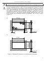
In order to assembly the unit, a 90.5 x 43 mm mounting hole (Figure 4.1) must be
prepared. The thickness of the material of which the panel is made must not exceed
5mm. When preparing the mounting hole take the grooves for catches located on
both sides of the housing into consideration (Figure 4.1). Place the unit in the
mounting hole inserting it from the front side of the panel, and then fix it using the
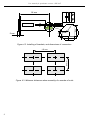
brackets (Figure 4.2). The minimum distances between assembly holes’ axes - due
to the thermal and mechanical conditions of operation - are 115 mm x 67mm
(Figure 4.3).
a)
90,5 mm
13 mm
8 mm
43 mm
!
- Check the correctness of the performed connections prior to switching the unit on.
8 mm
13 mm
1 mm
1 mm
max. 5 mm
b)
92 mm
43 mm
!
max. 5 mm
Figure 4.1. Mounting hole dimensions: a) recommended b) allowable
7
User manual for quadrature counter SLK-94T
8,5 mm
16 mm
92 mm
5 mm
12 mm
10 mm
Figure 4.2. Installing of brackets, and dimensions of connectors.
67 mm
115 mm
Figure 4.3. Minimum distances when assembly of a number of units
8
User manual for quadrature counter SLK-94T
4.3. CONNECTION METHOD
Caution
!
- Installation should be conducted by qualified personnel . During installation all
available safety requirements should be considered. The fitter is responsible for
executing the installation according to this manual, local safety and EMC
regulations.
- The unit is not equipped with an internal fuse or power supply circuit breaker.
Because of this an external time-delay cut-out fuse with minimal possible nominal
current value must be used (recommended bipolar, max. 2A) and a power supply
circuit-breaker located near the unit. In the case of using a monopolar fuse it must
be mounted on the phase cable (L).
- The power supply network cable diameter must be selected in such a way that in
the case of a short circuit of the cable from the side of the unit the cable shall be
protected against destruction with an electrical installation fuse.
- Wiring must meet appropriate standards and local regulations and laws.
- In order to secure against accidental short circuit the connection cables must be
terminated with appropriate insulated cable tips.
- Tighten the clamping screws. The recommended tightening torque is 0.5 Nm.
Loose screws can cause fire or defective operation. Over tightening can lead to
damaging the connections inside the units and breaking the thread.
- In the case of the unit being fitted with separable clamps they should be inserted
into appropriate connectors in the unit, even if they are not used for any
connections.
- Unused clamps (marked as n.c.) must not be used for connecting any
connecting cables (e.g. as bridges), because this can cause damage to the
equipment or electric shock.
- If the unit is equipped with housing, covers and sealing packing, protecting against
water intrusion, pay special attention to their correct tightening or clamping. In the
case of any doubt consider using additional preventive measures (covers, roofing,
seals, etc.). Carelessly executed assembly can increase the risk of electric shock.
- After the installation is completed do not touch the unit’s connections when it is
switched on, because it carries the risk of electrical shock.
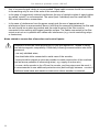
Due to possible significant interference in industrial installations appropriate measures assuring
correct operation of the unit must be applied. To avoid the unit of improper indications keep
recommendations listed below.
–
Avoid common (parallel) leading of signal cables and transmission cables together with
power supply cables and cables controlling induction loads (e.g. contactors). Such cables
should cross at a right angle.
–
Contactor coils and induction loads should be equipped with anti-interference protection
systems, e.g. RC-type.
9
User manual for quadrature counter SLK-94T
–
Use of screened signal cables is recommended. Signal cable screens should be connected
to the earthing only at one of the ends of the screened cable.
–
In the case of magnetically induced interference the use of twisted couples of signal cables
(so-called “spirals”) is recommended. The spiral (best if shielded) must be used with RS485 serial transmission connections.
–
In the case of interference from the power supply side the use of appropriate antiinterference filters is recommended. Bear in mind that the connection between the filter and
the unit should be as short as possible and the metal housing of the filter must be
connected to the earthing with largest possible surface. The cables connected to the filter
output must not run in parallel with cables with interference (e.g. circuits controlling relays
or contactors).
Notes related to connection of encoders and control inputs:
!
Installation should be made accordingly to local law regulations, related to safety
and electromagnetic compatibility. Essentially following recommendation should be
preserved.
- use only shielded wires;
- the shield should be connected to metal case of the encoder,
- wires should be placed as close as possible to metal construction of the machine
and as fare as possible of inferencing wires ( e.g. supply of motors etc.)
- in case, while encoder is far off from the counter, and long wires must be used, it
is recommended to use additional protection wire (bold enough) between counter's
additional metal case and machine construction where encoder is mounted .
10
User manual for quadrature counter SLK-94T
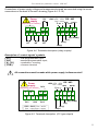
Connections of power supply voltage and measurement signals are executed using the screw
connections on the back of the unit’s housing (Figure 4.4 - 4.10).
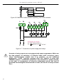
R4
Power
supply
+ Uo -
(depending on version)
1
2
+24V +5%, -10% RS - 485
Imax = 100mA GND
DATA+
DATA-
3 4
5 6 7 8 9
10 11 12 13 14 15
16 17 18 19 20
R1
R2
R3
A(+) COM(-)
B(+)
IN1(+)
IN2(+)
Figure 4.4. Terminals description (relay outputs)
Description of control signals' symbols.
{ IN1 }
{ IN2 }
{ A },{ B }
{ COM }
!
- first programmable input;
- second programmable input;
- quadrature, counting;
- common terminal
All connections must be made while power supply is disconnected !
Power
supply
(depending on version) OC4
+
1
3 4
2
10 11 12 13 14 15
-
+
OC1
+ OC2
+ OC3
OC1 ÷ OC4: Umax = 30V DC,
Imax = 30mA, Pmax = 100mW
+24V +5%, -10% RS - 485
Imax = 100mA GND
DATA+
+ Uo -
DATA-
5 6 7 8 9
16 17 18 19 20
A(+) COM(-)
B(+)
IN1(+)
IN2(+)
Figure 4.5. Terminals description (OC-type outputs)
11
User manual for quadrature counter SLK-94T
max. 2 mm
6-7 mm
Figure 4.6. Method of cable insulation replacing and cable terminals
R4
L
N
1
2
R1
R2
R3
3 4
10 11 12 13 14 15
FUSE
FUSE
L
N
Depending on version:
85...230...260V AC/DC or
19...24...50V DC; 16...24...35V AC
Figure 4.7. Connection of power supply and relays
!
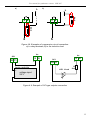
12
Contacts of relay outputs are not equipped with spark suppressors. While use
the relay outputs for switching of inductive loads (coils, contactors, power
relays, electromagnets, motors etc.) it is required
to use additional
suppression circuit (typically capacitor 47nF/ min. 250VAC in series with
100R/5W resistor), connected in parallel to relay terminals or (better) directly
on the load. In consequence of using the suppression circuit, the level of
generated electromagnetic disturbances is lower, and the life of relay contacts
rises.
User manual for quadrature counter SLK-94T
a)
b)
L
3 4
L
!
3 4
!
N
N
Figure 4.8. Examples of suppression circuit connection:
a) to relay terminals; b) to the inductive load
Uo
OC1
5 6
10 11
-
Uo
+
+
Logic controller
+
voltage input
24 V
-
5 6
OC1
-
+
10 11
-
+
LED 10 mA
-
R
2k2
Figure 4.9. Example of OC-type outputs connection
13
User manual for quadrature counter SLK-94T
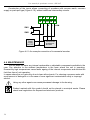
Construction of the inputs allows connecting of encoders with common earth, common
supply or push-pull type (Figure 4.10), without additional intermediary circuits.
5 6 7 8 9
16 17 18 19 20
B
A
COM
SW1
SW2
Power
supply
24V DC
+
Incremental
quadrature
encoder
Figure 4.10. An example connection of incremental encoder.
4.4. MAINTENANCE
The unit does not have any internal replaceable or adjustable components available to the
user. Pay attention to the ambient temperature in the room where the unit is operating.
Excessively high temperatures cause faster ageing of the internal components and shorten the
fault-free time of unit operation.
In cases where the unit gets dirty do not clean with solvents. For cleaning use warm water with
small amount of detergent or in the case of more significant contamination ethyl or isopropyl
alcohol.
!
Using any other agents can cause permanent damage to the housing.
Product marked with this symbol should not be placed in municipal waste. Please
check local regulations for disposal and electronic products.
14
User manual for quadrature counter SLK-94T
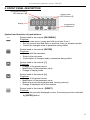
5. FRONT PANEL DESCRIPTION
Thresholds exceeding
LED indicators (R)
display mode
LED indicator (F)
R1
R2
R3
R4
F
display
ESC
MENU
ENTER
RESET
programming
pushbuttons
Symbols and functions of push-buttons:
ESC
MENU
ENTER
Symbol used in the manual: [ESC/MENU]
Functions:
• Enter to main menu ( press and hold by at least 2 sec.)
• Exit the current level and Enter to previous menu (or measure mode)
• Cancel the changes made in parameter being edited
Symbol used in the manual: [ENTER]
Functions:
• Start to edit the parameter
• Enter to the sub-menu,
• Confirmation of changes made in parameter being edited
Symbol used in the manual: [^]
Functions:
• Change of the present menu,
• Modification of the parameter value,
• Change of display mode
Symbol used in the manual: [v]
Functions:
• Change of the present menu,
• Modification of the parameter value,
• Monitoring of current thresholds and “zeroing memory”,
• Change of displayed half of the totalizer
RESET
Symbol used in the manual: [RESET]
Functions:
• zeroing the currently displayed counter, the zeroing must be confirmed
by [ENTER] button.
15
User manual for quadrature counter SLK-94T
6. PRINCIPLE OF OPERATION
After turning the power supply on, device ID and software version are showed on the
display, next the data stored while power supply off is restored and device goes to the
selected operation mode. The counter restores also displaying mode, it means shows counter
which was displayed before power down.
6.1. MEASUREMENT MODE
In this state display shows current value of the main counter, cycles counter or
totalizer.
Switching between counters can be done using [^] button.
The type of currently presented counter is signalised by LED marked “F” (detailed informations
in chapter CHANGE OF DISPLAYED VALUE).
A input
B input
Content of
main counter
internal registers
Displayed value of
main counter
( muL=”1”, div=”1”)
0
0
1
2
3
1
4
5
6
7
2
8
9
10
11
3
10
9
8
7
6
2
5
4
3
2
1
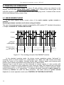
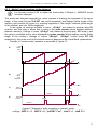
Figure 6.1. The counting principle of the SLK-94T counters
In the standard counting mode, the device counts quadrature pulses “delivered” to
counting inputs A and B (Figure 6.1), recalculates it by “muL” and “div” factors and finally
shows the result on the display. Settable divider (div), multiplier (muL) and decimal point
position (point) allow recalculation the pulses directly to desired units.
Impulses from A and B inputs are first delivered to internal register of main counter with
resolution of 4 pulses on every quadrature cycle (pulse per edge), but displayed with resolution
of quadrature cycles. To achieve better resolution (to half or quarter of cycle) parameter “muL”
should increased to 2 or 4 respectively. In addition all pulses counted by main counter are
counted by totalizer too (with the same precision). The state (value) of cycles counter
depends on current operation mode (see: CONTROL OF THE RELAY OUTPUTS).
16
User manual for quadrature counter SLK-94T
If the result is out of permissible counter range (from “-99999” to “999999” for current value
counter), special warning is displayed in place of the result. The warning type depends on the
result and can be:
– “-Hi-” - if the result is higher than “999999”,
– “-Lo-” -if the result is lower than“-99999”,
When a given warning is displayed the counting of corresponding direction is inhibited, and the
relays are opened.
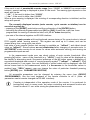
The currently displayed counter (main counter, cycle counter or totalizer) can be
zeroed at any time by:
– pressing of the [RESET] push-button and the confirmation of the [ENTER] button,
– activating the external programmable input {IN1} or {IN2} (if particular input has been
programmed for zeroing of selected counter, see „Pr In” menu description),
– pre-sets of the internal registers via RS-485 interface
Zeroing of main counter with local keyboard causes storing of it's current value in internal
FIFO register called “zeroing memory”. This register can store up to 5 values, and can be
viewed at any time, using quick view mode.
Last state of main counter (before last zeroing) is available as ”mEmo1”, and oldest stored
value as ”mEmo5”. Stored values are not recalculated after changing of prescaler sets. In
AUTORESET mode counter do not stores it's values while automatic zeroing, and zeroing via
programmable inputs as well.
In the measurement mode user can check values of main counter thresholds. After
pressing [v] button, name of the threshold (e.g. ”rELPr1”) and it's value will be displayed on
the display in alternating mode. Successive pressings of the [v] button cause in displaying of
successive thresholds and content of “zeroing memory register” (”mEmo1” ÷ ”mEmo5”). If [v]
will be pressed in 5 sec again, the next threshold or stored resets will be displayed, else the
device comes back to the measurement mode. If a free access to the thresholds values is
enabled (see: ”SECu” menu), user can change the value of particular threshold pressing
button [ENTER] (see: PARAMETERS EDITION).
All accessible parameters can be changed by entering the menu (see: DEVICE
PROGRAMMING). Use the local keyboard or the remote controller to do it. (Note: all
parameters can be remote changed via RS-485 interface).
i
Counting is independent of the operation mode of the counter. It is continued (in
background) even in menu mode, but relays controlling and autoreset function are
frozen for about 0.1 sec. while storing the parameters in menu mode.
17
User manual for quadrature counter SLK-94T
6.2. SELECTING OF DISPLAYED VALUE
The SLK-94T counter allows counting in three separate internal registers (counters).
These registers are called: main counter, cycles counter, and totalizer. Selection of currently
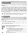
displayed counter (mode of displaying) can be done using [^] button, accordingly to the Figure
6.2.
main counter
cycles counter
totalizer
Figure 6.2. Selection of displaying mode
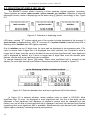
LED lamp, marked “F” informs which one of the counter is being displayed at the moment. If
main counter is displayed then LED “F” is turned off. If cycles counter is showed then LED is
flashing, and if totalizer then LED lights constantly.
Due to totalizer can be 12 digits long, its value can be displayed in two separate parts. If it's
value is shorter than 6 digits then it is displayed like other counters, but if totalizer's value is
longer then 6 digits, then the value is divided into less and more significant half. Less significant
half is displayed by default, but if result is longer than 6 digits then most left decimal point
flashes, informs that more significant part is available.
To change displayed half, press [v] button. When more significant half is showed on the
display, it's most right decimal point flashes. Described situation is showed in Figure 6.3:
go to displaying of other counters content
Figure 6.3. Selection between less and more significant half of the totalizer
In Figure 6.3 is showed situation, where totalizer value is equal to 302128.8. Most
significant digit (3) must be displayed in more significant half, the rest of the digits can be
displayed in less significant half. Because of totaliser's content must be displayed into two
halves, zero on left side of less significant half is displayed, and most left decimal point flashes
signalising that more significant half is available. Simultaneously right decimal point (between
eights) lights constantly, indicating decimal point position.
18
User manual for quadrature counter SLK-94T
To avoid situations when decimal point covers signalisation of more significant half, the range of
decimal point position is limited to four digits (0.0000).
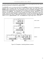
The SLK-94T counter, can store which half of the totalizer is selected to be displayed. If more
significant half is selected, and user goes to other counters values, then after switching to
totalizer again (using [^] button), more significant half will be displayed immediately. If less
significant half is selected then counter goes to this half after next entering to the totalizer. After
zeroing of the totalizer, less significant half is automatically selected, regardless of user
selection, and more significant half will not be available until totalizer content will be longer than
6 digits. Figure 6.4 shows examples of switching between counters with selected less and more
significant half of the totalizer. Additionally LED indicator is showed in the figure. Main counter
value is „123.3”; cycles counter is „281”; and totalizer has 7 digits length value „312123.3”.
main counter
cycles counter
depending
on selected half
totalizer
Figure 6.4. Examples of switching between counters
19
User manual for quadrature counter SLK-94T
6.3. CONTROL OF THE RELAY OUTPUTS
The control of the object is realised due to main counter value, and/or cycles counter
value, via relay outputs. Front panel LEDs named „R1” ÷ „R4” indicate the state of particular
relay output.
Modes of the control can be changed depend on the values of parameters “SEtP”, “timE” and
“modE”, and additional parameter „Src” for relays R3 and R4 . Relays R1 and R2 has its
factory predefined control sources dependent on selected function of main counter (see
parameter ”Funct” in ”mAin” menu).
Figure 6.5 presents the principle of relay outputs operation for example values of
parameters.
Parameter “SEtP” defines threshold of relay (trace: a). While normal operation of counter,
relay output can change its state to active only if counter value reaches (or exceeds)the
threshold (for „up” counting points A, C, E, G ). The active state of the relay (close or open) is
defined by parameter “modE”. Relays R3 and R4 can be controlled due to result of main
counter or cycle counter. The selection of the source is being done using „Src” parameter in
their menus.
tA
displayed value
tC
main
counter
value
tG
tE
“SEtP” parameter
(threshold value)
a)
D
A
tZ
b)
c)
d)
e)
relay state
(modE = on
timE = 0)
relay state
(modE = oFF
timE = 0)
relay state
(modE = on
timE > 0)
relay state
(modE = oFF
timE > 0)
B
F
G
time
closed
opened
time
closed
time
opened
closed
opened
“timE”
“timE”
tX
“timE”
“timE”
tX
“timE”
closed
time
- time points points where result exceeds thresholds value,
- time while counter keeps result at least equal to threshold value
- time between subsequent exceeds of threshold value (shorter than value of “timE”parameter )
- delay of relay reaction
Figure 6.5 Principle of relay outputs operation
20
time
opened
“timE”
Description:
A, B, C, D, E, F, G
tA , tC , tE , tG
tX
tZ
E
C
User manual for quadrature counter SLK-94T
i
The reaction of the counter on reaching of “threshold values” is not momentary,
maximum delay in relay control (switch on or off of the relay) while output is being
driven from main counter is less than 12 ms for outputs OC type, and 20ms for
electromechanical relays.
Parameter “timE” defines how long relay stay active after its activation by counter value (after
moment when counter has reached particular threshold).
• If parameter “timE” is set to “0”, then relay stays in active state (periods: tA ,tC ,tE ,tG) as
long as counter value is equal or higher than threshold value. (traces: b, c). In case when
periods tA ,tC ,tE ,tG are shorter than delay of relay reaction (tZ time), the relay can not change
it's state to active.
• If parameter “timE” is set to value different from “0”, then relay stay active during defined
time regardless of counter value (traces: d, e). In case when period (tX) between successive
exceedings of threshold value (e.g. between points B and C) is shorter than period defined
by parameter “timE”, activation period of relay is prolonged by “timE” (every time when
counter value goes up and reaches threshold).
i
If parameter “timE” = “0” and AUTORESET function is active, particular relay will not
change it's state to active.
If alarm situation occurs, (e.g. counter value is greater than allowable displaying
range) all relays are opened.
Parameter “modE” can be set to value “modbuS”. In such case it is possible to drive relays
via RS-485 interface. In this case relays are independent on counter value, „timE” and „SEtP”
settings, and change of it's state can be done exclusively via RS-485 interface, as presets of
holding registers (see: LIST OF REGISTERS) . While parameter “modE” is set to value ”on”
or ”oFF”, presets of these registers do not causes any reaction, and reading of these registers
show actual state of particular relays.
i
If “modbuS” mode is active, than after power down and up relays are inactive.
All parameters corresponding to relay outputs are described in details in chapter
”rELAy1” ÷ ”rELAy4” menu
The counter SLK-94T (it's relay outputs) can operate in one of two modes („standard”
mode or „marker” mode) selected via option ”Funct” of ”mAin”menu. Principle of operation
of both „standard” and „marker” modes are described below.
6.3.1. „Standard” mode (distance measurement)
In this mode (Figure 6.6) settings available in menu “rELAy1” ÷ “rELAy4” are related directly
to relays R1 ÷ R4. Relays' R1 and R2 thresholds are compared to main counter value, and
relays' R3 and R4 thresholds are compared to source selected by Src 3 and Src 4 parameters
respectively. Relays are driven due to the comparison's result. The value of the main counter
is calculated accordingly to formula:
D v =M c ×
where:
"muL"
1
× Offset
"div"
4
Dv – displayed value
Mc - content of main counter internal registers
21
User manual for quadrature counter SLK-94T
Cycles counter displays current number of made autozeroings, and totalizer displays the sum
of all pulses recalculated to desired units accordingly to formula:
B= L t ×
where:
a)
"muL"
1
×
"div"
4
B – displayed value
Lt - content of totalizer internal registers
main
counter
value
10
8
time
b)
cycle
counter
value
c)
state of
relay R1
time
closed
opened
d)
time
state of
relay R2
closed
opened
time
Figure 6.6 Example of relay controlling in „standard” mode;
settings: „SEtP 1”=10, „SEtP 2”=8, „ArESEt”=”on”, „timE 1”>0, „timE 2”>0
In „Std” mode It is possible to set AUTORESET function for “SEtP 1” threshold. This
function enables automatic zeroing of the counter after, its value reaches relay R1 threshold
(Figure 6.6, traces: a, c ). If AUTORESET function is active, then relays R2 to R4 can be
activated if their thresholds are not greater than relay R1 threshold (Figure 6.6, traces: a, d ) or
if R3 and R4 are being controlled by cycle counter.
22
User manual for quadrature counter SLK-94T
6.3.2. „Marker” mode (marking of the distance)
i
For firmware version 4.02 or higher the functionality of Relays in MARKER mode
has been changed.
This mode was designed especially to realize process of marking the segments of the same
length. In this mode counter SLK-94T can counts segments, and displays global length of the
medium, and controls the cutter (e.g. marking segments of 10m length, measure global length
of the medium, and cuts 1000m segments).
In this mode, all settings available in menu “rELAy1” are related to physical relay R1
(marker), and this relay is driven due to value of the main counter (which displays distance
between markers). Settings in menu “rELAy2” are related to physical relay R2 (cutter), and
this relay is controlled due to value displayed by cycles counter (which displays current global
length of the medium). Settings in menus “rELAy3”, “rELAy4” control relays R3, R4
respectively, due to the result of the selected source (depend on Src 3 and Src 4 parameters).
Principle of “marker mode” operation is presented in Figure 6.7.
a)
main
counter
value
10
time
b)
cycle
counter
value
(distance)
time
c)
state of
relay R2
closed
opened
d)
time
state of
relay R1
closed
opened
time
Figure 6.7 Example of relay controlling in „marker” mode;
settings: „SEtP 1”=10, „SEtP 2”=22, „ArESEt”=”on”, „timE 1”>0, „timE 2”>0
23
User manual for quadrature counter SLK-94T
Distance between markers (e.g 10m) can be set via parameter “SEtP 1”, it mean relay R1
should drive marker (mechanical or printer; Figure 6.7, traces: a, d). The global length of the cut
segments (e.g. 22m, it needn't to be integer multiplicity of marked segments “SEtP 1”) user can
set changing parameter “SEtP 2”, it mean relay R2 should drive the cutter.
In marker mode, main counter displays current distance between markers, and setting
“SEtP 1” is compared to this value (Figure 6.7, traces: a, c). It's content is cleared when it
reaches value equal „SEtP 1”, independently of parameter „ArESEt”. Cycles counter
displays global distance since last cut (current length of the medium).
In marker mode main counter displays value calculated using the formula:
M DV =M c ×
where:
"muL"
1
× Offset
"div"
4
MDV - displayed value (current distance since last marker)
MC - content of main counter's internal registers
Cycles counter displays global length of the medium as the result of the formula:
G L= A M × "SEtP 1" M DV
where:
GL - displayed value (global length)
AM - number of markers (autozeroings of main counter)
MDV - current value of main counter (current distance since last marker)
If setting „ArESEt” =”on”, and cycles counter reach threshold defined by „SEtP 2”, then
only content of cycles counter will be zeroed (Figure 6.7, traces: a, b), content of the main
counter will be preserved. In case when it is necessary to clear the main counter too, then it is
recommended to use programmable input with proper configuration.
If setting „ArESEt” =”off ” and cycles counter reach threshold defined by „SEtP 2”, then
cycles counter counts as before and relay “rELAy2” is controlled due to settings of
parameters „modE 2” and „timE 2”.
It is strongly recommended to set threshold of R1 smaller than threshold of R2. In other case
the autoreset of cycle counter may not behave in expected way (the cycle counter - distance will
not be cleared, will be counting until main counter reaches R1 threshold, and displaying value
equals to main counter value).
In marker mode totalizer displays the sum of all pulses recalculated to desired units
accordingly to formula:
B= L t ×
where:
24
"muL"
1
×
"div"
4
B – displayed value
Lt - content of totalizer internal registers
User manual for quadrature counter SLK-94T
7. DEVICE PROGRAMMING
The device menu allow user to set all parameters connected to operation of measurement
input, control modes, critical situations behaviour, communication via RS-485 and access
settings. The meaning of the particular parameters is described in paragraph MENU
DESCRIPTION.
Some of the parameters can be accessed without menu entering (quick view mode). After
pressing [v] button, name of the threshold (e.g. ”rELPr1”) and it's value will be displayed on
the display in alternating mode. Successive pressing of [v] button cause in displaying of
registers ”mEmo1” ÷ ”mEmo5” content. If [v] will be pressed in 5 sec again, the next
threshold or stored resets will be displayed, else the device comes back to the measurement
mode. If a thresholds values free access is enabled (see: ”SECu” menu), user can change
the value of particular threshold pressing button [ENTER] (see: PARAMETERS EDITION).
If free access to profile changes is set, (see Menu ”SECu”), then user can change profile
without knowing of main password.
i
If particular parameter has been changed and confirmed in quick view mode, its new
value is displayed in alternating mode with parameter name by few seconds. User can
check confirmed changes or switch viewed parameter pressing [v] button.
7.1. PROGRAMMING MENU
To enter main menu (being in the measurement mode) operator must to press and hold at
least 2 sec. [ESC/MENU] button. If the user password is defined (see parameter “SEtCod“,
menu ”SECU”), operator have to enter correct one before proceeding to menu options.
Entering of the passwords is similar to the edition of numeric parameters (see: PARAMETERS
EDITION), however presently editing digit is showed only on the display, other digits are
replaced by “-” sign.
After entering of last digit of the password first menu position will be displayed (if the
password is correct) or warning ”Error” in other case.
!
Pay attention when device parameters are being changed. If it is possible, turn off
controlled installation (machine).
Functions of the buttons while sub-menu and parameters choice:
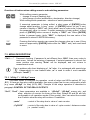
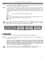
Selection of sub-menu or parameter for editing. Name of selected item (submenu or parameter) is displayed.
ENTER
ESC
MENU
Operation of [ENTER] button depend on present menu position:
• if the name of some sub-menu is displayed - enter this sub-menu; name
of the first parameter (or next level sub-menu) is displayed,
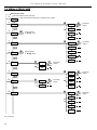
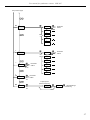
• if the name of some parameter is displayed - enter the edition of this
parameter; present value of the parameter is displayed,
[ESC/MENU] button allow user to exit present menu level and goes to upper
level menu (or measurement mode).
25
User manual for quadrature counter SLK-94T
i
After about 1 min. since last use of the buttons, device exits the menu mode and
returns to the measurement mode (only if no parameters are in editing mode).
7.2. PARAMETERS EDITION
To start edition of any parameter user should select name of desired one using [^] [v]
buttons and then press [ENTER].
7.2.1. Numeric parameters (digit change mode)
Numerical parameters are displayed as decimal numbers. The mode of its new value entering
depends on chosen edit method ( see parameter „Edit”).
In mode “by digit” („Edit”=”dig”) pressing one of the keys [^] or [v] causes change of
current position (flashing digit) or the sign (+/-). Short pressing of the [ENTER] button causes
change of the position (digit).
Press [ENTER] at least 2 seconds to accept the changes, after that question ”SEt?” is
displayed, and user must to confirm (or cancel) the changes. To conform changes (and story it
in EEPROM) press [ENTER] button shortly after ”SEt?” is displayed. To cancel the changes
press [ESC] button shortly after ”SEt?” is displayed. After that device returns to the menu.
7.2.2. Numeric parameters (slide change mode)
In “slide change” mode („Edit”=”Slid”), buttons [^] and [v] has different functions.
To increase edited value press (or press and hold) [^] button only, the increasing became
quickest as long as button [^] is pressed. To slow down the increasing, button [v] can be used.
If [v] is pressed shortly (and button [^] is still pressed), increasing slow down for a moment
only, if [v] is pressed and held while button [^] is still pressed the increasing slow down and will
be kept on lower speed.
To decrease edited value press (or press and hold ) [v] button only. The decreasing
became quickest as long as button [v] is pressed. To slow down the decreasing, button [^] can
be used. If [^] is pressed shortly (and button [v] is still pressed), decreasing slow down for a
moment only, if [^] is pressed and held while button [v] is still pressed the decreasing slow
down and will be kept on lower speed.
Press [ENTER] at least 2 seconds to accept the changes, after that question ”SEt?” is
displayed, and user must to confirm (or cancel) the changes. To conform changes (and story it
in EEPROM) press [ENTER] button shortly after ”SEt?” is displayed. To cancel the changes
press [ESC] button shortly after ”SEt?” is displayed. After that device returns to the menu.
7.2.3. Switch parameters (“LIST” type)
Switch parameters can be described as a sets of values (a lists) out of which only one of
the options available on the list can be selected for the given parameter. Options of switching
parameter are selected using [^], [v] keys.
Short pressing of [ENTER] causes in displaying of the acknowledge question (”SEt?”). If
key [ENTER] is pressed again, the changes are accepted, stored in EEPROM end the edition
process finished. Pressing the key [ESC] after ”SEt?” causes in cancelling of made changes
and returning to menu.
26
User manual for quadrature counter SLK-94T
Functions of buttons when editing numeric and switching parameters:
While editing numeric parameter:
• change of current (flashing) digit
• slide change of value (acceleration, deceleration, direction change)
While editing switch parameter - selection of switch parameter.
If numerical parameter is being edited, a short press of [ENTER] button
change edited position. A long press of [ENTER] button (at lest 2 sec.)
causes of display a ”SEt?” ask, which allow user to make sure if change of
the parameter value is correct. If switch parameter is being edited, a short
press of [ENTER] button causes of display a ”SEt?” ask. When [ENTER]
button is pressed again (while ”SEt?” is displayed) the new value of the
parameter is stored in EEPROM memory.
ENTER
Pressing this button operator can cancel the changes done up to now (if they
were not approved by [ENTER] button after the ”SEt?” ask) and come back
to menu
ESC
MENU
7.3. MENU DESCRIPTION
“Cd 0 - - -”
i
Password checking. If password is set different from „0000”, than every enter to
main menu follows the entering of password. If entered password is correct first
menu position else warning ”Error” will be displayed, and unit returns to
measurement mode.
Due to problem with direct displaying of “m” letter, it is exchanged with special sign
“
“. Independently in user manual letter „m” is used to make it more readable
(example: “modE”).
7.3.1. “rELAy1” ÷ “rELAy4” menu
This menu allows to configure the operation mode of relays and LEDs marked „R” (e.g.
„R1”). If there are few relay outputs available, then every output has its own configuration menu
(e.g. menu „rELAy2” for relay (LED) „R2”). Principle of the relays operation is described in
paragraph CONTROL OF THE RELAY OUTPUTS.
“Src3”, “Src4” - these parameters are available in “rELAy3”, “rELAy4” menus only, and
allow selection of counter for driving of the relay. Relays R3 and R4 are fully
configurable in all operation modes of the counter. User can select the counter
due to which value the relay will be driven. Possibilities:
„main”
- control of the relay due to value of main counter
„CyCLES”
- control of the relay due to value of cycle counter / distance counter
( in „marker” mode)
27
User manual for quadrature counter SLK-94T
“SEtP 1”÷ “SEtP 4” - threshold of the relay (range -99999 ÷ 999999). Negative values can be
input by selecting a “-” sign on first digit (to change value use [^] and [v]
buttons).
“modE1”÷ “modE4”
“noAct”
“on”
“oFF”
“modbuS”
i
•
•
- relay operation mode, this parameters define the active state of the
relay, it means state of relay while the counter reaches
threshold value, at “up counting”, available modes:
- the relay is not active (permanent turned off)
- the relay is turned on (closed) when result reaches threshold value
- the relay is turned off (opened) when result reaches threshold value
- the relay is controlled via RS-485 interface, independently on the counter
result and parameters “SEtP” and “timE”.
When a particular LED lights, its mean the relay is closed,
If parameter “modE” is set to “modbuS” value, after power supply off and on
again, relays are open.
“timE1”÷ “timE4”
i
- the time period of the relay active state. Can be set to values from
”0.1” to ”99.9”, and express the time in seconds or minutes
(depending on ”unit” parameter). If this parameter is set to value
different from „0.0” the relay is active independently of the result
(even if the counter is zeroed). If this parameter is set to „0.0” the
relay stays active as long as the result is same or higher of the
particular threshold value.
While parameter “timE 1” = “0” and AUTORESET is active, relay R1 will not change
its state to active, or due to delays will be activated for very short period of time. If user
wants not use R1 it is recommended to set „modE 1” =”noAct”.
“unit 1”÷ “unit 4”
“min”
“SEC”
- unit of time for “timE” parameter. Can be set on one of two values:
- minutes,
- seconds.
7.3.2. “mAin” menu
This menu contains settings of main counter, and device operation mode.
”Funct” - This parameter allows to define operation mode of the relay outputs. Principle of the
relays operation is described in paragraph CONTROL OF THE RELAY OUTPUTS.
Parameter can be set to one of the values:
”std”
28
- standard mode. Menu “rELAy1” ÷ “rELAy4” are related to relays R1 ÷ R4
respectively, and their thresholds are compared to result of the main counter.
User manual for quadrature counter SLK-94T
”mAr”
”dir”
- marker mode. Menu “rELAy1” is related to physical relay R1 (marker), and
controls it due to the result of the main counter (current position between two
markers). Menu “rELAy2” is related to physical relay R2 and controls it due to
the content of the cycles counter (global length of the medium). Menus
“rELAy3”, “rELAy4” control relays R3 and R4 respectively, due to the result of
the selected source (depend on Src 3 and Src 4 parameters).
- this parameter defines the direction of counting :
”norm”
- direction equal as phase of quadrature cycle on A -B inputs,
”rEv”
- direction opposite to phase of quadrature cycle on A -B inputs
i
After change of direction, the “jump” of counting can occur, therefore it is
recommended to clear all counters before direction change.
7.3.3. “rESEtS” menu
This menu contains parameters defining the resets modes of all counters.
”ArESEt”
“on”
“oFF”
- this parameter enables the auto zeroing mode (AUTORESET function).In
“standard” mode AUTORESET clears main counter when it reaches the value
equal to „SEtP 1”. The cycle counter has no autoreset function in this mode.
In “marker” mode AUTORESET corresponds to cycles counter, and clears it
when its value reaches „SEtP 2”. In this mode AUTORESET of main counter is
permanently enabled. This parameter can be set to:
- AUTORESET function is active,
- AUTORESET function is inactive.
”rES m” - defines enabled sources of main counter zeroing. Available options:
”mAn”
- manual reset only. This value enables only manual reset, which can be done
by pressing the [RESET] button on the front panel. This operation must to be
approved by [ENTER] button.
”EL”
- it enables the clearing of the counter by external electrical signal, feeded to
selected (and properly configured) programmable input (see Menu „Pr In”).
When an active state is delivered on selected programmable input, the clearing
of the counter happens. The active state must be longer than 1 ms. In this
mode manual clearing of the counter is unavailable.
”ALL”
- this option enables both manual (using [RESET] button) and electronic reset.
”nonE”
- this option disables both manual and electronic reset.
29
User manual for quadrature counter SLK-94T
i
Zeroing of the totalizer can be done via RS-485 interface by presets of some
registers with value 0000h. Remote zeroing is available in ”ALL”, “EL” and “mAn”
modes too.
“rES c”
- defines enabled sources of cycles counter zeroing. Available options:
”mAn”
”EL”
- manual reset only. This value enables only manual reset, which can be done
by pressing the [RESET] button on the front panel. This operation must to be
approved by [ENTER] button.
- it enables the clearing of the counter by external electrical signal, feeded to
selected (and properly configured) programmable input (see Menu „Pr In”).
When an active state is delivered on selected programmable input, the clearing
of the counter happens. The active state must be longer than 1 ms. In this
mode manual clearing of the counter is unavailable.
”ALL”
- this option enables both manual (using [RESET] button) and electronic reset.
”nonE”
- this option disables both manual and electronic reset.
i
Zeroing of the totalizer can be done via RS-485 interface by presets of some
registers with value 0000h. Remote zeroing is available in ”ALL”, “EL” and “mAn”
modes too.
“rES t” - defines enabled sources of totalizer zeroing. Available options:
”mAn”
- manual reset only. This value enables only manual reset, which can be done
by pressing the [RESET] button on the front panel. This operation must to be
approved by [ENTER] button.
”EL”
- it enables the clearing of the counter by external electrical signal, feeded to
selected (and properly configured) programmable input (see Menu „Pr In”).
When an active state is delivered on selected programmable input, the clearing
of the counter happens. The active state must be longer than 1 ms. In this
mode manual clearing of the counter is unavailable.
”ALL”
- this option enables both manual (using [RESET] button) and electronic reset.
”nonE”
- this option disables both manual and electronic reset.
i
30
Zeroing of the totalizer can be done via RS-485 interface by presets of some
registers with value 0000h. Remote zeroing is available in ”ALL”, “EL” and “mAn”
modes too.
User manual for quadrature counter SLK-94T
7.3.4. “Pr In” menu
This parameter defines the function of the programmable inputs.
“In 1”, “In 2” - defines the function of the programmable inputs { IN1 }, { IN2 } respectively.
Available functions:
”diSAbL”
- input inactive,
”rES m”
- main counter zeroing,
”rES c”
- cycles counter zeroing,
”rES mc”
- both main counter and cycles counter zeroing,
”rES t”
- totalizer zeroing,
”rES mt”
- both main counter and totalizer zeroing,
”rES ct”
- both cycles counter and totalizer zeroing,
”rES ALL”
- all counters zeroing,
„dirEct”
- change of counting direction (regardless of quadrature cycle phase)
of this counter (or group) must be enabled (see menu „rESEtS”).
iActualclearing
direction of counting is ex-or sum of programmable inputs states (inputs being in
To allow particular input to clear selected counter (or group of counters) the electrical
“dirEct” mode) and parameter „dir” of „main” menu.
All possibilities of direction change are presented in table below:
Counting direction
„In1”
„In2”
„dir”
(agree or oposite to phase of
parameter parameter parameter
quadrature cycle on A-B inputs)
dirEct
dirEct
norm
agree while states of inputs {IN1}={IN2}
opposite while states of inputs {IN1}≠{IN2}
dirEct
dirEct
rev
opposite while states of inputs {IN1}={IN2}
agree while states of inputs {IN1}≠{IN2}
dirEct
other
norm
agree while state of input {IN1} is active
opposite while state of input {IN1} is inactive
dirEct
other
rev
opposite while state of input {IN1} is active
agree while state of input {IN1} is inactive
other
dirEct
norm
agree while state of input {IN2} is active
opposite while state of input {IN2} is inactive
other
dirEct
rev
opposite while state of input {IN2} is active
agree while state of input {IN2} is inactive
other
other
norm
other
other
rev
Selected by „dir” parameter
Tab.7.1. Possibilities of direction changes
31
User manual for quadrature counter SLK-94T
7.3.5. ”PrESCA” menu
This menu contains parameter which configure the prescalling parameters (recalculations
of counted pulses). This menu allows the user to set individual prescalers, and to scale the
counter in desired units. Available options:
“ProFiL” - selection of the current profile. Profile is the set of the „muL”, „div”, „oFFSEt” and
„Point” factors. It allows quick change of these parameters, what can be useful to
change the units. There are available 4 user profiles, and presently available „muL”,
„div”, „oFFSEt” and „Point”, are related to present profile. To change values of
parameters related with other profile, first selection of desired profile must be done.
“muL”
- multiply coefficient , range -99999 to 999999, ( the multiplier of the current profile
can be changed only)
“div”
- divide coefficient, range 1 do 999999, this parameter defines the internal modulo
counter, (the divider of the current profile can be changed only)
“oFFSEt” - offset coefficient, range: -99999 do 999999 (the offset of the current profile can be
changed only),
“Point”
i
- decimal point position.
•
•
“div” parameter can't be set to “000000”, entered value is controlled by
firmware. “muL” , “div”, „oFFSEt” and „Point” factors for different profiles can
be made after selection of desired profile.
Firmware uses fixed point arithmetic (with rounding down).
7.3.6. ”rS-485” menu
This menu is connected with RS-485 interface, and sets his properties:
”Addr”
- this parameter defines the address of the device, accordingly to Modbus protocol. It
can be set in range from 0 to 199. If the value 0 is set then device, responds to
frames with address 255 (FFh).
”bAud”
- this parameter determines RS-485 interface baud rate. It can be set to one of
8 possible values: ”1.2”, ”2.4”, ”4.8”, ”9.6”, ”19.2”, ”38.4”,”57.6”,”115.2”,
which respond to the baud rates of 1200, 2400, 4800, 9600, 19200, 38400,
57600 and 115200 bit/s respectively.
”mbAccE”
- this parameter sets the access to the configuration registers of the device.
Possible values:
”on”
- configuration registers can be set via RS-485 interface,
”oFF”
- configuration registers can not be set via RS-485 interface.
i
32
The access to registers no 05h ÷ 0Eh cant be denied by ”mbAccE” parameter (see:
LIST OF REGISTERS).
User manual for quadrature counter SLK-94T
”mbtimE” - this parameter defines maximal time (sec) between following frames received by
the device. Parameter “mbtimE” can be set to values from 0 to 99 seconds. The
value 0 means that the time will be not controlled.
”rESP”
- this parameter defines minimal (additional) delay between the Modbus message
and the answer of the device (received and sent via RS-485 interface). This
additional delay allows the device to work with poor RS-converters which do not
works properly on baud rates higher than 19200. This parameter can be set to one of
values:
”Std”
” 10c”
” 20c”
” 50c”
”100c”
”200c”
i
- answer as quick as possible, no additional delay
- answer delayed of 10, 20, 50, 100 of 200 chars respectively, where one
character time depends on selected baud rate
In the most cases parameter ”rESP” should be set to ”Std” (no additional delay).
Unfortunately for some third party RS-converters ”rESP” should be adjusted
experimentally. Table 7.2 contains most frequently used values.
”bAud” parameter
“38.4”
“57.6”
“115.2”
”rESP” parameter
“ 10c”
“ 20c”
“ 50c”
Tab.7.2. Settings of ”rESP” parameter
7.3.7. Menu ”SECu”
This menu contains presets connected with availability of other parameters:
“SEtCod” - user password (4-digits number). If this parameter is set at value “0000”, user
password is turned off.
If the user do not remember his password, the access to the menu is possible
by the “one-use password”. To get this password please contact with
Marketing Division. “Single use password” can be used only one time, after
that it is destroyed. Entering this password causes in clearing of user
password, it means sets the user password to „0000”.
i
The “one-use password” can be used ONE TIME ONLY, it is impossible to use it
again! The “one-use password” can be restored by Service Division only.
33
User manual for quadrature counter SLK-94T
“A rEL1”÷“A rEL4” - this options permits user (”on”) or prohibits (”oFF”) to modify the
thresholds of the relays/LEDs R1 ÷ R4 without knowledge about user
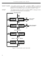
password. The functionality of quick view mode is showed in Figure 7.1.
“A ProF”
- this options permits user (”on”) or prohibits (”oFF”) to change of active
profile without knowledge about user password.
Counting mode
ESC
MENU
ENTER
ProFiL
Profile number
ESC
profile change
(if allowed)
MENU
ESC
MENU
ENTER
rELPr1
Value of
threshold 4
ESC
edition of threshold
value (if allowed)
MENU
rELPr2 ... rELPr4
ESC
MENU
mEmo1
Zeroing
memory 1
mEmo2 ... mEmo3 ... mEmo4
ESC
MENU
mEmo5
Zeroing
memory 5
Figure 7.1 Functionality of quick view mode
34
User manual for quadrature counter SLK-94T
7.3.8. ”briGHt” parameter
This parameter allows user to set bright of the LED display, bright can be set to
conventional values from 1 to 8.
7.3.9. ”Edit” parameter
This parameter allows to change the edition mode of numerical parameters:
”dig”
- the change to “by digit” mode,
”Slid”
- slide change mode.
7.3.10. ”dEFS” parameter
This setting allows to restore the factory settings of the device. To get the access to this
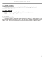
option special password is required: „5465”, next the device displays acknowledge question
„SEt?”. Press [ENTER] to acknowledge the restoring of factory settings or [ESC] to cancel.
35
User manual for quadrature counter SLK-94T
7.4. MENU STRUCTURE
Measurement mode
ESC
ESC
MENU
MENU
Press and hold at least 2 seconds
Cd_ _ _ _
4-digit user password entering (if it is different from „0000”)
ENTER
ESC
MENU
ENTER
rELAy1
ENTER
SEtP 1
ENTER
ESC
MENU
ENTER
ESC
MENU
rELAy2
ESC
Options similar
to „rELAy1” menu
ESC
Parameter
edition
MENU
modE 1
timE 1
MENU
unit 1
ENTER
ESC
MENU
ENTER
Src 3
rELAy3
ENTER
ESC
MENU
ENTER
ESC
MENU
rELAy4
ESC
ESC
Parameter
edition
MENU
SEtP 3
modE 3
Options similar
to „rELAy3” menu
MENU
timE 3
ENTER
ESC
MENU
mAin
unit 3
ENTER
Funct
ENTER
ESC
ESC
Parameter
edition
MENU
MENU
dir
ENTER
ESC
MENU
ENTER
ArESEt
rESEtS
ENTER
ESC
Parameter
edition
MENU
rES m
ENTER
ESC
MENU
In 1
Pr In
ESC
ENTER
ENTER
ESC
ESC
Parameter
edition
MENU
rES c
MENU
MENU
In 2
ENTER
ESC
MENU
rES t
PrESCA
ENTER
ProFiL
ENTER
muL
ESC
MENU
div
oFFSEt
Point
See next page
36
ESC
MENU
Parameter
edition
User manual for quadrature counter SLK-94T
See previous page
ENTER
ESC
MENU
ENTER
Addr
rS-485
ENTER
ESC
Parameter
edition
MENU
bAud
ESC
MENU
mbAccE
mbtimE
rESP
ENTER
ESC
MENU
ENTER
SEtCod
SECu
ENTER
ESC
Parameter
edition
MENU
ESC
MENU
A rEL1
A rEL2
ENTER
ESC
MENU
briGHt
ENTER
ESC
Parameter
edition
A rEL3
MENU
A rEL4
A ProF
ENTER
ESC
MENU
Edit
ESC
Parameter
edition
MENU
4-digit special
password entering
ENTER
ESC
MENU
ENTER
0___
dEFS
MENU
ENTER
SEt?
ESC
Default settings
restoring
ESC
MENU
37
User manual for quadrature counter SLK-94T
8. EXAMPLES OF PRESCALER PARAMETERS CALCULATION
Problem 1: to measure length of the line with assumed precision.
Essential data: - number of pulses per revolution given by sensor
- circumference of measurement circle
- assumed measurement unit and resolution (mm, cm, dm, m).
Example 1
Example 2
Data:
- circumference of measurement circle: 25 cm
- number of pulses: 100 pulses/revolution
- unit cm, resolution 1 cm
Data:
- circumference of measurement circle: 50 cm
- number of pulses: 100 pulses/revolution
- unit dm, resolution 0.1 dm
Settings :
mul = “25”
div = “100”
point = “0.”
Settings:
mul = “50”
div = “100”
point = “0.0”
Problem 2: The chain should be marked every 10m, and cutted in segments of settable
length, with given precision.
To realize this function the counter should be switched to marker mode “Funct” = “mAr”.
The circuit needs at least 2 relays. Relay R2 will be drive the cutter, and R1 the marking divide.
Settings of the markers is realized using menu „rELAy1” („SEtP 1”), and the cutter using
„rELAy2” („SEtP 2” ) - see chapter: The „marker” mode.
User should first collect following data :
• pulses per revolution given by the sensor
• circumference of the measuring wheel
• define smallest unit of the measurement (mm, cm, dm, m).
• define distance between markers, and length of cut segments
Example 3
Example 4
Data:
- circumference of measurement wheel: 25cm
- number of pulses: 100 pulses/revolution
- unit m, resolution 0.1 cm
- marker every 1m, cut segments of 100 m
Data:
- circumference of measurement wheel: 50cm
- number of pulses: 1000 pulses/revolution
- unit dm, resolution 0,01 dm
- marker every 1 dm, cut segments of 10 m =
100 dm
Settings :
mul = “25”
div = “1000”
point = “0.0”
SEtP 1 = 1.0
SEtP 2 = 100.0
38
Settings:
mul = “5”
div = “10”
point = “0.00”
SEtP 1 = 1.00
SEtP 2 = 100.00
User manual for quadrature counter SLK-94T
9. OBSŁUGA PROTOKOŁU MODBUS
Transmission parameters: 1 start bit, 8 data bits, 1 or 2 stop bit (2 bits are send, 1 and 2 bits
are accepted when receive), no parity control
Baud rate:
selectable from: 1200 to 115200 bits/second
Transmission protocol:
MODBUS RTU compatible
The device parameters and display value are available via RS-485 interface, as HOLDING-type
registers (numeric values are given in U2 code) of Modbus RTU protocol. The registers (or
groups of the registers) can be read by 03h function, and wrote by 06h (single registers) or
10h (group of the registers) accordingly to Modbus RTU specification. Maximum group size for
03h and 10h functions can not exceeds 16 registers (for single frame).
i
The device interprets the broadcast messages, but then do not sends the answers.
9.1. LIST OF REGISTERS
Register Write
01h1
No
02h1
No
03h1
No
Range
Register description
Display value - first (higher) word.
depend on
Display value - second word.
value type
Display value - third (lower) word.
High byte - type of the displayed value (reg. 01h, 02h, 03h):
00h or 01h - main counter result
02h or 03h - cycle counter / result or global distance in „marker” mode
04h - more significant half of the totalizer (is displayed)
05h - less significant half of the totalizer (is displayed)
Low byte - the status of the displayed value:
00h - normal ,
see descr. 01h - underflow of cycles counter in „marker” mode
02h - overflow of cycles counter in „marker” mode
04h - cycle counter underflow
08h - cycle counter overflow
10h - totalizer underflow
20h - totalizer overflow
40h - main counter underflow
80h - main counter overflow
04h
Yes
05h2
Yes
see descr. Main counter value - first (higher) word
06h2
Yes
see descr. Main counter value - second word.
07h
2
Yes
see descr. Main counter value - third (lower) word.
08h2
Yes
see descr. Cycle counter value - first (higher) word
09h
Yes
see descr. Cycle counter value - second (lower) word.
2
Yes
see descr. Totalizer value - first (higher) word
0Bh2
Yes
see descr. Totalizer value - second word.
0Ch
Yes
see descr. Totalizer value - third word.
2
0Ah
2
39
User manual for quadrature counter SLK-94T
Register Write
0Dh
Register description
see descr. Totalizer value - fourth (lower) word.
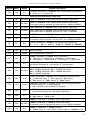
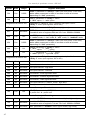
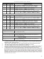
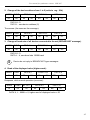
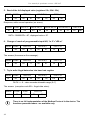
Yes
State of the relays (binary format)
(1 - on, 0 - off): 00000000 0000dcba
see descr. a - relay R1; b - relay R2; c - relay R3; d - relay R4;
If written, only a, b, c,d bits are important (others are ignored) these
bits allows user to control the relays via RS-485 interface
0Fh
No
The state of relays task in binary format
1 – relay was activated (or still is),
0 – relay wasn't activated, and will be as soon as result reaches the
threshold.
see descr.
Format: 0000 0000 0000 dcba
a - relay R1; b - relay R2; c - relay R3; d - relay R4;
This register is very important while relays are activated on defined
period of time. It allows the counter to know if relay was activated or not
10h
Yes
0Eh
11h
12h
13h
40
Range
Yes
2
Yes
Yes
Yes
0÷8
“In 1” parameter in “Pr In” menu (programmable input 1 function):
0 - “diSAbL” mode; 1 - “rES m” mode; 2 - “rES c” mode;
3 - “rES mc” mode; 4 - “rES t” mode; 5 - “rES mt” mode;
6 - “rES ct” mode; 7 - “rES ALL” mode; 8 - “dirEct” mode
0÷8
“In 1” parameter in “Pr In” menu (programmable input 2 function):
0 - “diSAbL” mode; 1 - “rES m” mode; 2 - “rES c” mode;
3 - “rES mc” mode; 4 - “rES t” mode; 5 - “rES mt” mode;
6 - “rES ct” mode; 7 - “rES ALL” mode; 8 - “dirEct” mode
0÷3
“rES m” parameter in “rESEtS” menu (main counter reset source):
0 - “ALL”,
1 - “EL”, reset with { REST } input and RS-485 interface
2 - “mAn”, reset with [RESET] button and RS-485 interface
3 - “nonE” , reset with RS-485 interface only
0÷3
“rES c” parameter in “rESEtS” menu (cycles counter reset source):
0 - “ALL”,
1 - “EL”, reset with { REST } input and RS-485 interface
2 - “mAn”, reset with [RESET] button and RS-485 interface
3 - “nonE” , reset with RS-485 interface only
14h
Yes
0÷3
“rES t” parameter in “rESEtS” menu (totalizer reset source):
0 - “ALL”,
1 - “EL”, reset with { REST } input and RS-485 interface
2 - “mAn”, reset with [RESET] button and RS-485 interface
3 - “nonE” , reset with RS-485 interface only
15h
Yes
0÷1
“ArESEt” parameter in “rESEtS” menu (main counter or cycle counter
autoreset):
0 - “oFF”
1 - “on”
16h
Yes
0÷1
“Funct” parameter in “mAin” menu (relay output activation mode):
0 - “Std” mode;
1 - “mAr” mode
17h
Yes
0÷1
“dir” parameter in “mAin” menu (main counter direction):
0 - “norm” mode
1 - “rev” mode
User manual for quadrature counter SLK-94T
Register Write
18h
Yes
Range
0÷3
Register description
“ProFiL” parameter in “PrESCA” menu (current set of the factors):
0 - profile no1...3 - profile no4
Current profile parameters (read only)
19h
No
see descr. “muL” in “PrESCA” menu (main counter multiplier, high word);
1Ah
No
see descr.
1Bh
No
see descr. “div” parameter in “PrESCA” menu (input divider, high word);
1Ch
No
see descr.
1Dh
No
see descr. “oFFSEt” parameter in “PrESCA” menu (high word)
1Eh
No
see descr.
“oFFSEt” parameter in “PrESCA” menu (low word)
Cumulative value of registers 1Dh and 1Eh: from -99999 to 999999
1Fh
No
0÷5
“Point ” parameter in “PrESCA” menu (decimal point position)
0 - “ 0”; 1 - “ 0.0”; 2 - “ 0.00”; 3 - “0.000”; 4 - “0.0000”; 5 - “0.00000”
20h3
Yes
0 ÷ 199
Device address
21h
No
20D0h
Device identification code (ID)
22h4
Yes
0÷7
“bAud” parameter in “rS-485” menu (baud rate);
0 - 1200 baud; 1 - 2400 baud; 2 - 4800 baud; 3 - 9600 baud;
4 - 19200 baud; 5 - 38400 baud; 6 - 57600 baud; 7 - 115200 baud
23h5
Yes
0÷1
“mbAccE” parameter in “rS-485” menu (permission to write registers
via RS-485 interface); 0 - write denied ; 1 - write allowed
24h
Yes
see descr.
25h
Yes
0÷5
“rESP” parameter in “rS-485” menu (additional response delay);
0 - no additional delay; 1 - ”10c” option; 2 - ”20c” option;
3 - ”50c” option; 4 - ”100c” option; 5 - ”200c” option;
27h
Yes
0÷99
“mbtimE” parameter in “rS-485” menu (maximum delay between
received frames); 0 - no delay checking;
1 ÷ 99 - maximum delay expressed in seconds
2Dh
Yes
1÷8
“briGHt” parameter (display brightness);
1 - the lowest brightness; 8 - the highest brightness
2Fh
Yes
0÷1
“Edit” parameter (numerical parameters edit mode);
0 - „dig” mode; 1 - „SLid” mode
30h6
Yes
see descr. “SEtP 1” parameter in “rELAy 1” menu (high word).
31h6
Yes
see descr.
32h
Yes
0÷3
“muL” in “PrESCA” menu (main counter multiplier, low word);
Cumulative value of registers 19h and 1Ah: from -99999 to 999999
“div” parameter in “PrESCA” menu (input divider, low word);
Cumulative value of registers 1Bh and 1Ch: from 1 to 999999
Parameters of “SECU” menu (binary format (0 - „oFF”, 1 - „on”):
bit 0 - “A rEL1” parameter; bit 1 - “A rEL2” parameter
bit 2 - “A rEL3” parameter; bit 3 - “A rEL4” parameter;
bit 4 - “A ProF” parameter
“SEtP 1” parameter in “rELAy 1” menu (low word).
Cumulative value of registers 30h and 31h: from -99999 to 999999
“modE 1” parameter in “rELAy 1” menu:
0 - “noAct” mode; 1 - “on” mode; 2 - “oFF” mode; 3 - “modbuS” mode
41
User manual for quadrature counter SLK-94T
Register Write
Range
33h
Yes
0÷999
34h
Yes
0÷1
Registers from 38h to 3Ch
Register description
“timE 1” parameter in “rELAy 1” menu (the time period of the relay
active state), expressed in tenth of seconds or tenth of minutes
(depending on “unit” parameter);
“unit 1” parameter in “rELAy 1” menu:
0 - “SEC” option; 1 - “min” option
Parameters in “rELAy 2” menu, registers description like for
“rELAy 1” menu (see registers 30h to 34h)
40h6
Yes
see descr. “SEtP 3” parameter in “rELAy 3” menu (high word).
41h6
Yes
see descr.
42h
Yes
0÷3
43h
Yes
0÷999
44h
Yes
0÷1
“unit 3” parameter in “rELAy 3” menu:
0 - “SEC” option; 1 - “min” option
45h
Yes
0÷1
“Srct 3” parameter in “rELAy 3” menu:
0 - “mAin” option; 1 - “CyCLES” option
Registers from 48h to 4Dh
“SEtP 3” parameter in “rELAy 3” menu (low word).
Cumulative value of registers 40h and 41h: from -99999 to 999999
“modE 3” parameter in “rELAy 3” menu:
0 - “noAct” mode; 1 - “on” mode; 2 - “oFF” mode; 3 - “modbuS” mode
“timE 3” parameter in “rELAy 3” menu (the time period of the relay
active state), expressed in tenth of seconds or tenth of minutes
(depending on “unit” parameter);
Parameters in “rELAy 4” menu, registers description like for
“rELAy 3” menu (see registers 40h to 45h)
50h
No
see descr. The main counter's result - high word
51h
No
see descr. The main counter's result - low word
52h
No
see descr. The cycles counter - high word
53h
No
see descr. The cycles counter - low word
54h
No
see descr. The totalizer - most significant word
55h
No
see descr. The totalizer - medium significant word
56h
No
see descr. The totalizer - least significant word
57h
No
see descr. The cycles counter in “marker” mode - high word
58h
No
see descr. The cycles counter in “marker” mode - low word
Current profile selection
70h
Yes
0÷4
“ProFiL” parameter in “PrESCA” menu (current set of the factors):
0 - profile no1...4 - profile no5
Current profile settings
42
71h
Yes
see descr. “muL” in “PrESCA” menu (main counter multiplier, high word);
72h
Yes
see descr.
73h
Yes
see descr. “div” parameter in “PrESCA” menu (input divider, high word);
“muL” in “PrESCA” menu (main counter multiplier, low word);
Cumulative value of registers 71h and 72h: from -99999 to 999999
User manual for quadrature counter SLK-94T
Register Write
Range
Register description
“div” parameter in “PrESCA” menu (input divider, low word);
Cumulative value of registers 73h and 74h: from 1 to 999999
74h
Yes
see descr.
75h
Yes
see descr. “oFFSEt” parameter in “PrESCA” menu (high word)
76h
Yes
see descr.
77h
Yes
0÷5
79h
Yes
see descr. “muL” in “PrESCA” menu (main counter multiplier, high word);
7Ah
Yes
see descr.
7Bh
Yes
see descr. “div” parameter in “PrESCA” menu (input divider, high word);
7Ch
Yes
see descr.
7Dh
Yes
see descr. “oFFSEt” parameter in “PrESCA” menu (high word)
7Eh
Yes
see descr.
“oFFSEt” parameter in “PrESCA” menu (low word)
Cumulative value of registers 7Dh and 7Eh: from -99999 to 999999
7Fh
Yes
0÷5
“Point ” parameter in “PrESCA” menu (decimal point position)
0 - “ 0”; 1 - “ 0.0”; 2 - “ 0.00”; 3 - “0.000”; 4 - “0.0000”; 5 - “0.00000”
“oFFSEt” parameter in “PrESCA” menu (low word)
Cumulative value of registers 75h and 76h: from -99999 to 999999
“Point ” parameter in “PrESCA” menu (decimal point position)
0 - “ 0”; 1 - “ 0.0”; 2 - “ 0.00”; 3 - “0.000”; 4 - “0.0000”; 5 - “0.00000”
Profile no 1 settings
“muL” in “PrESCA” menu (main counter multiplier, low word);
Cumulative value of registers 79h and 7Ah: from -99999 to 999999
“div” parameter in “PrESCA” menu (input divider, low word);
Cumulative value of registers 7Bh and 7Ch: from 1 to 999999
Profile no 2 settings
Registers from 81h to 87h
Profile no 2 parameters, registers description like for profile no 1
(see registers 78h to 7Eh)
Registers from 89h to 8Fh
Profile no 3 parameters, registers description like for profile no 1
(see registers 78h to 7Eh)
Profile no 3 settings
Profile no 4 settings
Registers from 91h to 97h
1
2
3
4
5
6
Profile no 4 parameters, registers description like for profile no 1
(see registers 78h to 7Eh)
- if overflow or underflow occurs (“-Hi-” or “-Lo-”), read of registers 01h, 02h and 03h (single registers) it returns
recalculated number of pulses ( while the overload of display quantity is very big this value can be erroneous).
Register 03h returns according error code.
- Preset of 0000h to these registers ( 04h÷ 0Dh ) causes by zeroing of main counter and precounter content
- after writing to register no 20h the device responds with an “old” address in the message.
- after writing to register no 22h the device responds with the new baud rate.
- the value of the “mbAc” parameter is also connected to write to this register, so it is possible to block a writes, but
impossible to unblock writes via RS-485 interface, The unblocking of the writes is possible from menu level only.
- numbers written to holding registers of relays thresholds are interrelated with each other auto-correction.
For example. Preset to reg. 31h (threshold lower word) of value, which together with content of register 30h
(threshold higher word) gets value from behind of allowable range, will fails. Over more preset to reg 30h of value
which together with content of register 31h gets value from behind of allowable range, will modify the content of
register 31h, in that way to it's value together with register 30h be located in allowable range. If appropriate
modification is impossible, write fails. It is recommended to write threshold values in presented manner: first preset
of threshold higher word, and next threshold lower word. Similarly storing thresholds registers of another relays is
realised with each other correction.
43
User manual for quadrature counter SLK-94T
9.2. TRANSMISSION ERRORS DESCRIPTION
If an error occurs while write or read of single register, then the device sends an error
code according to Modbus RTU specifications.
Error codes:
01h - illegal function (only functions 03h, 06h and 10h are available),
02h - illegal register address
03h - illegal data value
08h - no write permission ( see: “mbAccE” parameter)
9.3. EXAMPLES OF QUERY/ANSWER FRAMES
Examples apply for device with address 1. All values are represent hexadecimal.
Field description:
ADDR
Device address on Modbus network
FUNC
Function code
REG H,L
Starting address (address of first register to read/write, Hi and Lo byte)
COUNT H,L
No. of registers to read/write (Hi and Lo byte)
BYTE C
Data byte count in answer frame
DATA H,L
Data byte (Hi and Lo byte)
CRC L,H
CRC error check (Hi and Lo byte)
1. Read of device ID code
ADDR
FUNC
REG H,L
01
03
00
ADDR
FUNC
BYTE C
01
03
02
COUNT H,L
21
00
CRC L,H
01
D4
00
The answer:
DATA H,L
20
DATA - identification code (20D0h)
44
D0
CRC L,H
A0
18
User manual for quadrature counter SLK-94T
2. Change of the device address from 1 to 2 (write to reg. 20h)
ADDR
FUNC
01
06
REG H,L
00
DATA H,L
20
00
02
CRC L,H
09
C1
DATA H - 0
DATA L - new device address (2)
The answer (the same as the message):
ADDR
FUNC
01
06
REG H,L
00
DATA H,L
20
00
02
CRC L,H
09
C1
3. Change of baud rate of all devices connected to the net (BROADCAST message).
ADDR
FUNC
00
06
REG H,L
00
COUNT H,L
22
00
04
CRC L,H
29
D2
DATA H - 0
DATA L - 4, new baud rate 19200 baud
i
Device do not reply to BROADCAST-type messages.
4. Read of the displayed value (higher word):
ADDR
FUNC
01
03
REG H,L
00
COUNT H,L
01
00
01
CRC L,H
D5
CA
Response, while normal operation (no errors):
ADDR
FUNC
BYTE C
01
03
02
DATA H,L
00
00
CRC L,H
B8
4C
DATA H, L - 0000h = 0, higher word of displayed value = 00
45
User manual for quadrature counter SLK-94T
5. Read of the full displayed value (registers 01h, 02h i 03h)
ADDR
FUNC
01
03
REG H,L
00
COUNT H,L
01
00
03
CRC L,H
54
0B
Response, while normal operation (no errors):
ADDR
FUNC
BYTE C
01
03
06
DATA H1,L1
00
00
DATA H2,L2
00
00
DATA H3,L3
00
57
CRC L,H
60
8B
DATA - 00000057h = 87, displayed value = 87
6. Change of mode of programmable input IN2, “In 2”=”rES m”
ADDR
FUNC
01
06
REG H,L
00
DATA H,L
11
00
01
CRC L,H
18
0F
The answer (the same as the message):
ADDR
FUNC
01
06
REG H,L
00
DATA H,L
11
00
01
CRC L,H
18
0F
7. Try to write illegal data value into baud rate register
ADDR
FUNC
01
06
REG H,L
00
DATA H,L
22
00
09
CRC L,H
E9
C6
DATA L = 9 - value exceeds allowable range (0÷7)
The answer (exception code 03h - illegal data value):
ADDR
FUNC
ERR
01
86
03
i
46
CRC L,H
02
61
There is no full implementation of the Modbus Protocol in the device. The
functions presented above are available only.
User manual for quadrature counter SLK-94T
10. DEFAULT AND USER'S SETTINGS LIST
Parameter
Description
Default value
User's value
Desc.
page
Parameters of relay R1 operation (“rELAy1” menu)
SEtP 1
Relay threshold
50
28
modE 1
timE 1
Operation mode of relay
on
28
The time period of the relay active state
1.0
28
unit 1
Unit of “timE” parameter
SEC
28
SEtP 2
Relay threshold
100
28
modE 2
Operation mode of relay
on
28
timE 2
The time period of the relay active state
1.0
28
unit 2
Unit of “timE” parameter
SEC
28
Parameters of relay R2 operation (“rELAy2” menu)
Parameters of relay R3 operation (“rELAy3” menu)
Src3
The source of relay 3 controlling
main
27
SEtP 3
Relay threshold
150
28
modE 3
Operation mode of relay
on
28
timE 3
The time period of the relay active state
1.0
28
unit 3
Unit of “timE” parameter
SEC
28
Src4
The source of relay 4 controlling
main
31
SEtP 4
Relay threshold
200
28
modE 4
Operation mode of relay
on
28
timE 4
The time period of the relay active state
1.0
28
unit 4
Unit of “timE” parameter
SEC
28
Funct
The operation mode of the counter
dir
Main counter direction
ArESEt
Autoreset function
oFF
29
rES m
Main counter reset source
ALL
29
rES c
Cycles counter reset source
ALL
30
rES t
Totalizer reset source
ALL
30
In 1
Programmable input IN1 function
diSAbL
31
In 2
Programmable input IN2 function
diSAbL
31
Parameters of relay R4 operation (“rELAy4” menu)
Settings of main counter (“mAin” menu)
Std
28
norm
29
Methods and sources of counters clearing (“rESEtS” menu)
Settings of programmable input (“Pr In” menu)
47
User manual for quadrature counter SLK-94T
Parameter
Description
Default value
User's value
Desc.
page
Prescaler settings (“PrESCA” menu)
ProFiL
Current profile selection
0
32
muL
multiplier
1
32
div
divider
1
32
Offset
Offset - constant value added to the result to move
the zero point of the current scale
0
Point
Decimal point position
Addr
Device address
bAud
Baud rate
mbAccE
mbtimE
rESP
Additional delay of answer transmission
0.00
32
32
RS 485 interface configuration (“rS-485” menu)
1
32
9600
32
Permission to changes of configuration registers
on
32
Maximum delay between received messages
0
33
Std
33
Settings of access to the configuration parameters (“SECu” menu)
A rEL1
Permission to changes of relay R1 threshold
without of the user password knowledge
oFF
A rEL2
Permission to changes of relay R2 threshold
without of the user password knowledge
oFF
A rEL3
Permission to changes of relay R3 threshold
without of the user password knowledge
oFF
A rEL4
Permission to changes of relay R4 threshold
without of the user password knowledge
oFF
A ProF
Permission to change profile without of the user
password knowledge
oFF
34
34
34
34
34
Display parameters
briGHt
Display brightness
Edit
Numerical parameters edit mode
bri6
35
Configuration of numerical parameters edition
48
dig
35
User manual for quadrature counter SLK-94T
49
User manual for quadrature counter SLK-94T
50
User manual for quadrature counter SLK-94T
51
SIMEX
®
SIMEX Sp. z o.o. , ul. Wielopole 7
PL - 80-556 Gdańsk, Poland
tel. : (+48 58) 762-07-77, fax: (+48 58) 762-07-70
http://www.simex.com.pl, e-mail: [email protected]