1
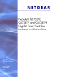
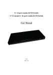
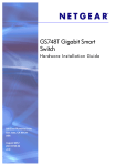
DRG488
User manual
Content
1.
DRG488 overview
2
2.
Installation of the DRG488
3
4.
Connecting the DRG488
5
Box content:
•
•
•
•
•
•
DRG488 product
Four (4) self-adhesive footpads
Two angle brackets
Six (6) screws
Power adapter
DRG488 user manual
1
1. DRG488 overview
5
User interfaces
Interface
Description
1
WAN port
2
Ethernet LAN ports
3
Power connector
4
SFP port
5
LAN LEDs
6
Power LED
7
Uplink LED
8
Reset pinhole
1
2
8
6
4
7
LED & button functionality
LED
Activity
Description
Reset Button
Description
Power
Green
Flashing
Red
Power is on and boot completed
DRG488 is booting
Hardware error
Reboot
Press reset button for less than
5 seconds and release to initiate
reset.
Uplink
Green
Yellow
1000M WAN link established*
100/10M WAN link established*
Factory
default
LAN
Green
Yellow
1000M link*
100/10M link*
Press and hold reset button for
more than 5 seconds (when LEDs
will blink) and release to initiate
a factory reset. All configuration
data will be lost!
*blink on activity
2
3
2. DRG488 installation
Step 1: Select a suitable location for the DRG
Before installing the DRG, ensure your working
environment meets the minimum operating requirements of the equipment.
Option A: Placing the DRG on your desktop
To protect any surface that the DRG is standing
on, there are four rubber pads that need to be
attached.
1.
Peel the protective paper from the rubber
pads to expose the adhesive side.
Between 0 and 45 degrees
Celcius
2.
Operating
Humidity
Max. relative humidity of 90%,
non-condensing
Press each of the pads on the bottom of the
DRG casing, as shown below.
3.
Place the DRG on your desktop
Ventilation
Minimum 10 centimeters on
all sides for cooling. If in a
closet, ensure there is adequate airflow.
Characteristics
Requirements
Temperature
Step 2: Placement options
The DRG488 installation kit provides parts that
allow you to place the DRG in various locations.
Select the procedure best suited to your operating
environment:
3
Option B: Mounting the DRG on the wall
To mount the DRG directly on a wall, ensure that
the location is not next to electrical power cables
or gas/water pipes.
Option C: Mounting the DRG with brackets
If the DRG is to be securely installed, for example
in a cabinet, angle brackets are supplied to mount
the DRG horizontally or vertically.
1.
Drill the necessary holes in the wall for supporting the DRG. The fixing-screw positions
are shown below. A drilling template is provided as separate download from the Genexis
website.
1.
Attach both angle brackets to the screw holes
on the side of the DRG488, using the supplied
screws.
2.
Insert and tighten the mounting screws in the
holes in the wall with the screw head approx.
2mm from the wall.
3.
Position the DRG in such a way that each
screw head is aligned with a mounting screw
hole.
4.
Push the DRG onto the screw heads and slide
gently downwards until the screws lock the
DRG firmly into position.
2.
Mount the DRG488 in the cabinet or on a
rack, using the appropriate screws.
PWR
Uplink
1
2
3
4
5
10/100/1000 Mbps
6
7
10/100/1000 Mbps
8
4
PWR
Uplink
1
2
3
4
5
6
7
8
3. Connecting the DRG488
Step 1: Connecting to the network
Depending on the way you would like to connect
the DRG488 to the broadband network (fiber SFP or
copper WAN), different cables are used.
Using the Copper uplink
Use a RJ-45 Cat 5e Ethernet cable to connect the
DRG488 to the broadband network socket by pushing the cable connector gently, but firmly into the
‘WAN’ port until it locks.
Using the SFP fiber uplink
Use a fiber patch cable to connect the DRG488 to
the broadband network by gently pushing the fiber
connector into the ‘SFP’ module (Ensure that an
MSA-compliant SFP module is properly installed in
the SFP port).
Step 3: Powering the DRG488
1.
2.
3.
Connect the power cable from the power
adapter (as delivered with the DRG488) to the
DRG ‘power’ port.
Connect the power adapter to a main power
outlet.
The power LED will now light up. The
power LED remains lit while the product is
connected.
Note:
If the power LED does not light up and there
is no obvious problem, please contact the
supplier of your network connection.
Step 2: Connecting a device to the DRG488
Locate a free Ethernet LAN port for your device (see
chapter 1) and push the RJ-45 Ethernet connector
of your device gently into the DRG488 LAN port
until it locks.
5
Europe-EU Declaration of Conformity
Hereby, Genexis BV declares that this product is in compliance
with the essential requirements and other relevant provisions
of Directive 1999/5/EC.
Copyright © Genexis BV 2014
rev.1