1
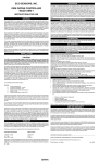
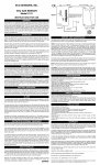
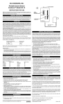
ECO SENSORS, INC.
GREEN LED
RED LED
Instrument receiving
power
“On” when ozone
concentration is
above set point
OZONE SWITCH™
Model OS-1X
INSTRUCTIONS FOR USE
GENERAL
The model OS-1X acts like a thermostat to control ozone generators and alarms based on an
adjustable ozone set-point. The standard available range is .03-.1. The design incorporates
hysteresis or a “dead band” to avoid system “chatter.” The SPDT relay contacts will handle up
to 5 amps at 250 volts or up to a 1/8 HP motor. The OS-1X should not be used outdoors or in
the presence of NOx, nitric acid, acid gases, or strong halogen fumes. Overnight warm-up is
recommended if the instrument hasn’t been powered for weeks.
AC ADAPTER
The instrument is conditionally warranted for one year. Save a copy of your purchase document
as a proof of purchase and date, and read the warranty statement at the end of this manual.
Allow 15 minutes warm-up before attempting to test the instrument and at least one hour
before using the instrument. Overnight warm-up is recommended if the instrument hasn’t
been powered for weeks.
MOUNTING HOLES
4.7 MM (3/16”) DIA.
73 MM (2 7/8”) CENTERS.
OPERATION
First, verify that the instrument is working as received. Connect your AC adapter to the power
jack or your 12-24 V DC supply to terminals 1 and 2 of the terminal block found on the inside
back of the instrument. Caution!: Many AC adapters and DC supplies deliver a higher voltage
than on the nameplate - “24 volts” can be 32 volts, etc. Verify that the voltage to the input does
not exceed 24 volts and that it is not AC. In either case, major damage to the instrument can
result. The green LED should light up. If it does not, this is a strong indication that the instrument
is not receiving the correct DC power. Be sure the polarity is correct and that the connections
are made.
It is recommended to test the instrument for positive response with an ozone generator when
the instrument is received and again at the site where the instrument is installed. Eco Sensors,
Inc. offers inexpensive battery-operated, hand-held ozone generators for test purposes.
Readjust the set-point if required. (See drawing on other side). It is not recommended to be
set below .03 ppm (30 ppb) because of many uncontrollable environmental influences below.03
ppm. The higher the set-point within allowable health limits, the fewer “false alarms.” The
”dead band” is the difference in ozone concentration between where the instrument “detects’
(red LED lights, relay switches) and where the relay switches back and the red LED goes out.
Going “on” is always at a higher ppm than returning to “off” in order to avoid system “chatter”
if an ozonator is being controlled. As shipped, the instrument has a dead band of less than
.01 ppm. Contact Eco Sensors for the procedures to make a larger dead band.
You can now connect the Ozone Switch™ to external devices such as an ozonator to be
controlled or an alarm circuit. Disconnect the power to the generator control wiring and the
DC power to the instrument while connecting the wiring. Bring the external wiring through the
top or bottom access holes of the instrument or the access hole in the back plate. Wire
generator control circuits only to terminals 3, 4 and 5 of the terminal block. Allow free airflow
in front of the instrument where there are fan holes. Otherwise, the calibration will be affected.
Also, do not leave oils, solvents, or greases on, in, or near the instrument. Their fumes can
cancel the instrument’s ozone responsiveness.
It is recommended to mount the instrument with the sensor facing down to avoid water and
dust getting into the sensor area and damaging the sensor. The sensor may also be squeeze
fitted into one of the two large back cover holes if you want the sensor to face into an air duct
via a hole made for it. See drawing on the reverse side of this manual.
CALIBRATION
The Ozone Switch™ is shipped from the factory calibrated to detect at .1 ppm. Lower values
than that are settable by the calibrated control found by opening the back cover. The calibration
should be within 20% over .03-.1 ppm. We do not recommend operating with a set-point for
detection below .03 ppm because too many chemical, atmospheric, and electronic variables
can collectively make lower set-points meaningless and unreliable. Also, many indoor
environments may have ozone levels of up to .03 ppm due to ozone in the outdoor air leaking
in, etc. The sensor is stable. If, however, it does ”drift”, the tendency usually is to more sensitivity
thereby effectively lowering the set-point. If the sensor fails (one of its internal wires break), it
will always be “high’ with the red LED on and the relay actuated. The calibration will also be
affected by greases, oils, solvents and other VOC generators in the area (sensitivity will
appear to be reduced), or by oxidizing chemicals such as acid gases (sensitivity will appear
to be increased). Note that the instrument should be recalibrated after changing the sensor
and at least annually. Rough-check of the instrument’s functionality should be made every
three months by presenting it with ozone and verifying that it detects. Our OG-2 Ozone Source
Calibrator is recommended for this.
DC POWER JACK
12-24 V. 200 MA CTR +
(Power can also be connected
by rear access terminal block)
OZONE SENSOR
(See other side of this
manual for alternate
mounting locations.)
SERVICE AND MAINTENANCE
Do not attempt to do board-level repairs yourself. This will void the warranty.
SENSOR - The sensor and the fan are the only components of the instrument that are likely
should be observed to see if it is responsive to changes in ozone level and if it detects at the
set level. This can be done with the Eco Sensors models OG-1 hand-held ozone generator or
OG-2 .1 ppm calibrator. Small variations can be compensated for by a calibration adjustment
or simple maintenance. Sensor replacement, however, requires an instrument technician
and should be done by Eco Sensors or its authorized service representative. The sensor
replacement is part number SE-6A. An OG-2 Calibrator will be needed for user replacement.
AC POWER ADAPTERS - The Ozone Switch™ will not operate properly if it is not receiving
12-24 V DC at 200 mA. Check your power supply circuit or AC adapter to ascertain that it is
“on” and is supplying the correct power. AC adapters can burn out during lightning strikes or
other electrical surges, but this is very unlikely that the Ozone Switch™ will completely fail
during such surges due to its extensive input power protection circuitry. Eco Sensors can
supply AC adapters for North America. Elsewhere, AC adapters should be purchased through
our distributors or locally, using specifications supplied by Eco Sensors.
SPECIFICATIONS
Sensor: Heated metal oxide semiconductor.
Standard operating range: .03-.1 ppm. .05-.1 ppm is the recommended set-point range.
Accuracy: 10-20% in the .05-.1 ppm range.
Response time: Within 10 seconds of when ozone reaches the sensor.
Temperature and humidity range: 65-90 deg F (18-32 deg C). See Precautions.
For indoor use only. 0-80% relative humidity.
Supply voltage required: 12-24 volts DC, 200 mA. Ground - .
Adapter plug: 5.5 mm/2.5 mm female, center +.
Relay contacts rating: SPDT non-latching, 5 amps, 250 volts AC, or 1/8 HP inductive load.
Terminal block: 20 amp rating, 12-22 AWG wire range.
Size: 3” x 2 1/2” x 1 5/8” (76 x 64 x 42 mm).
Weight: 5 oz. (140 grams).
Conformity: This product conforms to the European Community (CE) requirements for
emissions (EMI) and interference immunity.
SAFETY FEATURES
WARRANTY
Loss of power protection: relay opens (shuts off generator) when the instrument loses power.
This product is warranted against defects in materials and workmanship for one year following
the date of purchase by the original owner. This warranty does not include damage to the
product as a result of misuse, accident, damage, modifications or alterations, and it does not
apply if the instructions in this manual are not followed.
Enclosure: Flame retardant ABS, UL approved.
Relay: UL and CSA approved.
Electrical: (a) Circuits operate at 24 volts, 100 mA or less. (b) Power input circuitry includes
automatically resetting fuse, polarity reverse protection diode, and overvoltage protection
diode.
If a defect develops during the warranty period, Eco Sensors at its election will repair the
instrument or will replace it with a new or reconditioned model of equivalent quality. In the
event of replacement with a new or reconditioned model, the replacement unit will continue
the warranty of the original unit.
PRECAUTIONS
To return the instrument, contact your distributor, or call Eco Sensors at (800) 472-6626 or email to [email protected] to receive return instructions and a Return Authorization
(RGA) number.
• Allow at least 15 minutes warm-up for functionality testing, one hour warm-up for operations
testing, and overnight if the instrument hasnt’t been used in for weeks.
• Read all of the instructions in this manual.
• Keep the instrument dry. Never let water or other liquids into the sensor (which is just
behind the gas inlet).
• Do not drop the instrument or subject it to continuous vibration.
• Do not store or operate the instrument in high levels of dust.
• Operate the instrument in areas of normal room temperature. Operation at lower
temperatures, such as warehouses or refrigerated areas, should only be attempted after
testing in any particular environment for correct and reliable operation.
• Do not attempt to service the instrument yourself.
• Do not clean the instrument with cleaning chemicals or solvents. Clean it with a damp
cloth.
• Do not operate the instrument near heavy aerosols (spray) usage or where oxygen is
being administered.
• Call a qualified electrician if you have any doubts about voltage. When in doubt, operate
the instrument at least 24 hours in your worst case environmental condition to see if it will
operate properly in your conditions.
• Do not operate the instrument or rely on its reading where there are high concentrations
of:
• Chlorine or other halogen compounds
• Sulfer compounds
• Nitrides of nitrogen (NOx)
• Urine residues or ammonia compounds
• Acid gases such as sulfuric or nitric acid fumes
When in doubt, operate the instrument at least 24 hours in your worst case environmental
condition to see if it will operate properly.
Except as provided herein, Eco, Sensors makes no warranties, express or implied, including
warranties of merchantability and fitness for a particular purpose. Eco Sensors shall not be
liable for loss of use of this instrument or other incidental or consequential damages, expenses
or economic loss, or claims for such damage or economic loss.
This warranty gives you specific rights, and you may also have other rights, which vary from
state to state.
RECORD YOUR SERIAL NUMBER HERE __________________________________
KEEP THIS MANUAL AND WARRANTY FOR YOUR RECORDS.
Eco Sensors is a registered trademark of Eco Sensors, Inc.
Ozone Switch is a trademark of Eco Sensors, Inc.
© Eco Sensors, Inc., 2000. Revision 1. For OS-1X REV 1.
OZONE SWITCH WIRING
AC POWER
PLUGS INTO
ELECTRICAL BOX
ELECTRICAL BOX
OZONE GENERATOR
Set-Point Adjustment
50
TERMINAL BLOCK WIRING
Scale
PPM
0
0
10
TERMINAL BLOCK
Do Not Use Below 30 (.03 PPM)
30
.03
50
.05
100
.10
5
TERMINALS
CONNECTIONS
4-5
RELAY
NORMALLY CLOSED
3-4
RELAY
NORMALLY OPEN
1-2
DC POWER
(ALTERNATE TO POWER JACK)
4
3
+ 12-24 V
2
1
SUGGESTED WIRING
(ELECTRICAL BOX AND
OZONE GENERATOR ARE NOT
SUPPLIED BY ECO SENSORS)
OZONE SWITCH
(Back cover removed)
MOUNTING THE OZONE SWITCH ON DUCTS
AND EQUIPMENT CABINETS
OS-1X
WIRING
3/16” dia.
(4.7 mm)
THROU
GH SID
E
SENSOR
OR THROUGH
OTHER COVER HOLE
Hole should be .500 (12.5)
to easily allow clearance to
the sensor.
Air Duct, Equipment Cabinet, etc.
.750
(19.0)
SENSOR
Squeeze fit in
cover hole
1.438
(36.5)
approx. 1/16 - 1/8”
or 2 - 5 mm
CAUTION! Avoid excessive touching of
the inlet end of the sensor and keep it free
from chemicals, lubricants, dust, water, etc.
Do not use silicone caulking compound or
RTV near the sensor.
RECOMMENDED ACCESSORIES FOR THE OS-1X
OG-2 Ozone Source Calibrator
Precision UV lamp calibrated ozone source. Generates .1 ppm reference concentration. Battery operated.
Small and simple to use.
EE-2 Environmental Enclosure
For dust and water protection in industrial and agricultural environments and in public places. This enclosure
is 120 mm wide, 180 mm high, and 80 mm deep (5"x 7"x 3") with a clear polycarbonate gasketed front cover.
There are screened air inlets on the sides and an exhaust fan on the bottom. A 12 volt DC power jack
provides power to the instrument and fan inside.
More information about our products and applications at:
www.ecosensors.com