1
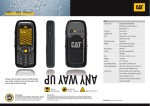
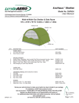
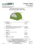
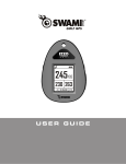
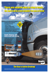
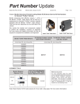
V4 Teleporter Bike Carrier
Part No. VME-V4
User Manual
Parts List
Description
Qty
(2) WingMan V2 Assemblies, containing:
WingMan Base Plate
2
Hat Brackets
4
Carriage Bolts & Hardware sets
8
Wing with Pads
4
Wire Lock Pin
4
Double Toggles
8
WingMan Assemblies
(8) Wheel Cradle Assemblies, containing:
Wheel Cradle
8
Toggle Balls
8
Hair Pin Clip
8
U-Clip
8
Teleporter Assembly, containing
Teleporter Shank Tube and Tilt Tube
1
Telescope Tube
1
Silent Hitch Pin® with Handle
1
Silent Hitch Pin®
1
Tilt Pin (black handle)
1
Safety Cable w/ Biner
1
Copyright © 2013 Let’s Go Aero, Inc.
Teleporter Assembly
VME-V4 - v1
V4 Teleporter Bike Rack
Assembly
Step 1: Installing the Teleporter Base
Position the Tilt Tube in the horizontal position and lock
into place with the black handled Tilt Pin. Lightly rub the
top and side surfaces of the Tilt Tube with the included
bar of parafin wax to ensure smooth telescoping action
and protect the surface of the tube.
Insert the Teleporter Shank in the hitch as shown with
the structural rise above the hitch. Attach using the
Silent Hitch Pin®, threading the Silent Hitch Pin® into
the pre-installed Spring Nut in the Shank Tube. Tighten
firmly with a 7/8” wrench. Apply pin clip.
Tilt Pin
Safey Cable
attachement
hole
Silent Hitch
Pin®
Tip: For added bumper clearance, move Spring Nut to
the other available shank hole and thread pin.
Slide the Telescope Tube onto the Tilt Tube and attach
using the Silent Hitch Pin® with Handle. Attach the
Safety Cable to the side plate with the caribiner.
IMPORTANT: For proper function in the hitch, Silent
Hitch Pin® must be tightened with a wrench to 30 ft.
lbs. - 60 ft. lbs.
Silent Hitch Pin® for Telescope
Tube location
Silent Hitch Pin® for hitch
location
Step 2: Mounting the WingMan Base Plates
Attach the front WingMan base to the Teleporter using the
5/16” hardware and Hat Brackets. Position the WingMan
base so it is touching the slide bumper at the front of the
Telescope Tube. Attach the telescope cable loop between
the forward Hat Bracket (vehicle side) and the WingMan
base as shown. Tighten hardware until snug or to 18 foot
pounds.
Install the rear WingMan base plate using 5/16” hardware
and Hat brackets near the end of the Telescope Tube.
Step 3: Assemble Wings
Slide Wings into the WingMan Base pockets and
secure the Wings to the Base with the Wire Lock
Pins.
VME-V4 - v1
Step 4: Attach Wheel Cradle Assembly
Determine the approximate center-to-center distance between the hubs of the bike wheels and
attach the wheel cradles to the Wings with the Hair
Pin Clips to match this distance.
V4 Teleporter Bike Rack
Operation
Securing Bicycles on Carrier
Set bike(s) on wheel cradles. Secure bike(s) to rack starting with the Wheel Toggles. Finish securing with the Double
Toggles. Telescope the rack away from the vehicle before loading the rack. Load bikes, starting with the inner-most
position (closest to the vehicle). Slowly move the carrier into the non-telescoped, slid-in position and secure the Handle
Silent Hitch Pin® before transit.
Loading TIP: Load bicycle onto the carrier with the bicycle chain facing outward from the Wings and the inside pedal positioned
downward. This helps keep chain lube off the carrier, and provides open space in the lower, center portion of the “V” for the
inside pedal(s) to fit easily. Load the second bike so its handle bars face in the opposite direction of the first bicycle for clearance.
Double Toggles TIP: The Double Toggles provide a number of ways to achieve Constant Tension™ of your bicycle to the carrier,
using one or both double toggles to capture the fork, chain stay, or seat stay. Loop the Toggle over the pedal, crank, or other
position on bicycle, allowing the elastic feature to pull the bike both down and inward against the Wing pads. The Constant Tension™ removes both “front to back” and “side-to-side” sway, firmly seating the bicycle during transit.
V4 Teleporter Tilt Positioning
When the rack is not in use, the Teleporter can be placed
in the tilted position in order to reduce the distance the
rack extends from the vehicle. Remove the Wings from
the Base Plate prior to tilting the Teleporter. Remove the
Tilt Pin, move the Teleporter to the tilt-up position and
reinsert the Tilt Pin.
The Telescope Tube can be removed and flipped upside
down in order to provide rear vehicle liftgate access for
most vehicles while the Teleporter is in the tilted position.
Ensuring the Tilt Pin is Snug
Verify the Tilt Pin is snug by observing it pulling the side
plates together against the Telescope Tube prior to use.
When the Tilt Pin is snug, the spring tension of the Side
plates keeps the Tilt Pin tight. Use a 3/4” wrench or appropriate tool to tighten the Tilt Pin if necessary.
VME-V4 - v1
Side Plates
Snug
V4™ Bike Rack
Before Transit:
Attempt to shake the carrier to verify the carriage bolts, Tilt Pin, Silent Hitch Pin® with Handle and Silent Hitch Pin® are tight.
Verify the Toggles are securing your bicycles wheels and frame to the carrier as explained earlier.
Verify that the safety pins are indeed locking the Wings to the Base Pockets.
V4 TELEPORTER RACK GUIDELINES
The V4 Teleporter bicycle carrier’s maximum load weight is 180 lbs. Do not exceed this carrying capacity.
NEVER drive your vehicle with the Teleporter in the Telescoped position. Always secure rack using the Silent Hitch Pin® with
Handle before transit.
Always make sure the Safety Cable is attached and the Silent Hitch Pins® are securely engaged before transit. A wrench
MUST be used to tighten the HexHead Silent Hitch Pin® at the hitch receiver. Tighten the Silent Hitch Pin to 30 ft. lbs- 60 ft. lbs
of torque (equivalent to tightening a lug nut on a car wheel).
The Safety Cable should always be attached when using the V4 Teleporter in order to prevent the V4 from sliding off the Tilt
Tube when telescoping the V4 Teleporter and to prevent the Safety Cable from dragging on the ground while in transit.
Do not use this rack and accessories for purposes other than those for which they were designed. Failure to follow the
guidelines of the product’s instructions will void the warranty.
ONE-YEAR LIMITED WARRANTY
We warrant all LGA brand rack systems and its accessories manufactured by LGA during the time that an original retail
purchaser owns the product. This warranty terminates if a purchaser transfers the product to any other person.
Let’s Go Aero warrants this product to be free from defect in material and workmanship for one year (retain your sales receipt
for your records). Any product or part thereof found to be defective within that period will be replaced without charge provided
that: (1) the product was not misused; (2) no alterations or modifications were made; (3) its failure was not a result of normal
wear expected in the use of the product; (4) the product or part is delivered, freight prepaid, to Let’s Go Aero.
Manufacturers only obligation shall be to replace such products or parts proved to be defective. A Return Merchandise
Authorization is required prior to return. Please contact Let’s Go Aero toll-free, at 877-464-2376 or 719-630-3800, or via email
to [email protected] to get an RMA number.
No warranty is given for LGA products purchased outside of the United States and Canada.
US Patent No : D684917; 6,409,203; 6,609,725; 6,945,550; 8,079,613
For Customer Service, contact Let’s Go Aero:
Mail:
3380 N. El Paso Street, Colorado Springs, CO 80907
Phone: 877-464-2376 or 719-630-3800
Email: [email protected].
Learn about our line of trailers, hitch carriers. and other cargo
management solutions at www.LetsGoAero.com
VME-V4 - v1