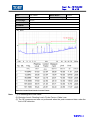
1
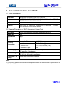
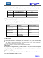
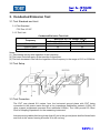
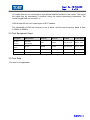
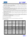
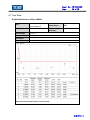
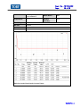
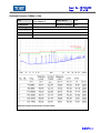
Shenzhen Toby Technology Co., Ltd. Report No.: TB-FCC144092 Page: 1 of 19 FCC Radio Test Report FCC ID: 2AEMC-BM1 Original Grant Report No. : TB-FCC143356 Applicant : BIOMEDIS TECHNOLOGIES CO.,LIMITED Equipment Under Test (EUT) EUT Name : Device for generating modulated signals BIOMEDIS M Model No. : BM1 Brand Name : N/A Receipt Date : 2015-04-22 Test Date : 2015-05-04 Issue Date : 2015-05-05 Standards : FCC Part 15, Subpart C: 2014 Test Method : ANSI C63.10: 2013 Conclusions : PASS In the configuration tested, the EUT complied with the standards specified above, The EUT technically complies with the FCC requirements Test/Witness Engineer : Approved& Authorized : This report details the results of the testing carried out on one sample. The results contained in this test report do not relate to other samples of the same product. The manufacturer should ensure that all products in series production are in conformity with the product sample detailed in the report. TB-RF-074-1.0 1A/F., Bldg.6, Yusheng Industrial Zone, The National Road No.107 Xixiang Section 467, Xixiang, Bao’an, Shenzhen, China Tel: +86 75526509301 Fax: +86 75526509195 Report No.: TB-FCC144092 Page: 2 of 19 Contents CONTENTS............................................................................................................................................. 2 1. GENERAL INFORMATION ABOUT EUT ............................................................................. 3 1.1 Client Information ................................................................................................................. 3 1.2 General Description of EUT (Equipment Under Test) ................................................... 3 1.3 Block Diagram Showing the Configuration of System Tested ...................................... 4 1.4 Description of Support Units .............................................................................................. 4 1.5 Description of Test Mode .................................................................................................... 4 1.6 Description of Test Software Setting ................................................................................ 4 1.7 Measurement Uncertainty .................................................................................................. 5 1.8 Test Facility ........................................................................................................................ 5 2. TEST SUMMARY ....................................................................................................................... 7 3. CONDUCTED EMISSION TEST ............................................................................................. 8 3.1 Test Standard and Limit ...................................................................................................... 8 3.2 Test Setup ............................................................................................................................. 8 3.3 Test Procedure ..................................................................................................................... 8 3.4 Test Equipment Used .......................................................................................................... 9 3.5 Test Data ............................................................................................................................... 9 4. RADIATED EMISSION TEST ................................................................................................ 12 4.1 Test Standard and Limit .................................................................................................... 12 4.2 Test Setup ........................................................................................................................... 12 4.3 Test Procedure ................................................................................................................... 13 4.4 EUT Operating Condition ................................................................................................. 14 4.5 Test Equipment .................................................................................................................. 14 4.7 Test Data ............................................................................................................................. 15 Radiated Emission Bellow 1 GHz .......................................................................................... 17 5. ANTENNA REQUIREMENT................................................................................................... 19 5.1 Standard Requirement ...................................................................................................... 19 5.2 Antenna Connected Construction ................................................................................... 19 5.3 Result ................................................................................................................................... 19 TB-RF-074-1.0 Report No.: TB-FCC144092 Page: 3 of 19 1. General Information about EUT 1.1 Client Information Applicant : BIOMEDIS TECHNOLOGIES CO.,LIMITED Address : UNIT E223, 3/F WING TAT COMM BLDG 97 BONHAM STRAND EAST SHEUNG WAN HONG KONG Manufacturer : BIOMEDIS TECHNOLOGIES CO.,LIMITED Address : UNIT E223, 3/F WING TAT COMM BLDG 97 BONHAM STRAND EAST SHEUNG WAN HONG KONG 1.2 General Description of EUT (Equipment Under Test) EUT Name : Device for generating modulated signals BIOMEDIS M Models No. : N/A Brand Name : BM1 Model Difference : N/A Product Description : Operation Frequency: 24.00 MHz Out Power: 58.60 dBuV/m@3m Antenna Gain: PCB Loop Antenna (0 dBi) Modulation Type: AM : DC Voltage supplied from PC System by USB Cable. DC power by Li-ion battery Power Rating : USB DC 5V DC 3.7V by 300 mAh Li-ion Battery. Connecting I/O : Please refer to the User's Manual Port(S) Power Supply Note: (1) For a more detailed features description, please refer to the manufacturer’s specifications or the User’s Manual. TB-RF-074-1.0 Report No.: TB-FCC144092 Page: 4 of 19 1.3 Block Diagram Showing the Configuration of System Tested EUT 1.4 Description of Support Units The EUT has been tested as an independent unit. 1.5 Description of Test Mode To investigate the maximum EMI emission characteristics generates from EUT, the test system was pre-scanning tested base on the consideration of following EUT operation mode or test configuration mode which possible have effect on EMI emission level. Each of these EUT operation mode(s) or test configuration mode(s) mentioned follow was evaluated respectively. Test Items Note Radiated Emission Continuously transmitting Bandwidth Continuously transmitting Duty Cycle Continuously transmitting Note: (1) During the testing procedure, the continuously transmitting mode was programmed by the customer. (2) The EUT is considered a portable unit, and it was pre-tested on the positioned of each 3 axis: X axis, Y axis and Z axis. The worst case was found positioned on X-plane. There for only the test data of this X-plane were used for radiated emission measurement test. 1.6 Description of Test Software Setting During testing channel& Power controlling software provided by the customer was used to TB-RF-074-1.0 Report No.: TB-FCC144092 Page: 5 of 19 control the operating channel as well as the output power level. The RF output power selection is for the setting of RF output power expected by the customer and is going to be fixed on the firmware of the final end product power parameters of transmitting mode. 1 Product SW/HW Version : N/A 2 Radio SW/HW Version: N/A 3 Test SW Version: N/A 4 RF Power Setting in Test SW: DEF 1.7 Measurement Uncertainty The reported uncertainty of measurement y ± U,where expended uncertainty U is based on a standard uncertainty multiplied by a coverage factor of k=2 , providing a level of confidence of approximately 95 %. Test Item Parameters Expanded Uncertainty (ULab) Conducted Emission Level Accuracy: 9kHz~150kHz 150kHz to 30MHz ±3.42 dB ±3.42 dB Radiated Emission Level Accuracy: 9kHz to 30 MHz ±4.60 dB Radiated Emission Level Accuracy: 30MHz to 1000 MHz ±4.40 dB Radiated Emission Level Accuracy: Above 1000MHz ±4.20 dB 1.8 Test Facility The testing was performed by the Shenzhen Toby Technology Co., Ltd., in their facilities located at: 1A/F., Bldg.6, Yusheng Industrial Zone, The National Road No.107 Xixiang Section 467, Xixiang, Bao’an, Shenzhen, Guangdong, China. At the time of testing, the following bodies accredited the Laboratory: CNAS (L5813) The Laboratory has been accredited by CNAS to ISO/IEC 17025: 2005 General Requirements for the Competence of Testing and Calibration Laboratories for the competence in the field of testing. And the Registration No.: CNAS L5813. FCC List No.: (811562) The Laboratory is listed in the United States of American Federal Communications Commission (FCC), and the registration number is 811562. TB-RF-074-1.0 Report No.: TB-FCC144092 Page: 6 of 19 IC Registration No.: (11950A-1) The Laboratory has been registered by Certification and Engineering Bureau of Industry Canada for radio equipment testing. The site registration: Site# 11950A-1. TB-RF-074-1.0 Report No.: TB-FCC144092 Page: 7 of 19 2. Test Summary FCC Part 15 Subpart C Standard Section Test Item Judgment 15.203 Antenna Requirement PASS 15.207 Conducted Emission PASS 15.209 Radiation Emission PASS Remark Note: N/A is an abbreviation for Not Applicable. TB-RF-074-1.0 Report No.: TB-FCC144092 Page: 8 of 19 3. Conducted Emission Test 3.1 Test Standard and Limit 3.1.1Test Standard FCC Part 15.207 3.1.2 Test Limit Conducted Emission Test Limit Maximum RF Line Voltage (dBV) Frequency Quasi-peak Level Average Level 150kHz~500kHz 66 ~ 56 * 56 ~ 46 * 500kHz~5MHz 56 46 5MHz~30MHz 60 50 Notes: (1) *Decreasing linearly with logarithm of the frequency. (2) The lower limit shall apply at the transition frequencies. (3) The limit decrease in line with the logarithm of the frequency in the range of 0.15 to 0.50MHz. 3.2 Test Setup 3.3 Test Procedure The EUT was placed 0.8 meters from the horizontal ground plane with EUT being connected to the power mains through a line impedance stabilization network (LISN). All other support equipments powered from additional LISN(s). The LISN provide 50 Ohm/ 50uH of coupling impedance for the measuring instrument. Interconnecting cables that hang closer than 40 cm to the ground plane shall be folded back and forth in the center forming a bundle 30 to 40 cm long. TB-RF-074-1.0 Report No.: TB-FCC144092 Page: 9 of 19 I/O cables that are not connected to a peripheral shall be bundled in the center. The end of the cable may be terminated, if required, using the correct terminating impedance. The overall length shall not exceed 1 m. LISN at least 80 cm from nearest part of EUT chassis. The bandwidth of EMI test receiver is set at 9kHz, and the test frequency band is from 0.15MHz to 30MHz. 3.4 Test Equipment Used Description Manufacturer Model No. Serial No. EMI Test ROHDE& Receiver SCHWARZ ESCI 100321 Aug. 08, 2014 Aug.07, 2015 Anritsu MP59B X10321 Aug. 08, 2014 Aug.07, 2015 L.I.S.N Rohde & Schwarz ENV216 101131 Aug. 08, 2014 Aug.07, 2015 L.I.S.N SCHWARZBECK NNBL 8226-2 8226-2/164 Aug. 08, 2014 Aug.07, 2015 50ΩCoaxial Switch Cal. Date Cal. Due Date 3.5 Test Data The test is not applicable. TB-RF-074-1.0 Report No.: TB-FCC144092 Page: 10 of 19 EUT: Device for generating modulated signals BIOMEDIS M Model Name : BM1 Relative Humidity: 55% Temperature: 25 ℃ Test Voltage: AC 120V/60Hz Terminal: Line Test Mode: TX 24.00MHz Remark: Only worse case is reported Emission Level= Read Level+ Correct Factor TB-RF-074-1.0 Report No.: TB-FCC144092 Page: 11 of 19 EUT: Device for generating modulated signals BIOMEDIS M Model Name : BM1 Relative Humidity: 55% Temperature: 25 ℃ Test Voltage: AC 120V/60Hz Terminal: Neutral Test Mode: TX 24.00MHz Remark: Only worse case is reported Emission Level= Read Level+ Correct Factor TB-RF-074-1.0 Report No.: TB-FCC144092 Page: 12 of 19 4. Radiated Emission Test 4.1 Test Standard and Limit 4.1.1 Test Standard FCC Part 15.209 4.1.2 Test Limit (1) The maximum permitted unwanted emissions level is 20 dB below the maximum permitted fundamental level. In addition field strength of any emissions which appear inside of the restriction band shall not exceed the general radiated emissions limits in Section 15.209(a). Frequency (MHz) 0.009~0.490 Field Strength (microvolt/meter) 2400/F(KHz) Measurement Distance (meters) 300 0.490~1.705 2400/F(KHz) 30 1.705~30.0 30 30 30~88 100 3 88~216 150 3 216~960 200 3 Above 960 500 3 Note: (1) The tighter limit applies at the band edges. (2) Emission Level(dBuV/m)=20log Emission Level(uV/m) 4.2 Test Setup Bellow 30MHz Test Setup TB-RF-074-1.0 Report No.: TB-FCC144092 Page: 13 of 19 Bellow 1000MHz Test Setup Above 1GHz Test Setup 4.3 Test Procedure (1) The measuring distance of 3m shall be used for measurements at frequency up to 1GHz. The EUT was placed on a rotating 0.8m high above the ground, the table was rotated 360 degrees to determine the position of the highest radiation. (2) Measurements at frequency above 1GHz. The EUT was placed on a rotating 1.5m high above the ground. RF absorbers covered the ground plane with a minimum area of 3.0m by TB-RF-074-1.0 Report No.: TB-FCC144092 Page: 14 of 19 3.0m between the EUT and measurement receiver antenna. The RF absorber shall not exceed 30cm in high above the conducting floor. The table was rotated 360 degrees to determine the position of the highest radiation. (3) The Test antenna shall vary between 1m and 4m, Both Horizontal and Vertical antenna are set to make measurement. (4) The initial step in collecting conducted emission data is a spectrum analyzer peak detector mode pre-scanning the measurement frequency range. Significant peaks are then marked and then Quasi Peak detector mode re-measured. (5) If the Peak Mode measured value compliance with and lower than Quasi Peak Mode Limit Bellow 1 GHz, the EUT shall be deemed to meet QP Limits and then no additional QP Mode measurement performed. But the Peak Value and average value both need to comply with applicable limit above 1 GHz. (6) Testing frequency range below 1GHz the measuring instrument use VBW=120 kHz with Quasi-peak detection. (7) Testing frequency range above 1GHz the measuring instrument use RBW=1 MHz and VBW=3 MHz with Peak Detector for Peak Values, and use RBW=1 MHz and VBW=10 Hz with Peak Detector for Average Values. (8) For the actual test configuration, please see the test setup photo. 4.4 EUT Operating Condition The Equipment Under Test was set to Continual Transmitting in maximum power. 4.5 Test Equipment Equipment Spectrum Manufacturer Model No. Serial No. Last Cal. Cal. Due Date Agilent E4407B MY45106456 Aug. 08, 2014 Aug.07, 2015 Rohde & Schwarz FSP30 DE25181 Aug. 08, 2014 Aug.07, 2015 Rohde & Schwarz ESCI 101165 Aug. 08, 2014 Aug.07, 2015 Bilog Antenna ETS-LINDGREN 3142E 00117537 Mar. 06, 2015 Mar.05, 2016 Horn Antenna ETS-LINDGREN 3117 00143207 Mar. 06, 2015 Mar.05, 2016 Pre-amplifier HP 11909A 185903 Mar. 06, 2015 Mar.05, 2016 Pre-amplifier HP 8447B 3008A00849 Mar. 06, 2015 Mar.05, 2016 Cable HUBER+SUHNER 100 SUCOFLEX Mar. 06, 2015 Mar.05, 2016 Rohde & Schwarz SML03 IKW682-054 Feb. 10, 2015 Feb.09, 2016 ETS-LINDGREN 2090 N/A Laplace Instrument RF300 EMC0701 Analyzer Spectrum Analyzer EMI Test Receiver Signal Generator Positioning Controller Loop Antenna N/A Aug. 12, 2014 N/A Aug. 11, 2015 TB-RF-074-1.0 Report No.: TB-FCC144092 Page: 15 of 19 4.7 Test Data Radiated Emissions (9kHz~30MHz) EUT: Device for generating modulated signals BIOMEDIS M Temperature: 25 ℃ Test Voltage: DC 3.7V Ant. Pol. Horizontal Test Mode: TX 24.00 MHz Model Name : BM1 Relative Humidity: 55% Remark: Emission Level= Read Level+ Correct Factor TB-RF-074-1.0 Report No.: TB-FCC144092 Page: 16 of 19 EUT: Device for generating modulated signals BIOMEDIS M Temperature: 25 ℃ Test Voltage: DC 3.7V Ant. Pol. Vertical Test Mode: TX 24.00 MHz Model Name : BM1 Relative Humidity: 55% Remark: Emission Level= Read Level+ Correct Factor TB-RF-074-1.0 Report No.: TB-FCC144092 Page: 17 of 19 Radiated Emission 30MHz~1 GHz EUT: Device for generating modulated signals BIOMEDIS M Temperature: 25 ℃ Test Voltage: DC 3.7V Ant. Pol. Horizontal Test Mode: TX 24.00 MHz Model Name : BM1 Relative Humidity: 55% Remark: Emission Level= Read Level+ Correct Factor TB-RF-074-1.0 Report No.: TB-FCC144092 Page: 18 of 19 EUT: Fish Finder Model Name : FF518 Temperature: 25 ℃ Relative Humidity: 55% Test Voltage: DC 3V Ant. Pol. Vertical Test Mode: TX 24.00 MHz Remark: Emission Level= Read Level+ Correct Factor Note: (1) All Readings are Peak Value. (2) Emission Level= Reading Level+ Probe Factor +Cable Loss (3) The QP measurement was not performed when the peak measured data under the limit of QP detection. TB-RF-074-1.0 Report No.: TB-FCC144092 Page: 19 of 19 5. Antenna Requirement 5.1 Standard Requirement 5.1.1 Standard FCC Part 15.203 5.1.2 Requirement An intentional radiator shall be designed to ensure that no antenna other than that furnished by the responsible party shall be used with the device. The use of a permanently attached antenna or of an antenna that uses a unique coupling to the intentional radiator shall be considered sufficient to comply with the provisions of this Section. The manufacturer may design the unit so that a broken antenna can be replaced by the user, but the use of a standard antenna jack or electrical connector is prohibited. 5.2 Antenna Connected Construction The directional gains of the antenna used for transmitting is 0 dBi, and the antenna connector is de-signed with permanent attachment and no consideration of replacement. Please see the EUT photo for details. 5.3 Result The EUT antenna is a Integral Antenna. It complies with the standard requirement. Antenna Type Permanent attached antenna Unique connector antenna Professional installation antenna TB-RF-074-1.0