1
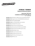
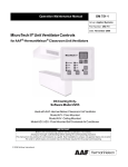
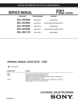
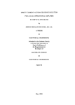
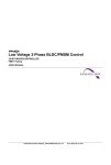
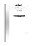
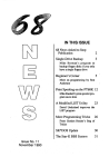
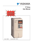
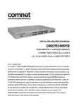
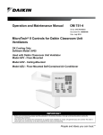
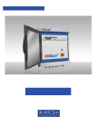
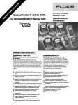
G7/E7/F7/P7/G5/P5/PS5 Drive Simulator
User Manual
Models: UUX000166
Document Number: TM.AFD.07.Simulator
Figure 1: Simulator unit with no control card installed
1. Introduction:
This control board tester and variable-power-factor load emulator allows the user to test all the basic and advanced
functions of above mentioned control cards without any need for actual drive power supply sections, motor stand, load
stand and power stages.
All of the required signals to operate the cards are simulated through DC and AC voltages and currents, adjustable by
potentiometers and switches. LED’s for digital and VU meters for analog signals monitor all the control and user
outputs. Yet all the signals are provided at test points for external access. PC serial 9-pin connector can be routed to
card’s RS232, RS485 or RS422 ports through on board converters. Two master-slave PG emulators are capable of
emulating wide PPR range of encoders. A true three-phase on-board emulator can simulate induction motors with
adjustable load and power factor for both 2 and 3 level drives. A current-limited pulse reference generator can provide
adjustable amplitude and frequency independently. An automatic power recycling circuit reboots the control card
safely, with feedback. Bipolar I/O references, active current source, external access port, supply voltage monitors, and
capability of supporting a very wide range of control cards are also provided.
TM.AFD.Simulator Page 2
Please note that this equipment is intended for qualified engineering personnel only, familiar with Yaskawa Drives and
technical principles of variable speed AC drives and/or software engineering.
2. Features and Applications:
•
CASE development: As this unit provides all the digital and analog I/O available in the control cards with the
monitoring and measurement capabilities, it will be ideal for any level of CASE design and verification.
•
Firmware development: In addition to the general I/O, different emulators provide reference, feedback, load
and power factor virtual signals for the firmware designer to test under the most realistic environment, even
for different PWM index implementations.
•
Drive application engineering: Versatile communication routers, loading emulators, reference and feedback
encoders and generators capabilities, in addition to I/O handling and easy-access test points, will make it ideal
for application verifications and testing.
•
Wizard software and utilities development and testing: In addition to all the above, External Access/PLC
port-EAP opens a gate to automatic repetitive tests, usually required for communication software
verifications. The manual or externally controlled automatic power recycling is another unique feature to help
out the software test and development engineers.
•
Hardware Development: The realistic physical environment, access to all ports and signals, easy access test
points, measurement and monitoring features, actual PWM signal outputs, dual encoder emulations and
extensive test points and EAP, will all be the ultimate platform for hardware development.
•
Cross Referencing of different drive generations: In order to compare drives performances for an application
or even having all the above features for other old or new drives, their control cards can easily be tested on
this unit through cable adaptors. Therefore it can replace most of the present or even future test units.
•
Automatic Test Setup: Almost all the hardware and software platforms, options, extensions, communication
protocols and controls, Wizard tools and Test tools can be either implemented for production or tested during
their development phases.
Figure 2: Simulator with G7 control card installed and running under simulated load
TM.AFD.Simulator Page 3
3. Precautions:
•
This unit is designed for office/lab environment and not for harsh industrial conditions. Also as an openchassis electrical system, all the usual precautions for these devices are expected accordingly. Any conductive
liquid spills, tool drops, wiring shortages, heavy physical blows or extensive electrostatic discharges can
cause damage to it and/or its connected accessories. However due to the applied precautions in its design,
these damages might be very limited and easily repairable while other modules keep on functioning properly.
•
There is no level of electrical isolation in this unit and as soon as any control card gets connected to this unit,
it loses its isolation barriers. This is for ease of operation, probing, lowering the costs, etc. This is done as to
the application and purpose of the unit, which is not definitely industrial control. There are only two
isolated/unregulated IP5/IG5 and IP12/IG12 voltage sources, accessible through test points on J1. Only
mounting I/O terminal cards and providing external 24VDC/AC level commands, will revive this isolation.
•
The external access port-EAP pins are all protected against static and dynamic HV/HC/HF interferences but
still applying wrong signals or shorting might interfere with the unit logic and cause invalid reactions and/or
readings. Please refer to this manual for the appropriate probing and signal applications for each pin.
•
The power supply pins provided to the user at J1 test points and J8-EAP, are all current-limited to 80mA.
Any loading more than 100mA, may cause damage to the protective current-limiting resistors and the unit.
•
There are no high voltages above 24VDC present on this unit anywhere except the components and power
supply module inside the grounded chassis, which carry the Mains voltage. Care should be taken to use the
provided grounded AC-cord and outlets in order to have full ground protection of the unit.
•
Control cards G7/E7/F7 and G5/PS5 have their own connector on the unit. Please refer to the labels next to
each connector, before doing any wiring to the control cards (G7/E7/F7 to J9 and G5/PS5 to J10). Depending
on their screw hole positions, you can use the provided spacers to mount them on the unit.
Figure 3: Simulator with E7 I/O card installed
TM.AFD.Simulator Page 4
4. Initial Switches and Potentiometers Settings:
•
Default positions for switches and pots to minimize the faults on the connected control cards:
SWITCH
S1-S12
S21
S22-S24
S19 & S20
S14 & S16
S13
S15
S17
S18
S38
S35
S32
S28
S26 & S30
S25 & S29
S27 & S31
S36
Potentiometer
VR1-VR3
VR10
VR12
VR11
VR6
VR7
VR8 and VR9
VR4
VR5
TOP
MIDDLE
X
BOTTOM
X
X
X
Set Toward Internal Sources only.
X
X
X
X
X
X
Set to Low Inductance position for most cases.
X
X
X
First position only ON for 32PPR.
Set as to control card’s Power ratings in O2-04*
Leftmost
Middle
X
Rightmost
X
X
X**
X
X
X
X
X
X
* Please note that when mounting a control card to the unit, in order to keep all the settings inside control card
unchanged, you might need to try every single setting of S36 and recycle the power each time by S37 push button, to
check which code matches with the control card’s. This will take about 1 minute at the worst case.
** VR11 will cause OV or UV faults, when rotated toward left or right ends. Please adjust it around the middle until
the faults go away automatically.
Figure 4: Simulator with G5/P5/PS5 control card installed
TM.AFD.Simulator Page 5
5. Module Description and Usage Guide:
•
User I/O terminal:
1. Digital inputs: middle-positioned toggle switches ON/EXT/OFF S1-S12.
2. Digital outputs: Four green (D19-D22) and two red LED’s (D23 and D24).
3. Analog inputs: 0-10V/±10V or external for AIN1 and AIN3. 4-20mA for AIN2.
VR1 is A1, VR2 is A2 and VR3 is A3. The reference voltage will be selected through S21 from
10V, ±10V and External.
4. Analog outputs: Two 10-LED displays, U31, U33 with negative-sign LED’s, D140 and D141
will monitor the AM and FM outputs in almost ±1V steps.
•
Pulse generator module:
1. Amplitude: adjustable through VR5 between 0-22V
2. Current: Limited and short-circuit protected at 25mA dynamically
3. Frequency: Adjustable through VR4 between approx. 15Hz-25kHz
•
Communication module:
1. RS-232, RS-485 and RS-422 standards and voltage levels are supported.
2. RS-422/RS-485 flow control selectable between internal or RTS signal through S14-position1
switch (internal is RS422 and external is RS485 through RS232).
3. Four LED’s, D13-D16 monitor all the transmission and reception activities.
4. Connectors: RJ-45 for Keypad, DB9 for RS-232 and Header for RS422/485 (J4 to connect to
control-board’s keypad connector, J5 for PC, J3 for keypad, J2 for user I/O-RS422/485)
5. Routing: Through S38 (RS422/485: PC-RS232 will be routed/converted to RS422 of the drive
and keypad will be routed to control card’s keypad port, MEMACCESS: PC-RS232 will be
routed to control card’s keypad port and keypad will be disconnected, MEMFLASH: PC-RS232
will be routed to control card’s keypad port in FLASH mode and keypad will be disconnected).
6. In communication router switch (S38) mode of “RS-422/485”, the connected PC through its RS232 will be also able to participate as a RS-485 network participant. Therefore, flow control will
be through its RTS pin and accessible through S14/1 switch, set to “External”. Also the related
parameter in the drive should be set accordingly (H5-07Å1) for the network-side flow control.
Note: The unit in this mode does not compromise the network/drive isolation, as the control
card’s link to network will be differential anyway.
•
Power supply module:
1. Voltages available:
±15VDC, 24VDC, 5VDC, IP5VDC (10V-unregulated),
IP12VDC (19V-unregulated/unloaded), IP24VDC (26V-unregulated/unloaded)
2. All supplies monitored by LED’s D56-D59, D31-D33.
3. Power Recycle: Manually (through push button S37 -Power Recycle) and externally (through
EAP-External Access Port) recycled and monitored toward the control card, in almost 1 second.
The ready signal will be also generated and available to EAP after 2 seconds for automatic
testing purposes. LED’s D148 (READY) and D151 (R5V) monitor the whole recycling process
either way. Please note that this feature is exactly like recycling the main power switch of the
unit with exactly same functionality and effect.
4. Current available to external devices is limited at less than 50mA for all supplies. Please refer to
the pin-array on the left side of the unit.
•
Dual Encoder emulator module:
1. PG-I is assumed to be the slave motor encoder and PG-II, the master motor encoder. However
they are independently interchangeable based on application.
2. Logic level: 5V-TTL differential
3. Max frequency: Approx. 25Hz to 44kHz separately adjustable and range-selectable through
VR8, VR9 and S28 (25Hz-44kHz, 250Hz-44kHz and 2.5kHz-44kHz).
4. Signal format: 90°-Phase-shifted, quadrature, differential A/~A, B/~B, C/~C
TM.AFD.Simulator Page 6
5.
6.
7.
8.
9.
Loading: 20mA max each channel
Direction of rotation is controlled by slide switches: S25 and S29 as CW/OFF/CCW.
Clock source: Selectable from internal generators, control card’s pulse output (for PG-I only),
external source or PG-I (for PG-II only) through S26 and S30.
The ratio between input clock to output encoder frequency is 2:1.
Pulse per Revolution: Each encoder’s PPR can be set by S27 and S31 to values of 32, 64, 512,
1024, 2048, 4096 and 8192 PPR. One switch position at all times should be on only otherwise
the smallest ratio would become the PPR anyway.
•
Load Emulator module:
1. Load Inductance range: Adjustable through S32 for most carrier frequencies
2. Inductance tuning: 0.1 to 0.99 for most carrier frequencies through VR6
3. Carrier frequency support: 400Hz-15kHz from the control card
4. Multi-level PWM: Two and three level topologies, and floating through S35.
5. Load current signal: Fully adjustable between 0-200% through VR7
6. IUVW (=IU+IV+IW) output for ground current measurements at J1 monitors. This signal is an
exact emulation to the one generated inside the control card for threshold testing purposes
7. PWM Monitoring: Twelve 2-level-phase-leg positioned LED’s for both 2 or 3 level fire-pulse
PWM signals, 2-levels are red and 1-levels are green, D1-D12.
8. Output signal access: Selectable through S22, S23, S24 (Internal/OFF/External)
9. PWM outputs loading: 0-10Vrms at 500 Ohms minimum load impedance
•
Control I/O and External Access Port (EAP):
1. All the control-side analog inputs are selectable between internal and external sources at EAP
through S16.
2. All the control-side digital I/O’s are selectable between internal and external sources at EAP
through S13 to S18.
3. MCON and BTRA signals have Auto/Off/On modes through S19 and S20.
4. VCLL, VCHL, VCFL/SCL, FUL signals have High/Low/External modes through S13, S15,
S17 and S18.
5. Digital outputs routed to EAP, are all open collector/24V/40mA-max.
6. All the digital inputs are 5V-TTL except “MCOPL”, being 24V/2mA.
7. Analog inputs to the control card:
-“THM”: 0-5VDC (internally through VR10)
-“VDET: -10VDC-0VDC (internally through VR11)
-“CUV”: 3.3VDC-5VDC (internally through VR12)
•
US_CODE module:
1. Selectable between internal HEX-rotary switch S36 and EAP through S14.
2. Format: 5V-TTL inputs from EAP, low-active/negative-logic.
•
Test Points Connector J1:
1. Connector: Single-row header, .100” pitch, 40-pins
2. Loading: All short-circuit protected, measurement impedance 10kOhm-min. See Note 1.
3. Available Signals: All the signals at this connector are outputs except one, Pin 38, PGCKIN.
All the signals in detail are described in the next page table 1.
TM.AFD.Simulator Page 7
Pin
1
2
3
4
5
6
7
8
9
10
11
12
13
14
15
16
17
18
19
20
21
22
23
24
25
26
27
28
29
30
31
32
33
34
35
36
37
38
39
40
Label
IU_OUT
IV_OUT
IW_OUT
IUVW
PF_U
PF_V
PF_W
UPWM
VPWM
WPWM
NUL
NU2L
PUL
PU2L
US1
US2
US3
US4
THM
VDET
CUV
AIN2
MONT1
MONT2
PLS_IN
PLSOUT
BTRA
BTRON
MCOPL
MCON
FAN
VCLL
VCHL
VCFL
FUL
PG1CKO
PG2CKO
PGCKIN
REC5V
IP24VDC
Type
Level
Analog
±15VDC
±15VDC
Digital
5V-TTL
Digital
5V-TTL
Analog
±10VDC
Analog
±10VDC
Digital
24VDC
Digital
5V-TTL
Digital
24VDC
Digital
5V-TTL
Digital
5V-TTL
Digital
5V-TTL
Digital
Supply
Supply
5V-24V
5V-TTL
24VDC
Description
Emulated motor current signals from the three phases individually,
amplitude-controlled and phase-controlled (power factor or inductive load)
through VR6 and VR7.
Emulated sum of the three phase currents inside the drive.
Emulated motor current signals from the three phases individually, only
phase-controlled (load power factor or the level of inductance) through
VR6, without amplitude control.
Emulated IGBT outputs from the drive to run a motor. Later these power
signals will be fed to the power-factor and level control circuits for
emulating the actual motor itself.
Sine-weighted, multi-level PWM signals, generated by the control cardunder-test. All four signals from one phase leg (U) are brought here. NU2L
and PU2L are only available from two-level drives though, such as G7400V class and will be off for regular one-level drives. See note 2 below.
The power rating of the drive or US-CODE, provided to the, will be
actually present at these pins. These signals are high-active or positive
logic. These four signals constitute a half-byte or nibble code with US4
being the MSB and US1 the LSB. This code is a drive parameter content .
Analog control signals from drive’s power section to the control card.
THM reports the heat sink temperature, VDET reports the DC Bus voltage
and CUV monitors the power supply voltage to control card.
Analog signals from the user I/O terminal, AIN2 is reference input 2 (420mADC, when disconnected from the drive, 1-5VDC, when connected).
MONT1 and MONT2 are the two user analog outputs from the drive.
PLS_IN is the pulse reference input of the drive, fed by the unit pulse
generator (0-24VDC/15Hz-25kHz). PLSOUT is drive’s pulse output.
BTRA is the drive’s command to turn on the Braking transistor, in case of
rising DC Bus voltage and BTRON is the drive’s response feedback for it.
MCON is the drive’s command to close the soft-start relay, when its
capacitors are charged up and MCOPL is the drive’s response feedback.
Drive’s command to control the heat sink blowers during motor is running.
Low Active or negative logic signals to report drive’s power section status.
VCLL and VCHL report the power supply safe voltage levels in specific
drives, VCFL (SCL in G5) reports power supply or braking transistor
failure and FUL reports the main DC Bus fuse failure to the drive.
TTL-Resolved independent sweep clocks to feed the PG1 and PG2
encoders from any selected source at double the encoder frequencies.
External Clock source input to both encoder emulators, routed by S26/S30.
Main 5V supply to control card under test, recycled by S37 push button.
Unregulated 25VDC supply for external use, 50mA maximum load.
Table 1: The simulator signal descriptions available at the Test Points connector, J1
Note 1: Although all the test point signals are protected against shorts or overloads but can still distort the normal
logical operations of the unit circuitries or even cause damage to them by improper connections or shorting.
Note 2: These 4 PWM signals from the control card, NUL, NU2L, PUL and PU2L should be probed very carefully
otherwise they can cause damage to the control card and/or unit motor emulator circuitry, in case of interference.
•
External Access Port - EAP:
1. Connector: Standard dual-row header, .100” pitch, 40-pins, shrouded/protected
2. Loading: All short-circuit protected, measurement impedance 10kOhm-min. See Note 3.
3. Application: Automatic hardware/software test setups, PLC-driven controls, Load Emulation
4. Available Signals: Both inputs and outputs, digital and analog signals are provided at this
connector. Most outputs are open-collector/24V and most inputs are 5V-TTL compatible.
TM.AFD.Simulator Page 8
Pin
1
2
3
4
5
6
7
8
9
10
11
12
13
14
15
16
17
18
19
20
21
22
23
24
25
26
27
28
29
30
31
32
33
34
35
36
37
38
39
40
Name
US1
US2
US3
US4
IP24V
RDY
FUL
RST
I_STAR
FAN
MCON
NWL
NW2L
BTRA
BTRON
MCOPL
THM
VDET
CUV
VCLL
VCHL
VCFL
I_U
I_V
I_W
GND
DI-1
DI-2
DI-3
DI-4
DI-5
DI-6
DI-7
DI-8
DI-9
DI-10
DI-11
DI-12
AIN1
AIN3
I/O
Type
Level
Router
Logic
Description
Input
Digital
TTL
S14/2
Low
The 4-Bit input code to assign the drive size, with
US1 being the LSB and US4, the MSB.
Output
Output
Input
Input
Output
Output
Output
Supply
Digital
Digital
Digital
Analog
Digital
Digital
HTL
TTL
TTL
TTL
±15V
TTL
HTL
N/A
None
S18
None
None
None
None
High
Low
Low
Low
N/A
High
Low
Output
Digital
TTL
None
Low
Input
Input
Input
Input
Input
Input
Input
Input
Input
Digital
Digital
Digital
Analog
Analog
Analog
Digital
Digital
Digital
TTL
TTL
HTL
0-5V
-7.5V
3-5V
TTL
TTL
TTL
High
Low
High
N/A
N/A
N/A
Low
Low
Low
Input
Analog
±15V
REF
N/A
0V
S14/3
S14/4
S16/1
S16/2
S16/3
S16/4
S13
S15
S17
S22
S23
S24
N/A
S1
S2
S3
S4
S5
S6
S7
S8
S9
S10
S11
S12
High
Provides the access to the user digital inputs of the
control card under test. DI-1 and DI-2 are reserved
for Run commands in all drives. DI-1..DI-7 inputs are
used in F7, E7 drives and DI-1..DI-8 for F7+ drives.
All 12 inputs are available to G7 drives. Should go
high to activate the inputs. To route each input to the
external port pins, the associated switch should be set
to EXT (external) position.
S21
N/A
To feed the external reference value to the drive, VR1
and/or VR3 should be set to minimum (left) position.
Input
Digital
HTL
(24V)
Input
Analog
±10V
N/A
N/A
Unregulated 24VDC/200mA (25VDC) supply.
Goes Low when recycled control card is ready again.
Should go low to induce a main DC Bus fuse failure.
Should go low to recycle/reset control card power.
Displays sum of the emulated three phase currents.
Goes high, should the blowers start working.
Goes low when DC Bus Caps voltage is normal.
Two PWM signals for lower half of one phase leg
directly from control card. See Note 4.
Should go high when braking transistor is on.
Should go low to turn the braking transistor on.
Should go high to report soft starter relay is closed.
Lower the voltage, higher the temperature.
0Æ-7.5V, more negative, higher DC bus voltage.
Lower the voltage, less the control side voltage.
Should go low to report drive control low voltage.
Should go low to report drive control high voltage.
Should go low to report power supply failure (SCL).
They provide any arbitrary current waveform for the
control card under test, in any combination with or
without the internally emulated/controlled ones.
GROUND reference for all the I/O signals available.
Note 3: Although all the I/O pins in this port are protected against shorts or overloads but can still distort the normal
logical operations of the unit and/or control card under test circuitries, causing damage to them by improper
connections, high voltages, or shorting.
Note 4: These 2 PWM signals from the control card, NWL and NW2L should be probed/monitored very carefully
otherwise they can cause damage to the control card and/or unit motor emulator circuitry, in case of interference.
TM.AFD.Simulator Page 9
Figure 5: The test points and external access port (EAP) on the simulator
Figure 6: Power entry module with on/off switch and spare fuse inserts
TM.AFD.Simulator Page 10
G7/E7/F7/P7/G5/P5/PS5 Drive Simulator
YASKAWA ELECTRIC AMERICA, INC.
Drives Division
16555 W. Ryerson Rd., New Berlin, WI 53151, U.S.A.
Phone: (800) YASKAWA (800-927-5292) Fax: (262) 782-3418
Internet: http://www.drives.com
YASKAWA ELECTRIC AMERICA, INC.
Chicago-Corporate Headquarters
2121 Norman Drive South, Waukegan, IL 60085, U.S.A.
Phone: (800) YASKAWA (800-927-5292) Fax: (847) 887-7310
Internet: http://www.yaskawa.com
MOTOMAN INC.
805 Liberty Lane, West Carrollton, OH 45449, U.S.A.
Phone: (937) 847-6200 Fax: (937) 847-6277
Internet: http://www.motoman.com
YASKAWA ELECTRIC CORPORATION
New Pier Takeshiba South Tower, 1-16-1, Kaigan, Minatoku, Tokyo, 105-0022, Japan
Phone: 81-3-5402-4511 Fax: 81-3-5402-4580
Internet: http://www.yaskawa.co.jp
YASKAWA ELETRICO DO BRASIL COMERCIO LTDA.
Avenida Fagundes Filho, 620 Bairro Saude Sao Paolo-SP, Brasil CEP: 04304-000
Phone: 55-11-5071-2552 Fax: 55-11-5581-8795
Internet: http://www.yaskawa.com.br
YASKAWA ELECTRIC EUROPE GmbH
Am Kronberger Hang 2, 65824 Schwalbach, Germany
Phone: 49-6196-569-300 Fax: 49-6196-888-301
MOTOMAN ROBOTICS AB
Box 504 S38525, Torsas, Sweden
Phone: 46-486-48800 Fax: 46-486-41410
MOTOMAN ROBOTEC GmbH
Kammerfeldstrabe 1, 85391 Allershausen, Germany
Phone: 49-8166-900 Fax: 49-8166-9039
YASKAWA ELECTRIC UK LTD.
1 Hunt Hill Orchardton Woods Cumbernauld, G68 9LF, Scotland, United Kingdom
Phone: 44-12-3673-5000 Fax: 44-12-3645-8182
YASKAWA ELECTRIC KOREA CORPORATION
Paik Nam Bldg. 901 188-3, 1-Ga Euljiro, Joong-Gu, Seoul, Korea
Phone: 82-2-776-7844 Fax: 82-2-753-2639
YASKAWA ELECTRIC (SINGAPORE) PTE. LTD.
Head Office: 151 Lorong Chuan, #04-01, New Tech Park Singapore 556741, Singapore
Phone: 65-282-3003 Fax: 65-289-3003
TAIPEI OFFICE (AND YATEC ENGINEERING CORPORATION)
10F 146 Sung Chiang Road, Taipei, Taiwan
Phone: 886-2-2563-0010 Fax: 886-2-2567-4677
YASKAWA JASON (HK) COMPANY LIMITED
Rm. 2909-10, Hong Kong Plaza, 186-191 Connaught Road West, Hong Kong
Phone: 852-2803-2385 Fax: 852-2547-5773
BEIJING OFFICE
Room No. 301 Office Building of Beijing International Club,
21 Jianguomanwai Avenue, Beijing 100020, China
Phone: 86-10-6532-1850 Fax: 86-10-6532-1851
SHANGHAI OFFICE
27 Hui He Road Shanghai 200437 China
Phone: 86-21-6553-6600 Fax: 86-21-6531-4242
SHANGHAI YASKAWA-TONJI M & E CO., LTD.
27 Hui He Road Shanghai 200437 China
Phone: 86-21-6533-2828 Fax: 86-21-6553-6677
BEIJING YASKAWA BEIKE AUTOMATION ENGINEERING CO., LTD.
30 Xue Yuan Road, Haidian, Beijing 100083 China
Phone: 86-10-6232-9943 Fax: 86-10-6234-5002
SHOUGANG MOTOMAN ROBOT CO., LTD.
7, Yongchang-North Street, Beijing Economic & Technological Development Area,
Beijing 100076 China
Phone: 86-10-6788-0551 Fax: 86-10-6788-2878
YEA, TAICHUNG OFFICE IN TAIWAIN
B1, 6F, No.51, Section 2, Kung-Yi Road, Taichung City, Taiwan, R.O.C.
Phone: 886-4-2320-2227 Fax:886-4-2320-2239
Document Number: TM.AFD.07.Simulator
Data subject to change without notice. Yaskawa Electric America, Inc
5/12/2003
Rev: 03-05