1
Operating Instructions
Network Camera
Model No.
WV-SW550 Series
WV-SP500 Series
WV-SF540 Series
WV-SF530 Series
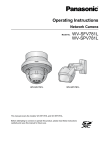
WV-SW559
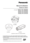
WV-SF539
WV-SP509
(Lens is optional for WV-SP509.)
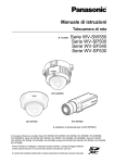
This manual covers the models: WV-SW550 Series (WV-SW559, WV-SW558, WV-SW559E, WV-SW558E),
WV-SP500 Series (WV-SP509, WV-SP508, WV-SP509E, WV-SP508E), WV-SF540 Series (WV-SF549,
WV-SF548, WV-SF549E, WV-SF548E), and WV-SF530 Series (WV-SF539, WV-SF538, WV-SF539E,
WV-SF538E).
Before attempting to connect or operate this product, please read these instructions
carefully and save this manual for future use.
The model number is abbreviated in some descriptions in this manual.
Preface
Preface
About the user manuals
There are 2 sets of operating instructions for the WV-SW559, WV-SW558, WV-SP509, WV-SP508,
WV-SF549, WV-SF548, WV-SF539, WV-SF538 (P model), WV-SW559E, WV-SW558E, WV-SP509E,
WV-SP508E, WV-SF549E, WV-SF548E, WV-SF539E, WV-SF538E (E model) as follows.
• Installation Guide: Explains how to install and connect devices.
When you use the WV-SW559/WV-SW559E or WV-SW558/WV-SW558E, refer to WV-SW559/
WV-SW558/WV-SW559E/WV-SW558E Installation Guide.
When you use the WV-SP509/WV-SP509E or WV-SP508/WV-SP508E, refer to WV-SP509/WV-SP508/
WV-SP509E/WV-SP508E Installation Guide.
When you use the WV-SF549/WV-SF549E, WV-SF548/WV-SF548E, WV-SF539/WV-SF539E, or
WV-SF538/WV-SF538E, refer to WV-SF549/WV-SF548/WV-SF539/WV-SF538/WV-SF549E/
WV-SF548E/WV-SF539E/WV-SF538E Installation Guide.
• Operating Instructions: Explains how to perform the settings and how to operate this camera. This
Operating Instructions covers the models: WV-SW559, WV-SW558, WV-SP509, WV-SP508, WV-SF549,
WV-SF548, WV-SF539, WV-SF538, WV-SW559E, WV-SW558E, WV-SP509E, WV-SP508E,
WV-SF549E, WV-SF548E, WV-SF539E, WV-SF538E.
The model number is abbreviated in some descriptions in this manual.
The screens used in these operating instructions show the case of WV-SW559 (P model). Depending on the
model used, the screens shown in the explanations may differ to the actual camera screens.
About notations
The following notations are used when describing the functions limited for specified models.
The functions without the notations are supported by all models.
SW559 : The functions with this notation are available when using the model WV-SW559.
SW558 : The functions with this notation are available when using the model WV-SW558.
SP509 : The functions with this notation are available when using the model WV-SP509.
SP508 : The functions with this notation are available when using the model WV-SP508.
SF549 : The functions with this notation are available when using the model WV-SF549.
SF548 : The functions with this notation are available when using the model WV-SF548.
SF539 : The functions with this notation are available when using the model WV-SF539.
SF538 : The functions with this notation are available when using the model WV-SF538.
Trademarks and registered trademarks
•
•
•
•
•
•
2
Microsoft, Windows, Windows Vista, Windows Media, Internet Explorer, ActiveX and DirectX are either
registered trademarks or trademarks of Microsoft Corporation in the United States and/or other countries.
Microsoft product screen shot(s) reprinted with permission from Microsoft Corporation.
iPad, iPhone, iPod touch, and QuickTime are trademarks of Apple Inc., registered in the U.S. and other
countries.
Android is a trademark of Google Inc. Use of this trademark is subject to Google Permissions.
SDXC Logo is a trademark of SD-3C, LLC.
All other trademarks identified herein are the property of their respective owners.
Operating Instructions
Preface
Abbreviations
The following abbreviations are used in these operating instructions.
Microsoft® Windows® 7 is described as Windows 7.
Microsoft® Windows Vista® is described as Windows Vista.
Microsoft® Windows® XP SP3 is described as Windows XP.
Windows® Internet Explorer® 9.0, Windows® Internet Explorer® 8.0, Windows® Internet Explorer® 7.0 and
Microsoft® Internet Explorer® 6.0 are described as Internet Explorer.
SDXC/SDHC/SD memory card is described as SD card or SD memory card.
Universal Plug and Play is described as UPnP™.
Viewer software
It is necessary to install the viewer software “Network Camera View 4S” to display images on a PC. This
software can be installed directly from the camera or by selecting the [Install] button next to [Viewer
Software] on the menu of the CD-ROM provided, and then following the on-screen instructions.
IMPORTANT
•
•
•
•
The default setting of “Automatic installation of viewer software” is “On”. Follow the instructions on
page 197 when the message is displayed on the information bar of the browser.
When the “Live” page is displayed for the first time, the install wizard of the ActiveX® control required
to display images from the camera will be displayed. Follow the instructions of the wizard.
When the install wizard is displayed again even after completing the installation of the ActiveX, restart
the PC.
The viewer software used on each PC should be licensed individually. The number of installations of
the viewer software from the camera can be checked on the [Upgrade] tab of the “Maintenance” page
(®page 181). Refer to your dealer for the software licensing.
Operating Instructions
3
Table of Contents
Table of Contents
1 Monitor images on a PC ..........................................................................7
1.1
1.2
1.3
1.4
1.5
Monitor images from a single camera .............................................................................7
About the “Live” page ....................................................................................................10
Monitor cropping images ...............................................................................................13
Monitor picture in picture images .................................................................................15
Monitor images from multiple cameras ........................................................................16
2 Monitor images on a cellular phone/mobile terminal .........................17
2.1
2.2
Monitor images on a cellular phone ..............................................................................17
Monitor images on a mobile terminal ............................................................................19
3 Record images on the SD memory card manually (WV-SW559/
WV-SP509/WV-SF549/WV-SF539) .........................................................25
4 Action at an alarm occurrence ..............................................................27
4.1
4.2
Alarm type ........................................................................................................................27
Action at an alarm occurrence .......................................................................................27
5 Transmit images onto an FTP server ...................................................29
5.1
5.2
5.3
Transmit an alarm image at an alarm occurrence (Alarm image
transmission) ...................................................................................................................29
Transmit images at a designated interval or period (FTP periodic image
transmission) ...................................................................................................................29
Save images on the SD memory card when images fail to transmit using the FTP
periodic image transmission function (WV-SW559/WV-SP509/WV-SF549/
WV-SF539) .......................................................................................................................30
6 Display the log list (WV-SW559/WV-SP509/WV-SF549/
WV-SF539) ..............................................................................................31
7 Playback of images on the SD memory card (WV-SW559/WV-SP509/
WV-SF549/WV-SF539) ............................................................................35
7.1
7.2
About the playback page ................................................................................................36
Download the images (When “H.264(1)” or “H.264(2)” is selected for “Recording
format” of the SD memory card) ....................................................................................38
8 About the network security ...................................................................40
8.1
Equipped security functions ..........................................................................................40
9 Display the setup menu from a PC .......................................................41
9.1
9.2
9.3
How to display the setup menu .....................................................................................41
How to operate the setup menu .....................................................................................43
About the setup menu window ......................................................................................45
10 Configure the basic settings of the camera [Basic] ...........................47
10.1
10.2
10.3
10.4
4
Configure the basic settings [Basic] .............................................................................47
Configure the settings relating to the SD memory card [SD memory card] (WV-SW559/
WV-SP509/WV-SF549/WV-SF539) ..................................................................................51
Access copy images saved on the SD memory card onto the PC [SD memory card
images] (WV-SW559/WV-SP509/WV-SF549/WV-SF539) ..............................................59
Configure the settings relating to the logs [Log] (WV-SW559/WV-SP509/WV-SF549/
WV-SF539) .......................................................................................................................68
Operating Instructions
Table of Contents
10.4.1
10.4.2
10.4.3
How the logs and images are saved depending on the settings for “Alarm” ..................70
How the logs and images are saved depending on the settings for “Manual/
Schedule” .......................................................................................................................71
How the logs and images are saved depending on the settings for “FTP error” ............73
11 Configure the settings relating to images and audio [Image/
Audio] ......................................................................................................74
11.1
11.2
11.3
11.4
11.4.1
11.4.2
11.5
11.6
11.7
11.8
11.9
11.10
11.11
11.12
Configure the settings relating to the image capture mode [JPEG/H.264] ................74
Configure the settings relating to JPEG images [JPEG/H.264] ..................................75
Configure the settings relating to H.264 images [JPEG/H.264] ..................................77
Configure the settings relating to image adjust, focus, back focus, extra optical zoom,
privacy zone, VIQS, and lens distortion compensation [Image quality] ....................83
Configure the settings relating to image quality (“Image adjust” setup menu) ...............84
Set mask areas ..............................................................................................................90
Configure the focus setting (“Focus” setup menu) (WV-SW559/WV-SW558/WV-SF549/
WV-SF548/WV-SF539/WV-SF538) ..................................................................................94
Configure the back focus setting (“Back focus” setup menu) (WV-SP509/
WV-SP508) .......................................................................................................................95
Adjust the angular field of view using the extra optical zoom function ....................96
Configure the settings relating to the privacy zone (“Privacy zone” setup
menu) ...............................................................................................................................97
Configure the VIQS setting ............................................................................................99
Configure the VIQS area ...............................................................................................101
Configure the settings relating to lens distortion compensation ............................102
Configure the settings relating to audio [Audio] (WV-SW559/WV-SP509/WV-SF549/
WV-SF539) .....................................................................................................................103
12 Configure the multi-screen settings [Multi-screen] ..........................106
13 Configure the alarm settings [Alarm] .................................................108
13.1
13.2
13.3
13.4
13.5
13.6
13.6.1
13.7
13.8
Configure the settings relating to the alarm action [Alarm] .....................................108
Configure the settings relating to the alarm image [Alarm] ......................................109
Configure the settings relating to H.264 recording [Alarm] (WV-SW559/WV-SP509/
WV-SF549/WV-SF539) ...................................................................................................111
Configure the settings relating to the alarm output terminal [Alarm] ......................112
Change the AUX name [Alarm] ....................................................................................113
Configure the VMD settings [VMD area] .....................................................................114
Set the VMD areas [VMD area] ....................................................................................116
Configuration of the settings relating to the E-mail notification [Notification] .......118
Configure the settings relating to Panasonic alarm protocol [Notification] ...........119
14 Configure the setting relating to the image recognition [Advanced
func.] .....................................................................................................122
14.1
14.2
Configure the settings relating to the XML notification [XML notification] .............122
Configuration of the settings relating to the face detection [Face detection] ........123
15 Configure the settings related to advanced view [Advanced
view] ......................................................................................................125
15.1
15.2
Configure the settings relating to cropping [Cropping] ............................................125
Configure the picture in picture settings [PiP] ...........................................................126
16 Configure the settings relating to the authentication [User
mng.] .....................................................................................................131
16.1
Configure the settings relating to the user authentication [User auth.] ..................131
Operating Instructions
5
Table of Contents
16.2
16.3
Configure the settings relating to the host authentication [Host auth.] ..................132
Configure the settings relating to the priority stream [System] ...............................133
17 Configure the settings of the servers [Server] ..................................136
17.1
17.2
17.3
Configure the settings relating to the E-mail server [E-mail] ...................................136
Configure the settings relating to the FTP server [FTP] ...........................................137
Configure the settings relating to the NTP server [NTP] ...........................................138
18 Configuring the network settings [Network] .....................................141
18.1
18.2
18.2.1
18.2.2
18.2.3
18.2.4
18.2.5
18.3
18.3.1
18.4
18.4.1
18.4.2
18.4.3
18.4.4
18.4.5
18.4.6
18.5
18.6
18.7
18.7.1
18.7.2
Configure the network settings [Network] ..................................................................141
Configure the HTTPS settings .....................................................................................149
Generation of the CRT key (SSL encryption key) ........................................................150
Generation of the self-signed certificate (security certificate) .......................................151
Generation of CSR (Certificate Signing Request) ........................................................153
Installation of the server certificate ...............................................................................154
Configuration of the connection protocol ......................................................................155
Access the camera using the HTTPS protocol ..........................................................156
Install the security certificate ........................................................................................156
Configure the settings relating to DDNS [DDNS] .......................................................166
Configuration of the DDNS service (Example of the “Viewnetcam.com” service) ........167
When using the “Viewnetcam.com” service .................................................................168
Procedure to register information for the “Viewnetcam.com” service ...........................169
Checking the information registered for the “Viewnetcam.com” service ......................170
When using “Dynamic DNS Update” ............................................................................170
When using “Dynamic DNS Update(DHCP)” ...............................................................171
Configure the settings relating to SNMP [SNMP] ......................................................171
Configure the settings relating to the FTP periodic image transmission [FTP img.
trans.] .............................................................................................................................172
Configure the schedule settings of the FTP periodic image transmission [FTP img.
trans.] .............................................................................................................................174
How to set the schedules .............................................................................................174
How to delete the set schedule ....................................................................................175
19 Configure the settings relating to the schedules [Schedule] ..........177
20 Maintenance of the camera [Maintenance] ........................................180
20.1
20.2
20.3
20.4
Check the system log [System log] .............................................................................180
Upgrade the firmware [Upgrade] .................................................................................181
Check the status [Status] .............................................................................................182
Reset the settings/Reboot the camera [Default reset] ...............................................183
21 About the displayed system log .........................................................185
22 Troubleshooting ...................................................................................189
23 Directory structure of drive B (WV-SW559/WV-SP509/WV-SF549/
WV-SF539) ............................................................................................199
6
Operating Instructions
1 Monitor images on a PC
1 Monitor images on a PC
The following are descriptions of how to monitor images from the camera on a PC.
1.1 Monitor images from a single camera
1. Start up the web browser.
2. Enter the IP address designated using the Panasonic “IP Setting Software” in the address box of the
browser.
• Example when entering an IPv4 address: http://URL registered using IPv4 address
http://192.168.0.10/
• Example when entering an IPv6 address: http://[URL registered using IPv6 address]
http://[2001:db8::10]/
<Example of IPv4 access>
<Example of IPv6 access>
IMPORTANT
•
•
When the HTTP port number is changed from “80”, enter “http://IP address of the camera + : (colon)
+ port number” in the address box of the browser. (Example: http://192.168.0.11:8080)
When the PC is in a local network, configure the proxy server setting of the web browser (under
[Internet Options...] under [Tools] of the menu bar) to bypass the proxy server for the local address.
Note
•
Refer to page 156 for further information about the case in which “HTTPS” is selected for
“HTTPS” - “Connection” on the [Network] tab of the “Network” page (®page 141).
Operating Instructions
7
1 Monitor images on a PC
3. Press the [Enter] key on the keyboard.
→ The “Live” page will be displayed. Refer to page 10 for further information about the “Live” page.
When “On” is selected for “User auth.”, the authentication window will be displayed before displaying live
images for the user name and password entries. The default user name and password are as follows.
User name: admin
Password: 12345
IMPORTANT
•
•
To enhance the security, change the password for the user name “admin”. It is recommended to change
this password periodically.
When displaying multiple H.264 images on a PC, images may not be displayed depending on the
performance of the PC.
Note
•
•
•
8
The maximum number of concurrent access user is 14 including users who is receiving H.264 images
and users who are receiving JPEG images. Depending on the set values for “Bandwidth control(bit
rate)” and “Max bit rate (per client)”, the maximum concurrent access number may be 14 or less users.
When 14 users are concurrently accessing, the access limit message will be displayed for users who
subsequently attempt to access. When “Multicast” is selected for “Transmission type” of “H.264”, only
the first user who accessed to monitor H.264 images will be included in the maximum number. The
second and subsequent users who are monitoring H.264 images will not be included in the maximum
number.
When “On” is selected for “H.264 transmission” (®page 79), H.264 images will be displayed. When
“Off” is selected, a JPEG image will be displayed. It is possible to display a JPEG image even when
“On” is selected for “H.264 transmission”. In this case, the refresh interval of JPEG images will be
limited to 5 fps.
The refresh interval may become longer depending on a network environment, PC performance,
photographic subject, access traffic, etc.
<Refresh interval of JPEG images>
When “On” is selected for “H.264 transmission”
– When “2 mega pixel [16:9]” / “1.3 mega pixel [16:9]” / “1.3 mega pixel [4:3]” is selected for “Image
capture mode”: max. 5fps
– When “3 mega pixel [4:3]” is selected for “Image capture mode”: max. 5fps
When “Off” is selected for “H.264 transmission”
Operating Instructions
1 Monitor images on a PC
– When “2 mega pixel [16:9]” / “1.3 mega pixel [16:9]” / “1.3 mega pixel [4:3]” is selected for “Image
capture mode”: max. 30fps
– When “3 mega pixel [4:3]” is selected for “Image capture mode”: max. 15fps
Operating Instructions
9
1 Monitor images on a PC
1.2 About the “Live” page
O
PQ R
S
T
U
A
B
C
D
E
F
G
H
I
J
V
K
L
M
N
[select language] pull-down-menu
The camera’s display language can be selected. The default language can be set in the [Language] in the
[Basic] settings. (®page 47)
[Setup] button*1
Displays the setup menu. The button will turn green and the setup menu will be displayed.
[Live] button
Display the “Live” page. The button will turn green and the “Live” page will be displayed.
[Compression] buttons
• [H.264] button: The letters “H.264” on the button will turn green and an H.264 image will be displayed.
When “On” is selected for “H.264 transmission” of “H.264(1)”, “H.264(2)”, the [H.264] button will be
displayed. (®page 79)
• [JPEG] button: The letters “JPEG” on the button will turn green and JPEG image will be displayed.
[Stream] buttons
These buttons will be displayed only when an H.264 image is displayed.
• [1] button: The letter “1” will turn green and images in the main area will be displayed in accordance
with the setting of “H.264(1)”. (®page 79)
• [2] button: The letter “2” will turn green and images in the main area will be displayed in accordance
with the setting of “H.264(2)”. (®page 79)
[Image capture size] buttons
These buttons will be displayed only when a JPEG image is displayed.
• [VGA] button: The letters “VGA” will turn green and images in the main area will be displayed in VGA
size.
• [QVGA] button: The letters “QVGA” will turn green and images in the main area will be displayed in
QVGA size.
• [1280x960] button: The letters “1280x960” will turn green and images in the main area will be
displayed in 1280 x 960 (pixels).
10
Operating Instructions
1 Monitor images on a PC
•
•
•
•
•
[640x360] button: The letters “640x360” will turn green and images in the main area will be displayed
in 640 x 360 (pixels).
[320x180] button: The letters “320x180” will turn green and images in the main area will be displayed
in 320 x 180 (pixels).
[1280x720] button: The letters “1280x720” will turn green and images in the main area will be
displayed in 1280 x 720 (pixels).
[1920x1080] button: The letters “1920x1080” will turn green and images in the main area will be
displayed in 1920 x 1080 (pixels).
[2048x1536] button: The letters “2048x1536” will turn green and images in the main area will be
displayed in 2048 x 1536 (pixels).
Note
•
The buttons [VGA], [QVGA], and [1280x960] are displayed only when “1.3 mega pixel [4:3]” is
selected for “Image capture mode”.
• The button [2048x1536] is displayed only when “3 mega pixel [4:3]” is selected for “Image capture
mode”.
• The buttons [640x360] and [320x180] are displayed only when “2 mega pixel [16:9]” or “1.3 mega
pixel [16:9]” is selected for “Image capture mode”.
• The button [1280x720] is displayed only when “1.3 mega pixel [16:9]” is selected for “Image capture
mode”.
• The button [1920x1080] is displayed only when “2 mega pixel [16:9]” is selected for “Image capture
mode”.
• When “2048x1536”, “1920x1080”, “1280x960”, or “1280x720” is selected for the image capture
size, it may become smaller than the actual size depending on the window size of the web browser.
[Image quality] buttons
These buttons will be displayed only when a JPEG image is displayed.
• [1] button: Images in the main area will be displayed in accordance with the setting for “Quality1” of
“Image quality setting”. (®page 75)
• [2] button: Images in the main area will be displayed in accordance with the setting for “Quality2” of
“Image quality setting”. (®page 75)
[Zoom] buttons
Images will be zoomed in on with the electronic zoom by the viewer software “Network Camera View
4S”.
• [x1] button: The letter “x1” will turn green and images in the main area will be displayed at x1.
• [x2] button: The letter “x2” will turn green and images in the main area will be displayed at x2.
• [x4] button: The letter “x4” will turn green and images in the main area will be displayed at x4.
[Brightness] buttons*2
The brightness is adjustable from 0 to 255.
•
(darker) button: The displayed image will be darker.
•
button: The adjusted brightness will return to the default brightness (64).
•
(brighter) button: Image will be brighter.
[Cropping] display
Cropping setup display is only displayed when the images set in “Cropping” on the [JPEG/H.264] tab of
the setup menu are displayed in the main area.
Within the full angle image, the white outlines display what position the image was cropped from. During
sequence operations, the cropping positions used by the sequence function are displayed in multiple white
outlines (the display shown in the cropping display is not updated by changes to the position of the
sequence or images).
[AUX] buttons*2
These buttons will be displayed only when “Terminal 3” of “Alarm” is set to “AUX output” on the setup menu.
(®page 108)
Operating Instructions
11
1 Monitor images on a PC
•
[Open] button: The letters “Open” on the button will turn green and the status of AUX connector will
be open.
• [Close] button: The letters “Close” on the button will turn green and the status of the AUX connector
will be closed.
SP509
SF549
SF539
[Rec. on SD] button*2 SW559
This button will be displayed only when “Manual” is selected for “Save trigger” on the setup menu.
(®page 54)
Click this button to manually record images on the SD memory card. Refer to page 25 for descriptions
of how to manually record images on the SD memory card.
SP509
SF549
SF539
[Log] button*1 SW559
[List] button will become available only when “On” is selected for “Save logs” on the setup menu.
(®page 68)
When this button is clicked, the log list will be displayed and images saved on the SD memory card can
be played.
Refer to page 31 for further information about the log list and for how to play images on the SD memory
card.
[Multi-screen]
Images from multiple cameras can be displayed on a multi-screen by registering cameras on the setup
menu. (®page 16)
Camera title
The camera title entered for “Camera title” on the [Basic] tab will be displayed. (®page 47)
Alarm occurrence indication button*2
This button will be displayed and will blink when an alarm has occurred. When this button is clicked, the
alarm output terminal will be reset and this button will disappear. (®page 27)
Full screen button
Images will be displayed on a full screen. To return to the “Live” page, press the [Esc] key. The aspect ratio
of displayed images will be adjusted in accordance with the monitor.
Snap shot button
Click this button to take a picture (a still picture). The picture will be displayed on a newly opened window.
When right-clicking on the displayed image, the pop-up menu will be displayed. It is possible to save the
image on the PC by selecting “Save” from the displayed pop-up menu.
When “Print” is selected, printer output is enabled.
Note
•
•
For the case of using Windows 7 or Windows Vista, the following settings may be required.
Open Internet Explorer, click [Tools] ® [Internet Options] ® [Security] ® [Trusted Sites] ®
[Sites]. Register the camera address on [Website] of the displayed trusted widows.
When it takes longer than the specified period to obtain the snap shot picture due to the network
environment, the snap shot picture may not be displayed.
SP509
SF549
SF539
Mic input button*3 SW559
Turns on/off the audio reception (hear audio from the camera on a PC). This button will be displayed only
when “Mic input”, “Interactive(Full-duplex)” or “Interactive(Half-duplex)” is selected for “Audio transmission/
reception” on the setup menu. (®page 103)
When this button is clicked, the button will turn into the
button and audio from the camera will not be
heard.
.
Audio volume can be adjusted (Low/ Middle/ High) by moving the volume cursor
SP509
SF549
SF539
Audio output button*3 SW559
Turns on/off the audio transmission (play audio from the PC on the unit speaker). This button will be
displayed only when “Audio output”, “Interactive(Full-duplex)” or “Interactive(Half-duplex)” is selected for
“Audio transmission/reception” on the setup menu. (®page 103)
The button will blink during the audio transmission.
12
Operating Instructions
1 Monitor images on a PC
When this button is clicked, the button will turn into the
button and audio from the PC will not be heard.
Audio output volume can be adjusted (Low/Middle/High) by moving the volume cursor
.
Note
•
•
•
•
When a user is using the audio transmission function with “Interactive(Half-duplex)” selected, the
receiver button and the transmission button will be inoperable for the other users. When
“Interactive(Full-duplex)” is selected, the transmission button is inoperable for other users.
Possible duration of audio transmission is up to 5 minutes per transmission. When 5 minutes have
passed, the audio transmission will automatically stop. To turn the audio transmission function on,
click the [Audio output] button again.
When the camera is restarted, the adjusted volume level (for both the audio transmission and
reception) will return to the level that had been set on the [Audio] tab on the setup menu.
(®page 103)
Actual volume level will change in three steps even though the volume cursor can be adjusted
minutely.
SP509
SF549
SF539
SD recording status indicator SW559
The status of the SD recording can be checked with this indicator.
When the SD recording starts, the SD recording status indicator will light red. It will go off when the SD
recording stops.
This indicator will be displayed when “Manual” or “Schedule” is selected for “Save trigger” on the setup
menu. (®page 51)
Main area
Images from the camera will be displayed in this area.
The current time and date will be displayed according to the settings configured for “Time display format”
and “Date/time display format”. (®page 48)
Note
•
•
*1
*2
*3
When operated by a lower access level user, images displayed on the screen may be changed
temporarily. This does not affect operation of the camera.
Depending on the PC in use, screen tearing* may occur when the shooing scene drastically changes
due to the GDI restrictions of the OS.
*A phenomenon in which portions of the screen are displayed out of alignment.
Only operable by users whose access level is “1. Administrator”.
Only operable by users whose access level is “1. Administrator” or “2. Camera control” when “On” is selected for “User auth.”
(®page 131)
Operable by users who belong to the access level selected for “Permission level of audio trans./recep.” on the [Audio] tab of the
“Image/Audio” page. Refer to page 103 for the permission level of audio.
1.3 Monitor cropping images
Full angle images and cropping images can be transmitted at the same time.
The cropping function must be configured in order to transmit cropping images. (®page 125)
H.264(2) or JPEG (VGA/QVGA/640x360/320x180) images can be set as cropping images.
By matching the settings of the [Compression] and [Stream] buttons on the “Live” page to the “Cropping”
settings (“H.264”, “JPEG(VGA)/JPEG(640x360)”, or “JPEG(QVGA)/JPEG(320x180)”) configured on the
[JPEG/H.264] tab, cropping images will be displayed on the [Cropping] display of the “Live” page and the main
area.
Operating Instructions
13
1 Monitor images on a PC
Cropping
A
You can crop areas that you want to monitor.
By setting multiple cropping areas, up to 4 areas can be displayed in a sequence.
Sequence display using the cropping function
B
C
A
A
14
B
Operating Instructions
C
A
B
C
1 Monitor images on a PC
Note
•
The cropping function can be used only when “2 mega pixel [16:9]”, “1.3 mega pixel [16:9]”, or “1.3
mega pixel [4:3]” is selected for “Image capture mode”.
1.4 Monitor picture in picture images
By using the picture in picture function, a cropping image or an alarm image can be added to an image and
transmitted.
The picture in picture function must be configured before it can be used. (®page 126)
When the picture in picture function is used, combined JPEG and H.264 images with the following image
capture sizes are transmitted.
• When “2 mega pixel [16:9]” is selected for “Image capture mode”: 1920x1080
• When “1.3 mega pixel [16:9]” is selected for “Image capture mode”: 1280x720
• When “1.3 mega pixel [4:3]” is selected for “Image capture mode”: 1280x960
Note
•
The picture in picture function can only be used when “2 mega pixel [16:9]”, “1.3 mega pixel [16:9]”, or
“1.3 mega pixel [4:3]” is selected for “Image capture mode”.
The type of images to be combined can be selected from “Picture in picture mode” on the [PiP] tab
(®page 126).
When “Live” is selected in “Picture in picture mode”, a predetermined area is combined as a sub image and
transmitted.
When an alarm trigger is selected in “Picture in picture mode”, a predetermined area is transmitted as a sub
image according to each setting.
A
B
Main image
Sub image
Operating Instructions
15
1 Monitor images on a PC
1.5 Monitor images from multiple cameras
Images from multiple cameras can be displayed on a multi-screen. Images from 4 cameras (up to 16 cameras)
can be displayed simultaneously. To display images on a multi-screen, it is necessary to register cameras in
advance. 4 cameras can be registered as a group and up to 4 groups (16 cameras) can be registered.
(®page 106)
IMPORTANT
•
When displaying images on a 16-screen, panning, tilting and zooming operations become unavailable
for images from cameras with Pan/Tilt/Zoom functions.
When displaying images on a 4-screen, panning, tilting and zooming operations become available only
for images from cameras with Pan/Tilt/Zoom functions. Refer to the [Readme] file on the provided
CD-ROM for further information about the compatible cameras and their versions. Or refer to our
website (http://panasonic.net/pss/security/support/info.html).
Only JPEG images can be displayed on a multi-screen. Audio will not be heard.
When the power is turned off or the LAN cable is disconnected while displaying images, displaying
images on a multi-screen from the “Live” page will become unavailable.
When displaying the image on a multi-screen and “16:9” is selected for the aspect ratio, the image will
be displayed altered vertically to the aspect ratio of “4:3”.
“Network Camera Recorder with Viewer Software Lite” which supports live monitoring and recording
images from multiple cameras is available. For further information, refer to our website
(http://panasonic.net/pss/security/support/info.html).
•
•
•
•
•
1. Click the desired [Multi-screen] on the “Live” page.
→ Images from the registered cameras will be displayed on a selected multi-screen (screen can be split
up to 16 areas). The following are instructions when displaying on a 4-split screen.
A
B
C
To show 1 camera screen, click the [Live] button.
You can also click “1” below “Multi-screen” or “Back” to display the camera's “Live” page.
Click the [Multi-screen] button to display images from cameras in a multi-screen of 4 to 16 screens.
Click a camera title. Live images from the camera corresponding to the clicked camera title will be
displayed on the “Live” page of the newly opened window.
16
Operating Instructions
2 Monitor images on a cellular phone/mobile terminal
2 Monitor images on a cellular phone/mobile
terminal
2.1 Monitor images on a cellular phone
It is possible to connect to the camera using a cellular phone via the Internet and monitor images (JPEG only)
from the camera on the screen of the cellular phone.
IMPORTANT
•
•
•
When the authentication window is displayed, enter the user name and password. The default user
name and password are as follows.
User name: admin
Password: 12345
To enhance the security, change the password for the user “admin”. (®page 131)
If the cellular phone in use is not compatible with UTF-8 encode, it is impossible to display the screen
correctly.
When “3 mega pixel [4:3]” is selected for “Image capture mode”, images cannot be monitored on a
cellular phone. Select “2 mega pixel [16:9]”, “1.3 mega pixel [16:9]”, or “1.3 mega pixel [4:3]” for “Image
capture mode” to monitor images.
Note
•
It is necessary to configure the network settings of the cellular phone in advance to connect to the
Internet and monitor images from the camera. (®page 141)
Operating Instructions
17
2 Monitor images on a cellular phone/mobile terminal
1. Access to “http://IP address/mobile”*1 or “http://Host name registered in the DDNS server/mobile” using a
cellular phone.
→ Images from the camera will be displayed.
A
B
C
D
Functions
Outline of functions
A Refresh
Refreshes the camera images by pressing the dial key “5”.
B Resolution control
Changes the image capture size by pressing the dial key “0”.
•
Image in the aspect ratio of “4:3”
Changes the image capture size
between 320x240 (default) and
640x480.
•
Image in the aspect ratio of
“16:9”
Changes the image capture size
between 320x180 (default) and
640x360.
C Image quality
control
It is possible to change the image quality between “Quality1” and
“Quality2”. (®page 75)
D AUX control*2
Controls the AUX terminal.
These buttons will be displayed only when “AUX output” is selected for
“Terminal 3” on the setup menu. (®page 108)
Note
•
•
18
Some cellular phones cannot change the image capture size even when resolution is changed by
resolution control.
When the HTTP port number is changed from “80”, enter “http://IP address: (colon) + port number/
mobile”*1 in the address box of the browser. When using the DDNS function, access to “http://Host
name registered in the DDNS server: (colon) + port number/mobile”.
Operating Instructions
2 Monitor images on a cellular phone/mobile terminal
•
•
•
•
•
*1
*2
When “HTTPS” is selected for “HTTPS” - “Connection” on the [Network] tab of the “Network” page,
enter as follows.
“https://IP address: (colon) + port number/mobile” or “https://Host name registered in the DDNS server:
(colon) + port number/mobile”
When the authentication window is displayed, enter the user name of an administrator or user and
password. Depending on the cellular phone in use, password entry may be required each time the
screen is switched.
It is impossible to transmit/receive audio using a cellular phone.
Depending on the cellular phone in use, larger size images may not be displayed. In this case, selecting
“9 Low” for “Image quality setting” of “JPEG” (®page 75) may sometimes solve this problem.
Depending on the cellular phone in use or its contract plan, it may be impossible to access.
IP address is the global WAN IP address of the router that can be accessed via the Internet.
When “User auth.” is set to “On” (®page 131), only users with the access level of “1. Administrator” or “2. Camera control” will be
displayed.
2.2 Monitor images on a mobile terminal
It is possible to connect to the camera using a mobile terminal via the Internet and monitor images (MJPEG
only) from the camera on the screen of the mobile terminal. It is also possible to refresh images to display the
latest image.
The compatible mobile terminals are shown as follows. (As of April, 2012)
– iPad, iPhone, iPod touch (iOS 4.2.1 or later)
– Android™ mobile terminals
Only JPEG images can be viewed from standard Android mobile terminal browsers.
For further information about compatible devices, refer to our website
(http://panasonic.net/pss/security/support/info.html).
IMPORTANT
•
•
•
When the authentication window is displayed, enter the user name and password. The default user
name and password are as follows.
User name: admin
Password: 12345
To enhance the security, change the password for the user “admin”. (®page 131)
When “3 mega pixel [4:3]” is selected for “Image capture mode”, images cannot be monitored on a
mobile terminal. Select “2 mega pixel [16:9]”, “1.3 mega pixel [16:9]”, or “1.3 mega pixel [4:3]” for “Image
capture mode” to monitor images.
When “2 mega pixel [16:9]” is selected for “Image capture mode”, the maximum image capture size is
640x360.
Note
•
It is necessary to configure the network settings of the mobile terminal in advance to connect to the
Internet and monitor images from the camera. (®page 141)
Operating Instructions
19
2 Monitor images on a cellular phone/mobile terminal
1. Access to “http://IP address/cam”*1 or “http://Host name registered in the DDNS server/cam” using a mobile
terminal.
→ Images from the camera will be displayed.
A
B
C
Live images area
Displays images from the camera.
Operation buttons area
When functions are selected in the function selection area C, buttons to operate those functions are
displayed.
Function selection area
When functions that can be operated are selected, operation buttons are displayed in the operation
buttons area B.
20
Operating Instructions
2 Monitor images on a cellular phone/mobile terminal
2. Click the button of the function that you want to operate.
A
B
Resolution control
AUX control
Each function is explained below.
Resolution control
button to display the buttons used to select the resolution on the screen. The resolution
Press the
can be changed by selecting a resolution setting from the buttons.
Image capture mode
• “2 mega pixel [16:9]” images: Changes the image capture size between 320x180 and 640x360
(default).
• “1.3 mega pixel [16:9]” images: Changes the image capture size between 320x180, 640x360
(default), and 1280x720.
• “1.3 mega pixel [4:3]” images: Changes the image capture size between 320x240, 640x480
(default), and 1280x960.
Operating Instructions
21
2 Monitor images on a cellular phone/mobile terminal
AUX control
button to display the buttons used to operate the AUX output on the screen. The AUX
Press the
output terminals can be controlled with the
and
buttons.
This function is only displayed when [Terminal 3] is set to [AUX output] on the settings menu.
(®page 108)
22
Operating Instructions
2 Monitor images on a cellular phone/mobile terminal
Note
•
•
•
•
•
•
•
You can change the image size displayed on the mobile terminal by accessing the following addresses.
– Large display: http://IP address/cam/dl
– Medium display: http://IP address/cam/dm
– Small display: http://IP address/cam/ds
When the resolution is changed by the resolution control, the displayed resolution changes but the
image size remains the same.
When the HTTP port number is changed from “80”, enter “http://IP address: (colon) + port number/
cam”*1 in the address box of the browser. When using the DDNS function, access to “http://Host name
registered in the DDNS server: (colon) + port number/cam”*2.
When “HTTPS” is selected for “HTTPS” - “Connection” on the [Network] tab of the “Network” page,
enter as follows.
“https://IP address: (colon) + port number/cam” or “https://Host name registered in the DDNS server:
(colon) + port number/cam”
When the authentication window is displayed, enter the user name of an administrator or user and
password. Depending on the mobile terminal in use, password entry may be required each time the
screen is switched.
It is impossible to transmit/receive audio using a mobile terminal.
Depending on the mobile terminal in use, larger size images may not be displayed. In this case,
selecting “9 Low” for “Image quality setting” of “JPEG” (®page 75) may sometimes solve this
problem.
Operating Instructions
23
2 Monitor images on a cellular phone/mobile terminal
•
*1
*2
24
Depending on the mobile terminal in use or its contract plan, it may be impossible to access.
IP address is the global WAN IP address of the router that can be accessed via the Internet. However, when accessing the same
LAN as the camera with a wireless compatible mobile terminal, the IP address is the local IP address.
Only when accessing the camera via the Internet.
Operating Instructions
3 Record images on the SD memory card manually (WV-SW559/WV-SP509/WV-SF549/WV-SF539)
3 Record images on the SD memory card
manually (WV-SW559/WV-SP509/WV-SF549/
WV-SF539)
Images displayed on the “Live” page can be recorded on the SD memory card manually. This button is operable
only when “Manual” is selected for “Save trigger” on the [SD memory card] tab on the “Basic” page of the setup
menu. (®page 54)
It is possible to select “JPEG”, “H.264(1)”, or “H.264(2)” on “Recording format” of the setup menu.
(®page 52) When “JPEG” is selected for “Recording format”, still image data are recorded. When “H.
264(1)” or “H.264(2)” is selected, video data are recorded.
Images recorded on the SD memory card can be copied onto the PC. (®page 59)
1. Display the “Live” page. (®page 7)
2. Click the [SD] button.
→ The SD recording window will open.
3. Click the [Start] button to start recording images on the SD memory card. The SD recording status indicator
will light red (®page 10) while images are being recorded on the SD memory card.
The image saving interval can be configured on the [SD memory card] tab of the “Basic” page.
(®page 51)
4. Click the [Stop] button to stop saving images on the SD memory card.
5. Click the [Close] button to close the window.
Operating Instructions
25
3 Record images on the SD memory card manually (WV-SW559/WV-SP509/WV-SF549/WV-SF539)
Note
•
•
•
26
Image data saved on Drive B can be obtained by executing “Access img.” on the [SD memory card]
tab and logging in from the user authentication window (®page 59).
The destination to save image data is a fixed directory on Drive B. Refer to “Directory structure of drive
B” (®page 199).
When the [Start] button is clicked immediately after the [Stop] button is clicked, saving of images may
not start. In this case, click the [Start] button again.
“Network Camera Recorder with Viewer Software Lite” which supports live monitoring and recording
images from multiple cameras is available. For further information, refer to our website
(http://panasonic.net/pss/security/support/info.html).
Operating Instructions
4 Action at an alarm occurrence
4 Action at an alarm occurrence
The alarm action (camera action at an alarm occurrence) will be performed when the following alarms occur.
4.1 Alarm type
•
•
•
Terminal alarm: When connecting an alarm device such as a sensor to the alarm input terminal of the
camera, the alarm action will be performed when the connected alarm device is activated.
VMD alarm: When motion is detected in the set VMD area, the alarm action will be performed.
*VMD stands for “Video Motion Detection”.
Command alarm: When a Panasonic alarm protocol is received from the connected device via a network,
the alarm action will be performed.
4.2 Action at an alarm occurrence
Display the alarm occurrence indication button on the “Live” page
The alarm occurrence indication button will be displayed on the “Live” page at an alarm occurrence.
(®page 10)
IMPORTANT
•
When “Polling(30s)” is selected for “Alarm status update mode” (®page 47), the Alarm occurrence
indication button will be refreshed in 30-second intervals. For this reason, it may take a maximum of
30 seconds until the alarm occurrence indication button is displayed on the “Live” page at an alarm
occurrence.
Notify of alarm occurrences to the device connected to the alarm connector
It is possible to output signals from the alarm output terminal of the camera and sound the buzzer when an
alarm occurs. The settings for the alarm output can be configured in the “Alarm output terminal setup” section
of the [Alarm] tab of the “Alarm” page. (®page 112)
Save images on the SD memory card
SW559
SP509
SF549
SF539
When an alarm occurs, images (JPEG/H.264) will be saved on the SD memory card. The settings to save
images on the SD memory card can be configured on the [SD memory card] tab (®page 51) of the “Basic”
page and the [Alarm] tab of the “Alarm” page. (®page 109)
Transmit an image onto a server automatically
An alarm image can be transmitted at an alarm occurrence to the server designated in advance. The settings
required to transmit an alarm image to a server can be configured in the “Alarm image” section on the
[Alarm] tab of the “Alarm” page (®page 109) and the [FTP] tab of the “Server” page (®page 137).
IMPORTANT
•
Select “FTP error” for “Save trigger” on the [SD memory card] tab when using the SD memory card.
When “Alarm input” or “Manual” is selected for “Save trigger”, an alarm image will not be transmitted
at an alarm occurrence to the FTP server.
Operating Instructions
27
4 Action at an alarm occurrence
Notify of alarm occurrences by E-mail
Alarm E-mail (alarm occurrence notification) can be sent at an alarm occurrence to the E-mail addresses
registered in advance. Up to 4 addresses can be registered as recipients of the alarm E-mail. An alarm image
(still picture) can be sent with the alarm E-mail as an attached file. The settings for alarm E-mail can be
configured in the “E-mail notification” section on the [Notification] tab of the [Alarm] page (®page 118) and
the [E-mail] tab of the “Server” page (®page 136).
Notify of alarm occurrences to the designated IP addresses (Panasonic
alarm protocol notification)
This function is available only when a Panasonic device, such as the network disk recorder, is connected to
the system. When “On” is selected for “Panasonic alarm protocol notification”, the connected Panasonic device
will be notified that the camera is in the alarm state. The settings for Panasonic alarm protocol can be configured
in the Panasonic alarm protocol section of the [Notification] tab of the [Alarm] page. (®page 119)
28
Operating Instructions
5 Transmit images onto an FTP server
5 Transmit images onto an FTP server
Images can be transmitted to an FTP server. By configuring the following settings, transmission of images
captured at an alarm occurrence or captured at a designated interval to an FTP server will become available.
IMPORTANT
•
•
When using this function, set the user name and the password to access the FTP server to restrict
users who can log into the FTP server.
To transmit images to the FTP server, select “Not use” for “SD memory card”, or set “Save trigger” to
“FTP error” on the [SD memory card] tab of the “Basic” page when “JPEG” is selected for [Recording
format]. (®page 52)
5.1 Transmit an alarm image at an alarm occurrence
(Alarm image transmission)
An alarm image can be transmitted at an alarm occurrence to the FTP server. To transmit alarm images to an
FTP server, it is necessary to configure the settings in advance.
The settings for the FTP server can be configured on the [FTP] tab of the “Server” page. (®page 137)
The alarm image transmission function can be turned on/off in the “Alarm image” section of the [Alarm] tab of
the “Alarm” page. (®page 109)
Note
•
•
Depending on the network traffic, the number of the transmitted images may not reach the set number
of images to be transmitted.
Alarm images failed to be transmitted to the FTP server at an alarm occurrence will not be saved on
the SD memory card. However, images that fail to be transmitted with the FTP periodic image
transmission will be saved.
5.2 Transmit images at a designated interval or
period (FTP periodic image transmission)
Images can be transmitted at a designated interval or period. To transmit images at a designated interval or
period, it is necessary to configure the settings in advance.
The settings for the FTP server can be configured on the [FTP] tab of the “Server” page. (®page 137)
It is possible to determine whether or not to use the FTP periodic image transmission function and to configure
the settings relating to alarm images and the schedule on the “FTP img. trans.” tab of the “Network” page.
(®page 172)
Note
•
•
Depending on the line speed or the traffic, images may not be transmitted at the designated interval.
When “On” is selected for both the alarm image transmission function and the FTP periodic image
transmission function, the alarm image transmission function will be given priority over the FTP periodic
image transmission function. Therefore, images may not be transmitted at the interval designated on
the “FTP periodic image transmission” setting.
Operating Instructions
29
5 Transmit images onto an FTP server
5.3 Save images on the SD memory card when
images fail to transmit using the FTP periodic image
transmission function (WV-SW559/WV-SP509/
WV-SF549/WV-SF539)
Images that have failed to transmit using the FTP periodic image transmission can be saved automatically on
the SD memory card. It is possible to select a trigger to save images on the SD memory card on the [SD
memory card] tab of the “Basic” page. (®page 51)
To use the SD memory recording function featured in Panasonic network disk recorder, select “Off” for “FTP
periodic image transmission” (®page 173) and “FTP error” for “Save trigger” (®page 54).
IMPORTANT
•
We make no guarantee for any damages of files on the SD memory card incurred by malfunction or
error occurrence in files saved in the SD memory card regardless of what the cause may be.
Note
•
30
To refer to images of “FTP error”, “Save logs” needs to be set to “On” (®page 68).
Operating Instructions
6 Display the log list (WV-SW559/WV-SP509/WV-SF549/WV-SF539)
6 Display the log list (WV-SW559/WV-SP509/
WV-SF549/WV-SF539)
The setting items of the cameras will be displayed in list form.
• Alarm log: Logs of the alarm occurrences such as time and date of the alarm occurrences and the alarm
type will be displayed.
• Manual/Schedule log: Logs filed when images have been recorded manually or during the period of the
schedule on the SD memory card will be displayed.
• FTP trans. error log: Logs filed when the FTP periodic image transmission function has failed will be
displayed.
Each log list can be displayed only when “On” is selected for “Save logs” on the [Log] tab of the “Basic” page
(®page 68) respectively.
1. Display the “Live” page. (®page 7)
Operating Instructions
31
6 Display the log list (WV-SW559/WV-SP509/WV-SF549/WV-SF539)
2. Click the [List] button.
→ The log list will be displayed in a newly opened window (log list window).
A
Number of the listed logs
IMPORTANT
•
Only a single user can operate the log list window. Other users cannot access the log list window.
Note
•
•
When “Not use” is selected for “SD memory card”, the “Manual/Schedule log” list and the “FTP
trans. error log” list will not be displayed.
When “H.264(1)” or “H.264(2)” is selected for “Recording format” of the SD memory card, the “FTP
trans. error log” list will not be displayed.
3. Click the desired log type listed below “Log” to display the log list.
® The log list of the selected log type will be displayed.
32
Operating Instructions
6 Display the log list (WV-SW559/WV-SP509/WV-SF549/WV-SF539)
Note
•
When any images are saved on the SD memory card, the image can be displayed by clicking Time
and Date when “JPEG” is selected for “Recording format” of the setup menu. (®page 51)
About the log list window
Number of the listed logs
Total number of the logs of the selected log type and a number of the log being displayed on the top of the log
list will be displayed.
Note
•
Enter the desired log number and press the [Enter] key on the keyboard. The log of the designated
number will be displayed on the top of the log list.
[Top] button
Click this button to display the log listed at the top.
[Prev. page] button
Click this button to display the previous page of the log list.
Note
•
When the mouse button is held down while placing the mouse pointer on the [Prev. page] button, the
displayed log number will be decreased. When the mouse button is released, the decrement of the log
number will stop and the log number displayed at the moment when the mouse button is released will
be the top of the currently displayed page.
[Next page] button
Click this button to display the next page of the log list.
Note
•
When the mouse button is held down while placing the mouse pointer on the [Next page] button, the
displayed log number will be increased. When the mouse button is released, the increment of the log
number will stop and the log number displayed at the moment when the mouse button is released will
be the top of the currently displayed page.
[Last] button
Click this button to display the log listed at the bottom.
[Time & date]
Time and date when each log has been filed will be displayed.
Note
•
•
When “Off” is selected for “Time display format” (®page 47), time and date of alarm occurrence will
be displayed in 24-hour format.
The recording timing of logs is as follows.
• Alarm log: Alarm occurrence time and date will be filed as a log.
• Manual/Schedule log: Time and date when recording of images onto the SD memory card started
manually or during the period of the schedule will be filed as a log. When images are recorded
sequentially, logs will be filed every one hour. However, depending on the photographic subject
and the setting used, logs may be filed in periods of over on hour.
• FTP trans. error log: Logs will be filed every one hour.
Operating Instructions
33
6 Display the log list (WV-SW559/WV-SP509/WV-SF549/WV-SF539)
[Event]
The event type will be displayed. The event types will be displayed only when displaying the alarm log list.
• TRM1: Alarm by alarm input to Terminal 1
• TRM2: Alarm by alarm input to Terminal 2
• TRM3: Alarm by alarm input to Terminal 3
• VMD: Alarm by VMD alarm
• COM: Alarm by command alarm
[SD memory card]
Available capacity and the original capacity of the SD memory card will be displayed.
The displayed descriptions are the same descriptions displayed as “Remaining capacity” on the [SD memory
card] tab. (®page 57)
[Delete] button
Click this button to delete the currently displayed log list.
When using the SD memory card, images associated with the log list will also be deleted.
IMPORTANT
•
•
•
When many images are saved on an SD memory card, complete deletion may take several hours. (For
example, to delete 1 GB of JPEG images, approx. 1 hour may be needed.) In such a case, format the
SD memory card. Be aware that formatting the SD memory card causes all the images to be deleted.
(®page 57)
In the process of the deletion, only logs will be saved, and it is impossible to save images newly.
Do not turn off the power of the camera until the deletion is complete. When the power of the camera
is turned off in the process of the deletion, some images may remain on the SD memory card. In this
case, click the [Delete] button on the same log list window used to delete the logs.
[Download] button
Click this button to download all logs of the selected log list as a file onto the PC.
[Close] button
Click this button to close the log list window.
34
Operating Instructions
7 Playback of images on the SD memory card (WV-SW559/WV-SP509/WV-SF549/WV-SF539)
7 Playback of images on the SD memory card
(WV-SW559/WV-SP509/WV-SF549/WV-SF539)
When clicking a time and date listed on the log list window, the “Live” page will turn to the “Playback” page.
When images associated with the clicked time and date are on the SD memory card, the first image of them
will be displayed.
IMPORTANT
•
•
•
•
•
This function is available only when “JPEG” is selected for “Recording format” of the SD memory card.
When “H.264(1)” or “H.264(2)” is selected, the “Playback” page will not be displayed. However, images
can be downloaded. Refer to page 38 for descriptions of how to operate.
Refresh interval of images may become slow during playback or download.
When many images are saved on the SD memory card, it may take time to display images on the
“Playback” page.
Even when the size of the images saved on the SD memory card is “QVGA”, “1280x960”, or
“2048x1536”, the images will be displayed in VGA size on the “Playback” page. When “16:9” is selected
for the aspect ratio, images will be displayed in an image capture size of “640x360”, even “320x180”,
“1280x720”, or “1920x1080” is selected. Therefore, images may look coarse on the “Playback” page.
When playing images by selecting an FTP error log on the log list, images may not be played in order
of images recorded on the SD memory card if they have been recorded on the SD memory card with
selected value for the “Transmission interval” setting on the [FTP img. trans.] tab is “1min” or less.
A
Number of images
Operating Instructions
35
7 Playback of images on the SD memory card (WV-SW559/WV-SP509/WV-SF549/WV-SF539)
7.1 About the playback page
Number of images
When clicking a time and date listed on the log list window, total number of images associated with the clicked
time and date, and the number of the currently displayed image will be displayed.
Note
•
Enter the desired number of image and press the [Enter] key on the keyboard. The image of the
designated number will be displayed.
[REW] button
Each time the button is clicked, the playback speed will change.
When the [PLAY] button or the [REV PLAY] button is clicked during fast reverse playback, playback speed will
return to the normal playback speed.
[REV PLAY] button
Images will be played in reverse sequential order.
[PLAY] button
When this button is clicked, images will be played in sequential order.
[FF] button
Each time the button is clicked, the playback speed will change.
When the [PLAY] button or the [REV PLAY] button is clicked during fast playback/fast reverse playback,
playback speed will return to the normal playback speed.
[TOP] button
The first image will be displayed.
[PREV. IMAGE] button
The previous frame will be displayed and paused when this button is clicked during playback.
Each time this button is clicked during pausing, the frame previous to the currently displayed frame will be
displayed.
Note
•
When the mouse button is held down while the mouse pointer is on this button, the image number will
be decreased.
When the mouse button is released, the decreasing of the image number will stop and the image
corresponding to the currently displayed number will be displayed.
[PAUSE] button
Playback will be paused when this button is clicked during playback.
Playback will resume when this button is clicked during pausing.
[STOP] button
Playback will stop and the “Playback” window will turn to the “Live” page.
[NEXT IMAGE] button
The next frame will be displayed and paused when this button is clicked during playback.
Each time this button is clicked during pausing, the frame next to the currently displayed frame will be displayed.
Note
•
36
When the mouse button is held down while the mouse pointer is on this button, the image number will
be increased.
Operating Instructions
7 Playback of images on the SD memory card (WV-SW559/WV-SP509/WV-SF549/WV-SF539)
When the mouse button is released, the increment of the image number will stop and the image number
displayed at the moment when the mouse button is released will be displayed.
[LAST] button
The last image will be displayed.
Browse
[Start] button
The selected image will be downloaded onto the PC. Before downloading images, designate the destination
directory in advance. (®page 68)
The following window will be displayed when the [Start] button is clicked.
Select the image to be downloaded, and then click the [OK] button.
•
•
•
All: All images saved at the selected time and date will be downloaded.
Current image: Only the currently displayed image will be downloaded.
Download range: Images in the designated range of number of images will be downloaded.
Note
•
When the [Cancel] button is clicked in the process of the download, the download will be canceled. In
this case, images already downloaded before clicking the [Cancel] button will be saved on the PC.
[Browse] button
When successfully logged in after the user authentication process, a folder on the SD memory card in which
images are saved will be displayed. (®page 59)
Operating Instructions
37
7 Playback of images on the SD memory card (WV-SW559/WV-SP509/WV-SF549/WV-SF539)
7.2 Download the images (When “H.264(1)” or “H.
264(2)” is selected for “Recording format” of the SD
memory card)
IMPORTANT
• Depending on the network environment, download of video data may fail.
To play back video data recorded on the SD memory card, download the desired data, and save the data on
the PC. It is impossible to play back video data on the “Playback” page. For this reason, follow the procedure
below.
1. Click the time & date on the log list window. (®page 31)
→ The message window will be displayed to ask if it is OK to start download.
38
Operating Instructions
7 Playback of images on the SD memory card (WV-SW559/WV-SP509/WV-SF549/WV-SF539)
2. Select the image to be downloaded, and then click the [OK] button.
→ Image saved at the clicked time and date will be downloaded.
Note
•
•
•
*1
When the [Cancel] button is clicked in the process of the download, the download will be canceled. In
this case, video data already downloaded before clicking the [Cancel] button will be saved on the PC.
Downloading of the associated video data will be started. Before downloading images, designate the
destination directory in advance. (®page 68)
• When the [Cancel] button is clicked after the download is started, it may take time to cancel the
download.
• Video data are saved in the files of approx. 2 MB. When the file size of video data is more than
2 MB, two or more files will be downloaded.
It is possible to play back video data saved on the PC using such applications as QuickTime Player or
Windows Media® Player*1. However, we are not liable for performance relating to these applications.
Depending on the status of the SD memory card, QuickTime Player, or Windows Media Player, video
data cannot be played back.
The supported operating system is Windows 7 only.
Operating Instructions
39
8 About the network security
8 About the network security
8.1 Equipped security functions
The following security functions are featured in this camera.
Access restrictions by the host authentication and the user authentication
It is possible to restrict users from accessing the camera by setting the host authentication and/or the user
authentication to “On”. (®page 131, page 132)
Access restrictions by changing the HTTP port
It is possible to prevent illegal access such as port scanning, etc. by changing the HTTP port number.
(®page 144)
Access encryption by the HTTPS function
It is possible to enhance the network security by encrypting the access to cameras using the HTTPS
function. (®page 149)
IMPORTANT
•
•
•
Design and enhance security countermeasures to prevent leakage of information such as image data,
authentication information (user name and password), alarm E-mail information, FTP server
information, DDNS server information, etc. Perform the countermeasure such as access restriction
(using the user authentication) or access encryption (using the HTTPS function).
After the camera is accessed by the administrator, make sure to close the browser for added security.
Change the administrator password periodically for added security.
Note
•
40
When user authentication (authentication error) has failed to pass 8 times within 30 seconds using the
same IP address (PC), access to the camera will be denied for a while.
Operating Instructions
9 Display the setup menu from a PC
9 Display the setup menu from a PC
The settings of the camera can be configured on the setup menu.
IMPORTANT
•
The setup menu is only operable by users whose access level is “1. Administrator”. Refer to
page 131 for how to configure the access level.
9.1 How to display the setup menu
1. Display the “Live” page. (®page 7)
2. Click the [Setup] button on the “Live” page.
→ The window with the user name and password entry fields will be displayed.
3. Click the [OK] button after entering the user name and the password.
The default user name and password are as follows.
User name: admin
Password: 12345
Operating Instructions
41
9 Display the setup menu from a PC
→ The setup menu will be displayed. Refer to page 45 for further information about this menu.
42
Operating Instructions
9 Display the setup menu from a PC
9.2 How to operate the setup menu
A
B
Menu buttons
Setup page
1. Click the desired button in the frame on the left of the window to display the respective setup menu.
When there are tabs at the top of the “Setup” page displayed in the frame on the right of the window, click
the desired tab to display and configure the setting items relating to the name of the tab.
2. Complete each setting item displayed in the frame on the right of the window.
3. After completing each setting item, click the [Set] button to apply them.
IMPORTANT
•
When there are two or more [Set] and [Execute] buttons on the page, click the respective button to the
edited setting item.
<Example>
A
B
C
D
Operating Instructions
43
9 Display the setup menu from a PC
When completing the setting items in field A, click the [Set] button (B) below field (A).
The edited settings in field A will not be applied unless the [Set] button (B) below field (A) is clicked.
In the same manner as above, click the [Set] button (D) below field C when completing the setting
items in field C.
44
Operating Instructions
9 Display the setup menu from a PC
9.3 About the setup menu window
A
N
B
C
D
E
F
G
O
H
I
J
K
L
M
[Setup] button
Display the “Setup” page.
[Live] button
Display the “Live” page.
[Basic] button
Displays the “Basic” page. The basic settings such as time and date and camera title, and the settings
SP509
SF549
SF539 ) can be configured on the “Basic”
relating to the SD memory card ( SW559
page. (®page 47)
SP509
SF549
SF539
[Image/Audio] button SW559
Displays the “Image/Audio” page. The settings relating to image quality, image capture size, etc. of JPEG/
H.264 camera images can be configured on the “Image/Audio” page. (®page 74)
SP508
SF548
SF538
[Image] button SW558
Displays the “Image” page. The settings relating to image quality, image capture size, etc. of JPEG/H.264
camera images can be configured on the “Image” page. (®page 74)
[Multi-screen] button
Displays the “Multi-screen” page. The cameras from which images are to be displayed on a multi-screen
can be registered on the “Multi-screen” page. (®page 106)
[Alarm] button
Displays the “Alarm” page. The settings relating to alarm occurrences such as settings for the alarm action
at an alarm occurrence, the alarm occurrence notification, and the VMD area settings can be configured
on the “Alarm” page. (®page 108)
[Advanced func.] button
Displays the “Advanced func.” page. The setting relating to the XML notification, destinations of information
about the face detection and the settings relating to the face detection can be configured on the “Advanced
func.” page. (®page 122)
Operating Instructions
45
9 Display the setup menu from a PC
[Advanced view] button
Displays the “Advanced view” page. The settings relating to cropping and picture in picture (PiP) can be
configured on the “Advanced view”. (®page 125)
[User mng.] button
Displays the “User mng.” page. The settings relating to the authentication such as users and PCs
restrictions for accessing the camera can be configured on the “User mng.” page. (®page 131)
[Server] button
Displays the “Server” page. The settings relating to the E-mail server, the FTP server and the NTP server
to which the camera accesses can be configured on the “Server” page. (®page 136)
[Network] button
Displays the “Network” page. The network settings and the settings relating to DDNS (Dynamic DNS),
SNMP (Simple Network Management Protocol) and the FTP (File Transfer Protocol) periodic transmission
can be configured on the “Network” page. (®page 141)
[Schedule] button
Displays the “Schedule” page. On the “Schedule” page, it is possible to designate time zones to allow to
receive alarm input or to allow to activate the VMD detection function. (®page 177)
[Maintenance] button
Displays the “Maintenance” page. System log check, firmware upgrade, status check and initialization of
the setup menu can be carried out on the “Maintenance” page. (®page 180)
Camera title
The title of the camera whose settings are currently being configured will be displayed.
Setup page
Pages of each setup menu will be displayed. There are tabs for some setup menus.
46
Operating Instructions
10 Configure the basic settings of the camera [Basic]
10 Configure the basic settings of the camera
[Basic]
The basic settings such as camera title, time and date, SD memory card and the logs can be configured on
SP509
the “Basic” page. The “Basic” page has 3 tabs; the [Basic] tab, the [SD memory card] tab SW559
SF549
SF539 , and the [Log] tab
SW559
SP509
SF549
SF539 .
10.1 Configure the basic settings [Basic]
Click the [Basic] tab on the “Basic” page. (®page 41, page 43)
The settings such as the camera title, time and date, etc. can be configured on this page.
[Camera title]
Enter the title of the camera. Click the [Set] button after entering the title of the camera. The entered title will
be displayed in the “Camera title” field.
• Available number of characters: 0 - 20 characters
• Unavailable characters: " &
• Default: Varies as follows depending on the model in use.
WV-SW559 SW559 /WV-SW558 SW558 /WV-SP509 SP509 /WV-SP508 SP508 /WV-SF549
SF549 /WV-SF548
SF548 /WV-SF539
SF539 /WV-SF538
SF538
[Date/time]
Enter the current time and date. When “12h” is selected for “Time display format”, “AM” or “PM” can be selected.
• Available range: 01/01/2010 00:00:00 - 31/12/2035 23:59:59
Operating Instructions
47
10 Configure the basic settings of the camera [Basic]
IMPORTANT
•
Use an NTP server when the more accurate time & date setting is required for the system operation.
(®page 138)
[Time display format]
Select the time display format from “24h”, “12h” and “Off”. Enter the current hour reflecting this setting when
entering the current time and date for “Date/time”. To hide time and date, select “Off”.
• Default: 24h
[Date/time display format]
Select a date/time display format. When “2011/04/01 13:10:00” is set for “Date/time” after selecting “24h” for
“Date/time display format”, time & date will be respectively displayed as follows.
• DD/MM/YYYY: 01/04/2011 13:10:00
• MM/DD/YYYY: 04/01/2011 13:10:00
• DD/Mmm/YYYY: 01/Apr/2011 13:10:00
• YYYY/MM/DD: 2011/04/01 13:10:00
• Mmm/DD/YYYY: Apr/01/2011 13:10:00
• Default:
– DD/MM/YYYY (E model)
– Mmm/DD/YYYY (P model)
[Summer time (daylight saving)]
Select “In”, “Out” or “Auto” to determine whether or not to apply daylight saving time. Configure this setting if
the summer time (daylight saving time) is applied in the location where the camera is in use.
• In: Applies summer time. An asterisk (*) will be displayed on the left side of the displayed time and date.
• Out: Does not apply summer time.
• Auto: Applies summer time in accordance with the settings for “Start time & date” and “End time & date”
(month, week, day of the week, time).
• Default: Out
[NTP/Time zone]
When “NTP >>” is clicked, the [NTP] tab of the “Server” page will be displayed. (®page 138)
[Start time & date] [End time & date]
When “Auto” is selected for “Summer time (daylight saving)”, select the time & date for the start time and the
date time (month, week, day of the week, time).
[Camera title on screen]
Select “On” or “Off” to determine whether or not to display the camera title on the screen. When “On” is selected,
the character string entered for “Camera title on screen (0-9, A-Z)” will be displayed at the position selected
for “OSD”.
• Default: Off
[Camera title on screen (0-9, A-Z)]
Enter a character string to be displayed on the image.
• Available number of characters: 0 - 20 characters
• Available characters: 0-9, A-Z and the following marks.
!"#$%&'()*+,-./:;=?
• Default: None (blank)
48
Operating Instructions
10 Configure the basic settings of the camera [Basic]
[OSD] - [Position]
Select the position where the time and date and a character string to be displayed on the image of the “Live”
page.
• Upper left: The above information will be displayed at the upper left corner of the main area on the
“Live” page.
• Lower left: The above information will be displayed at the lower left corner of the main area on the
“Live” page.
• Upper right: The above information will be displayed at the upper right corner of the main area on the
“Live” page.
• Lower right: The above information will be displayed at the lower right corner of the main area on the
“Live” page.
• Default: Upper left
[Brightness status display]
Select “On” or “Off” to determine whether or not to display the status of brightness on images displayed on the
“Live” page when adjusting brightness.
• Default: On
[Upside-down]
Select “On” or “Off” to determine whether or not to turn the image upside-down.
• Default: Off
[Indicator]
Determine whether or not to use the following indicators. Select “On” to use the following indicators to check
the operational status by lighting them. Select “Off” to turn off the indicators at all times.
– Link indicator
– Access indicator
SF549
SF539
– SD memory card error indicator/AF indicator SW559
SP509
– SD memory card error indicator/ABF indicator
SF548
SF538
– AF indicator SW558
– ABF indicator SP508
• Default: On
Note
•
•
•
•
Link indicator (orange): This indicator will light when communication with the connected device is
available.
Access indicator (green): This indicator will light when accessing a network.
SF549
SF539 : Lights when an error
SD memory card error indicator/AF indicator (red) SW559
occurred in the SD memory card. This LED will blink in the process of the auto focus function and
blinking will stop when the focus adjustment is complete.
SD memory card error indicator/ABF indicator (red) SP509 : Lights when an error occurred in the SD
memory card. This LED will blink in the process of the auto back focus function and blinking will stop
when the focus adjustment is complete.
[Alarm status update mode]
Select an interval of the camera status notification from the following.
When the status of the camera changes, the alarm occurrence indication button, the [AUX] button or the SD
SP509
SF549
SF539 ) will be displayed to notify of the camera status.
saving status indicator ( SW559
• Polling(30s): Updates the status each 30 seconds and provide notification of the camera status.
• Real time: Provide notification of the camera status when the status has changed.
• Default: Real time
Operating Instructions
49
10 Configure the basic settings of the camera [Basic]
Note
•
Depending on the network environment, notification may not be provided in real time.
[Alarm status reception port]
When selecting “Real time” for “Alarm status update mode”, designate a port number to which the status change
notification is to be sent.
• Available port number: 1 - 65535
• Default: 31004
The following port numbers are unavailable since they are already in use.
20, 21, 23, 25, 42, 53, 67, 68, 69, 80, 110, 123, 161, 162, 443, 995, 10669, 10670
[Automatic installation of viewer software]
Determine whether or not to install the viewer software from this camera.
• On: Installs the viewer software from the camera automatically.
• Off: The viewer software cannot be installed from the camera.
• Default: On
IMPORTANT
•
•
It is impossible to display images and to receive/transmit audio between the camera and the PC when
the viewer software “Network Camera View 4S” is not installed on the PC.
The number of the viewer software installations can be checked on the [Upgrade] tab of the
“Maintenance” page.
[Language]
Select the language to initially display when the camera is accessed from the following.
English/Japanese/Italian/French/German/Spanish/Chinese/Russian
• Default: English
The language displayed on the “Live” page can also be changed. (®page 10)
50
Operating Instructions
10 Configure the basic settings of the camera [Basic]
10.2 Configure the settings relating to the SD
memory card [SD memory card] (WV-SW559/
WV-SP509/WV-SF549/WV-SF539)
Click the [SD memory card] tab on the “Basic” page. (®page 41, page 43)
The settings relating to the SD memory card can be configured on this page.
Operating Instructions
51
10 Configure the basic settings of the camera [Basic]
SD memory card
[SD memory card]
Select “Use” or “Not use” to determine whether or not to use the SD memory card.
• Default: Use
52
Operating Instructions
10 Configure the basic settings of the camera [Basic]
IMPORTANT
•
•
•
•
•
•
•
•
•
Select “Not use” when operating without an SD memory card.
When the setting is changed between “Use” and “Not use” while another user is during operation, the
operation will be canceled.
Before removing the SD memory card from the camera, it is necessary to select “Not use” first.
After inserting the SD memory card, it is necessary to select “Use” to use the SD memory card.
When playing or downloading images saved on the SD memory card, it is necessary to select “On” for
“Save logs” on the [Log] tab (®page 68) in advance.
When the image refresh interval is short, notification/recording timing or interval may become incorrect.
Notification/recording may also not be performed correctly as configured when multiple users are
receiving images. In this case, set the refresh interval longer.
There are limited times to overwrite on an SD memory card. When having a high frequency of
overwriting, the lifetime of the SD memory card may become shorter.
A lifetime of an SD memory card should be influenced by the number of the image files stored and log
savings on the SD memory card. Selecting “H.264(1)” or “H.264(2)” for “Recording format” can reduce
the number of files to be stored on the SD memory card.
The data writing speed will go down after data are repeatedly written down on an SD memory card.
[Recording format]
Select “JPEG”/“H.264(1)”/“H.264(2)” for the video encoding format of image data to be recorded on the SD
memory card.
• JPEG: Records still image data.
• H.264(1): Records video data (H.264(1)) in the MP4 video encoding format. Audio will not be recorded.
• H.264(2): Records video data (H.264(2)) in the MP4 video encoding format. Audio will not be recorded.
• Default: JPEG
Note
•
•
•
•
•
•
•
When “H.264(1)” is selected, it will become impossible to transmit images with the settings of H.
264(1). When “H.264(2)” is selected, it will become impossible to transmit images with the settings of
H.264(2).
When “H.264(1)” is selected, the settings for “H.264(1)” on the [JPEG/H.264] tab of the “Image/
Audio” page will be changed to the settings for “H.264 recording”.
When “H.264(2)” is selected, the settings for “H.264(2)” on the [JPEG/H.264] tab of the “Image/
Audio” page will be changed to the settings for “H.264 recording”.
When “H.264(1)” is selected, the priority band may not be maintained if “H.264(1)” for “Priority
stream” - “Stream type” on the [System] tab of the “User mng.” page.
When “H.264(2)” is selected, the priority band may not be maintained if “H.264(2)” for “Priority
stream” - “Stream type” on the [System] tab of the “User mng.” page.
When using the SD memory recording function of a Panasonic network disk recorder, select “JPEG”
for “Recording format”.
When the setting of “Recording format” is changed between “JPEG” and “H.264(1)” or “H.264(2)”,
format the SD memory card. (®page 57)
Due to the difference in file formats, the indication of remaining capacity of the SD memory card differs
between the cases when “JPEG” is selected and when “H.264(1)” or “H.264(2)” is selected for
“Recording format”.
When “H.264(1)” or “H.264(2)” is selected for “Recording format”, the following settings in “H.264
recording”; Image capture size, Frame rate, Max bit rate, Image quality, and Refresh interval will be
read from the settings in “H.264(1)” or “H.264(2)”. When “2s”, “3s”, “4s” or “5s” is selected for “Refresh
interval” of “H.264(1)” or “H.264(2)”, “Refresh interval” for “H.264 recording” will be set to “1s” after
changing “Recording format” to “H.264(1)” or “H.264(2)”. When “8192kbps”, “10240kbps”,
“12288kbps”, or “14336kbps” is set for “Max bit rate” in “H.264(1)”, “Max bit rate” for “H.264
recording” will be set for “4096kbps” after changing the “Recording format” to “H.264(1)”.
Operating Instructions
53
10 Configure the basic settings of the camera [Basic]
•
•
•
•
When the selection for “Recording format” is changed to “H.264(1)” or “H.264(2)”, the setting of “Save
logs” (the [Log] tab on the “Basic” page ®page 68) is changed together.
When “H.264(1)” or “H.264(2)” is selected for “Recording format”, alarm images are saved in
accordance with the settings of “Pre alarm” and “Post alarm (recording) duration” on the [Alarm] tab of
the “Alarm” page.
When “H.264(1)” or “H.264(2)” is selected for “Recording format”, the name of the saved file will be
given automatically.
When “Image capture mode” is selected for “3 mega pixel [4:3]”, “H.264(2)” is unavailable.
Common
[Remaining capacity notification]
When the E-mail notification function or the Panasonic alarm protocol function is used to provide notification
of the remaining capacity of the SD memory card, select a level to be notified at from the following.
50%/ 20%/ 10%/ 5%/ 2%
• Default: 50%
Note
•
Notification will be provided each time the remaining capacity of the SD memory card reached the
values above.
For example, notification will be provided each time the remaining capacity reaches 50%, 20%, 10%,
5% and 2% when “50%” is selected. Notification may not always be made at the very moment when
the remaining capacity of the SD memory card has reached each value.
[Save trigger]
Select a trigger to save images on the SD memory card from the following.
• FTP error: Saves images when images have failed to transmit to the FTP server by the FTP periodic image
transmission function. Available only for JPEG images.
• Alarm input: Saves images at an alarm occurrence.
• Manual: Saves images manually.
• Schedule: Saves images in accordance with the settings for “Schedule” (®page 177). Available only for
H.264 images.
• Default: FTP error
Note
•
•
•
•
•
When “H.264(1)” or “H.264(2)” is selected for “Recording format”, “FTP error” is unavailable.
Select “FTP error” when images are to be transmitted to the FTP server at an alarm occurrence.
When “Manual” or “Schedule” is selected when “H.264(1)” or “H.264(2)” is selected for “Recording
format”, even if “Save logs” (®page 68) of “Alarm” is set to “On”, detected alarm logs are not recorded
in the log list.
When “JPEG” is selected for “Recording format”, “Schedule” is unavailable.
When “3 mega pixel [4:3]” is selected for “Image capture mode”, “FTP error” is unavailable.
[Overwrite]
Determine whether or not to overwrite when the remaining capacity of the SD memory card becomes
insufficient.
This setting is available only when “Manual” or “Schedule” is selected for “Save trigger”.
• On: Overwrites when the remaining capacity of the SD memory card becomes insufficient. (The oldest
image is the first to be overwritten.)
• Off: Stops saving images on the SD memory card when the SD memory card becomes full.
• Default: Off
54
Operating Instructions
10 Configure the basic settings of the camera [Basic]
Note
•
The overwrite setting will be as follows according to the “Save trigger” setting.
• FTP error: Will not be overwritten.
• Alarm input: Will be overwritten.
• Manual, Schedule: Can be determined by selecting “On” or “Off” for “Overwrite”.
JPEG recording
This setting is available only when “JPEG” is selected for “Recording format” of the SD memory card.
[File name]
Enter the file name used for the image to be saved on the SD memory card. The file name will be as follows.
• File name: [“Entered file name” + “Time and date (year/ month/ day/ hour/ minute/ second)”] + “Serial
number”
• Available number of characters: 1 - 8 characters
• Unavailable characters: " & * / : ; < > ? \ |
Note
•
•
When “H.264(1)” or “H.264(2)” is selected for “Recording format”, the name of the saved file will be
given automatically.
When “FTP error” is selected for “Save trigger”, the file name entered for “File name” on the [FTP img.
trans.] tab of the “Network” page will be used for the file name of the image saved on the SD memory
card.
[Image saving interval/Number of images to be saved - Image saving interval]
When “Alarm input” or “Manual” is selected for “Save trigger”, select an interval (frame rate) of saving images
on the SD memory card from the following.
0.1fps/ 0.2fps/ 0.33fps/ 0.5fps/ 1fps
• Default: 1fps
Note
•
When “1920x1080” is selected for the image capture size of the JPEG images to be saved, “1fps”
cannot be selected.
[Image saving interval/Number of images to be saved - Number of images to be saved]
Select a number of alarm images to be saved on the SD memory card from the following.
10pics/ 20pics/ 30pics/ 50pics/ 100pics/ 200pics/ 300pics/ 500pics/ 1000pics/ 2000pics/ 3000pics
• Default: 100pics
Note
•
•
When “H.264(1)” or “H.264(2)” is selected for “Recording format”, “Pre alarm” and “Post alarm” can be
set on “H.264 recording” of [Alarm] tab.
“Number of images to be saved” can be configured only when “Alarm input” is selected for “Save
trigger”.
[Image capture size]
When “Manual” is selected for “Save trigger” and “JPEG” is selected for “Recording format”, select the image
capture size of the images to be saved on the SD memory card from the following.
When “2 mega pixel [16:9]” is selected for “Image capture mode”
1920x1080/640x360/320x180
When “1.3 mega pixel [16:9]” is selected for “Image capture mode”
1280x720/640x360/320x180
When “1.3 mega pixel [4:3]” is selected for “Image capture mode”
Operating Instructions
55
10 Configure the basic settings of the camera [Basic]
1280x960/VGA/QVGA
When “3 mega pixel [4:3]” is selected for “Image capture mode”
2048x1536 fix
• Default: 640x360
Note
•
•
•
When “FTP error” is selected for “Save trigger”, images will be saved with the image capture size
selected on the [FTP img. trans.] tab of the “Network” page.
When “H.264(1)” or “H.264(2)” is selected for “Recording format”, select the image capture size for “H.
264 recording” - “Image capture size” on the [SD memory card] tab.
When “Alarm input” is selected for “Save trigger”, images will be saved with the image capture size
selected on the [Alarm] tab of the “Alarm” page.
H.264 recording
This setting is available only when “H.264(1)” or “H.264(2)” is selected for “Recording format” of the SD memory
card.
When the [Set] button is clicked after selecting “H.264(1)” or “H.264(2)” in “Recording format”, “H.264
recording” is displayed on the lower part of the screen.
[Image capture size]
Select the image capture size from the following.
When “2 mega pixel [16:9]” is selected for “Image capture mode”
– H.264(1): 1920x1080/640x360/320x180
– H.264(2): 640x360/320x180
When “1.3 mega pixel [16:9]” is selected for “Image capture mode”
– H.264(1): 1280x720/640x360/320x180
– H.264(2): 640x360/320x180
When “1.3 mega pixel [4:3]” is selected for “Image capture mode”
– H.264(1): 1280x960/VGA/QVGA
– H.264(2): VGA/QVGA
When “3 mega pixel [4:3]” is selected for “Image capture mode”
– H.264(1): 1280x960 fix
[Recording priority]
Select “Constant bit rate” or “Frame rate” for the H.264 recording mode.
• Constant bit rate: H.264 images will be recorded with the bit rate selected for “Max bit rate”.
• Frame rate: H.264 images will be recorded with the frame rate selected for “Frame rate*”.
• Default: Frame rate
[Frame rate*]
Select the frame rate for images to be recorded from the following.
1fps/ 3fps/ 5fps*/ 7.5fps*/ 10fps*/ 12fps*/ 15fps*/ 20fps*/ 30fps*
• Default: 30fps*
Note
•
•
When “Frame rate” is selected for “Recording priority”, this setting is available.
“Frame rate*” is restricted by “Max bit rate”. For this reason, the frame rate may be lower than the
specified value when any value marked with an asterisk (*) is selected.
[Max bit rate]
Select the bit rate for images to be recorded from the following.
56
Operating Instructions
10 Configure the basic settings of the camera [Basic]
64kbps/ 128kbps/ 256kbps/ 384kbps/ 512kbps/ 768kbps/ 1024kbps/ 1536kbps/ 2048kbps/ 3072kbps/
4096kbps
• Default: 1536kbps
[Image quality]
Select the quality for H.264 images to be recorded from the following.
Low(Motion priority)/ Normal/ Fine(Image quality priority)
• Default: Normal
Note
•
When “Constant bit rate” is selected for “Recording priority”, this setting is available.
[Refresh interval]
Select an interval (I-frame interval; 0.2 - 1 second) to refresh the H.264 images to be recorded from the
following.
0.2s/ 0.25s/ 0.33s/ 0.5s/ 1s
• Default: 1s
SD memory card information
[Remaining capacity]
Total capacity and remaining capacity of the SD memory card will be displayed.
Depending on the status of the SD memory card, the size indications will differ as follows.
Description
Indication
--------KB/--------KB
No SD memory card is inserted. Failed to obtain available capacity
due to error, etc.
********KB/********KB
The SD memory card is unformatted, or locked, etc.
Note
•
When “Off” is selected for “Overwrite” and the available size of the SD memory card has reached “0
KB”, images will not be saved on the SD memory card. When the notification function is on, a notification
E-mail will be sent to the registered addresses when the SD memory card becomes full.
(®page 118, page 119)
[Format]
To format the SD memory card, click the [Execute] button.
IMPORTANT
•
•
Before formatting the SD memory card, it is necessary to select “Use” for “SD memory card” on the
[SD memory card] tab of the “Basic” page (®page 51) and “Off” for “FTP periodic image
transmission” on the [FTP img. trans.] tab of the “Network” page (®page 173).
Use the SD memory card after formatting it using the [SD memory card] tab. If using the SD memory
card that has not been formatted on the [SD memory card] tab, the following functions may not work
correctly.
– Save/obtain images that failed to transmit to the FTP server using the FTP periodic image
transmission function
– Save/obtain alarm images
– Save/obtain images saved manually
– Save/obtain images in accordance with the schedule settings
– Save/obtain the alarm logs, the manual/schedule logs, the FTP error logs and the system logs
Operating Instructions
57
10 Configure the basic settings of the camera [Basic]
– Save/obtain images recorded using the SD memory recording function of Panasonic network disk
recorder
– Play/download images on the SD memory card
•
•
•
•
•
•
•
•
When an SD memory card is formatted while another user is in operation, the operation will be
canceled.
It is impossible to access the SD memory card during the process of formatting.
All data saved on the SD memory card will be deleted when the SD memory card is formatted.
Do not turn off the power of the camera during the process of formatting.
When the setting of “Recording format” has been changed, it is recommended to format the SD memory
card.
After formatting the SD memory card, available size may be smaller than the total size since the default
directory is automatically created in the SD memory card.
Recommended SD memory card
Manufactured by Panasonic (option)
– SDXC memory card: 64 GB
– SDHC memory card: 4 GB, 8 GB, 16 GB, 32 GB
– SD memory card: 1 GB, 2 GB (except miniSD card and microSD card)
Use an SD memory card formatted compliant with the SD memory card standard at the default.
SD memory card images
[Access img.]
Images on the SD memory card can be obtained. Click the [Execute] button. Refer to page 59 for how to
access images.
58
Operating Instructions
10 Configure the basic settings of the camera [Basic]
10.3 Access copy images saved on the SD memory
card onto the PC [SD memory card images]
(WV-SW559/WV-SP509/WV-SF549/WV-SF539)
Click the [SD memory card] tab on the “Basic” page. (®page 41, page 43)
The following are descriptions of how to copy images saved on the SD memory card onto the PC. It is necessary
in advance to select “Allow” for “FTP access to camera” on the “Network” tab of the “Network” page.
(®page 141)
IMPORTANT
•
•
It may sometimes be impossible to operate when another user is accessing images on the SD memory
card. In this case, retry later.
Depending on the settings of a proxy server or a firewall, images may not be obtained via a network.
In this case, refer to the network administrator.
1. Click the [Execute] button of “Access img.”.
→ The user authentication window will be displayed.
2. Click the [OK] button after entering the user name and password of the camera administrator.
→ The folder in which images are to be saved will be displayed.
Note
•
When the FTP server of the camera is logged to access images, the SD memory card is assigned to
Drive B.
Images are saved in different directories according to “Save trigger”.
Move to the directory corresponding to the desired images and copy them.
Refer to page 199 for further information about the directory structure.
Operating Instructions
59
10 Configure the basic settings of the camera [Basic]
Possible number of JPEG images that can be saved on the SD memory card
(as indications)
IMPORTANT
•
The numbers on the following table are just indications. They are not actual numbers of images that
can be saved on the SD memory card. Numbers will differ according to photographic subject to be
saved.
Note
•
All values are approximate.
Image capture size: 2048x1536
Capacity of SD
memory card
0 Super fine
1 Fine
2
3
4
64 GB
44,800
57,600
70,400
83,200
96,000
32 GB
22,400
28,800
35,200
41,600
48,000
16 GB
11,200
14,400
17,600
20,800
24,000
8 GB
5,600
7,200
8,800
10,400
12,000
4 GB
2,800
3,600
4,400
5,200
6,000
2 GB
1,400
1,800
2,200
2,600
3,000
1 GB
700
900
1,100
1,300
1,500
Capacity of SD
memory card
60
Image quality
Image quality
5 Normal
6
7
8
9 Low
64 GB
121,600
166,400
192,000
217,600
243,200
32 GB
60,800
83,200
96,000
108,800
121,600
16 GB
30,400
41,600
48,000
54,400
60,800
8 GB
15,200
20,800
24,000
27,200
30,400
4 GB
7,600
10,400
12,000
13,600
15,200
2 GB
3,800
5,200
6,000
6,800
7,600
1 GB
1,900
2,600
3,000
3,400
3,800
Operating Instructions
10 Configure the basic settings of the camera [Basic]
Image capture size: 1920x1080
Capacity of SD
memory card
Image quality
0 Super fine
1 Fine
2
3
4
64 GB
89,600
115,200
147,200
160,000
192,000
32 GB
44,800
57,600
73,600
80,000
96,000
16 GB
22,400
28,800
36,800
40,000
48,000
8 GB
11,200
14,400
18,400
20,000
24,000
4 GB
5,600
7,200
9,200
10,000
12,000
2 GB
2,800
3,600
4,600
5,000
6,000
1 GB
1,400
1,800
2,300
2,500
3,000
Capacity of SD
memory card
Image quality
5 Normal
6
7
8
9 Low
64 GB
268,800
345,600
416,000
448,000
480,000
32 GB
134,400
172,800
208,000
224,000
240,000
16 GB
67,200
86,400
104,000
112,000
120,000
8 GB
33,600
43,200
52,000
56,000
60,000
4 GB
16,800
21,600
26,000
28,000
30,000
2 GB
8,400
10,800
13,000
14,000
15,000
1 GB
4,200
5,400
6,500
7,000
7,500
Operating Instructions
61
10 Configure the basic settings of the camera [Basic]
Image capture size: 1280x960
Capacity of SD
memory card
0 Super fine
1 Fine
2
3
4
64 GB
128,000
160,000
192,000
224,000
256,000
32 GB
64,000
80,000
96,000
112,000
128,000
16 GB
32,000
40,000
48,000
56,000
64,000
8 GB
16,000
20,000
24,000
28,000
32,000
4 GB
8,000
10,000
12,000
14,000
16,000
2 GB
4,000
5,000
6,000
7,000
8,000
1 GB
2,000
2,500
3,000
3,500
4,000
Capacity of SD
memory card
62
Image quality
Image quality
5 Normal
6
7
8
9 Low
64 GB
320,000
448,000
512,000
576,000
640,000
32 GB
160,000
224,000
256,000
288,000
320,000
16 GB
80,000
112,000
128,000
144,000
160,000
8 GB
40,000
56,000
64,000
72,000
80,000
4 GB
20,000
28,000
32,000
36,000
40,000
2 GB
10,000
14,000
16,000
18,000
20,000
1 GB
5,000
7,000
8,000
9,000
10,000
Operating Instructions
10 Configure the basic settings of the camera [Basic]
Image capture size: 1280x720
Capacity of SD
memory card
Image quality
0 Super fine
1 Fine
2
3
4
64 GB
135,600
204,800
256,000
281,600
332,800
32 GB
76,800
102,400
128,000
140,800
166,400
16 GB
38,400
51,200
64,000
70,400
83,200
8 GB
19,200
25,600
32,000
35,200
41,600
4 GB
9,600
12,800
16,000
17,600
20,800
2 GB
4,800
6,400
8,000
8,800
10,400
1 GB
2,400
3,200
4,000
4,400
5,200
Capacity of SD
memory card
Image quality
5 Normal
6
7
8
9 Low
64 GB
460,800
588,800
716,800
768,000
819,200
32 GB
230,400
294,400
358,400
384,000
409,600
16 GB
115,200
147,200
179,200
192,000
204,800
8 GB
57,600
73,600
89,600
96,000
102,400
4 GB
28,800
36,800
44,800
48,000
51,200
2 GB
14,400
18,400
22,400
24,000
25,600
1 GB
7,200
9,200
11,200
12,000
12,800
Operating Instructions
63
10 Configure the basic settings of the camera [Basic]
Image capture size: VGA
Capacity of SD
memory card
0 Super fine
1 Fine
2
3
4
64 GB
320,000
448,000
512,000
576,000
640,000
32 GB
160,000
224,000
256,000
288,000
320,000
16 GB
80,000
112,000
128,000
144,000
160,000
8 GB
40,000
56,000
64,000
72,000
80,000
4 GB
20,000
28,000
32,000
36,000
40,000
2 GB
10,000
14,000
16,000
18,000
20,000
1 GB
5,000
7,000
8,000
9,000
10,000
Capacity of SD
memory card
64
Image quality
Image quality
5 Normal
6
7
8
9 Low
64 GB
704,000
832,000
896,000
960,000
1,024,000
32 GB
352,000
416,000
448,000
480,000
512,000
16 GB
176,000
208,000
224,000
240,000
256,000
8 GB
88,000
104,000
112,000
120,000
128,000
4 GB
44,000
52,000
56,000
60,000
64,000
2 GB
22,000
26,000
28,000
30,000
32,000
1 GB
11,000
13,000
14,000
15,000
16,000
Operating Instructions
10 Configure the basic settings of the camera [Basic]
Image capture size: 640x360
Capacity of SD
memory card
Image quality
0 Super fine
1 Fine
2
3
4
64 GB
384,000
563,200
665,600
716,800
819,200
32 GB
192,000
281,600
332,800
358,400
409,600
16 GB
96,000
140,800
166,400
179,200
204,800
8 GB
48,000
70,400
83,200
89,600
102,400
4 GB
24,000
35,200
41,600
44,800
51,200
2 GB
12,000
17,600
20,800
22,400
25,600
1 GB
6,000
8,800
10,400
11,200
12,800
Capacity of SD
memory card
Image quality
5 Normal
6
7
8
9 Low
64 GB
998,400
1,075,200
1,254,400
1,280,000
1,305,600
32 GB
499,200
537,600
627,200
640,000
652,800
16 GB
249,600
268,800
313,600
320,000
326,400
8 GB
124,800
134,400
156,800
160,000
163,200
4 GB
62,400
67,200
78,400
80,000
81,600
2 GB
31,200
33,600
39,200
40,000
40,800
1 GB
15,600
16,800
19,600
20,000
20,400
Operating Instructions
65
10 Configure the basic settings of the camera [Basic]
Image capture size: QVGA
Capacity of SD
memory card
0 Super fine
1 Fine
2
3
4
64 GB
768,000
832,000
864,000
896,000
960,000
32 GB
384,000
416,000
432,000
448,000
480,000
16 GB
192,000
208,000
216,000
224,000
240,000
8 GB
96,000
104,000
108,000
112,000
120,000
4 GB
48,000
52,000
54,000
56,000
60,000
2 GB
24,000
26,000
27,000
28,000
30,000
1 GB
12,000
13,000
13,500
14,000
15,000
Capacity of SD
memory card
66
Image quality
Image quality
5 Normal
6
7
8
9 Low
64 GB
1,024,000
1,152,000
1,216,000
1,280,000
1,344,000
32 GB
512,000
576,000
608,000
640,000
672,000
16 GB
256,000
288,000
304,000
320,000
336,000
8 GB
128,000
144,000
152,000
160,000
168,000
4 GB
64,000
72,000
76,000
80,000
84,000
2 GB
32,000
36,000
38,000
40,000
42,000
1 GB
16,000
18,000
19,000
20,000
21,000
Operating Instructions
10 Configure the basic settings of the camera [Basic]
Image capture size: 320x180
Capacity of SD
memory card
Image quality
0 Super fine
1 Fine
2
3
4
64 GB
921,600
1,049,600
1,126,400
1,152,000
1,228,800
32 GB
460,800
524,800
563,200
576,000
614,400
16 GB
230,400
262,400
281,600
288,000
307,200
8 GB
115,200
131,200
140,800
144,000
153,600
4 GB
57,600
65,600
70,400
72,000
76,800
2 GB
28,800
32,800
35,200
36,000
38,400
1 GB
14,400
16,400
17,600
18,000
19,200
Capacity of SD
memory card
Image quality
5 Normal
6
7
8
9 Low
64 GB
1,459,200
1,510,400
1,587,200
1,689,600
1,715,200
32 GB
729,600
755,200
793,600
844,800
857,600
16 GB
364,800
377,600
396,800
422,400
428,800
8 GB
182,400
188,800
198,400
211,200
214,400
4 GB
91,200
94,400
99,200
105,600
107,200
2 GB
45,600
47,200
49,600
52,800
53,600
1 GB
22,800
23,600
24,800
26,400
26,800
Operating Instructions
67
10 Configure the basic settings of the camera [Basic]
10.4 Configure the settings relating to the logs [Log]
(WV-SW559/WV-SP509/WV-SF549/WV-SF539)
Click the [Log] tab on the “Basic” page. (®page 41, page 43)
The settings relating to the log list can be configured in this section.
Alarm
Settings for the alarm log list can be performed.
[Save logs]
Select “On” or “Off” to determine whether to save the alarm logs.
• On: Alarm logs will be saved.
• Off: Alarm logs will not be saved.
• Default: On
Note
•
•
When “Recording format” is set to “H.264(1)” or “H.264(2)”, “Save logs” is set to “On” or “Off” depending
on the setting of “Save trigger”.
When “H.264(1)” or “H.264(2)” is selected for “Recording format” and when “Alarm input” is selected
for “Save trigger”, only alarm logs will be saved.
[Name of the destination directory for downloaded images]
Enter the name of the destination directory to which images associated with the logs are to be downloaded.
For example, enter “C:\alarm” to designate the folder “alarm” under drive C.
• Available number of characters: 3 - 128 characters
• Available characters: Alphanumeric characters, the slash (/), the backslash (\), the colon (:) and the
underscore (_).
Manual/Schedule
Configure the settings relating to manual saving or schedule saving of the log list.
Select “On” or “Off” and designate the destination folder in the same manner as for “Alarm”.
68
Operating Instructions
10 Configure the basic settings of the camera [Basic]
Note
•
•
When “Recording format” is set to “H.264(1)” or “H.264(2)”, “Save logs” is set to “On” or “Off” depending
on the setting of “Save trigger”.
Schedule saving is available only when “H.264(1)” or “H.264(2)” is selected for “Recording format”.
FTP error
Perform the settings for the FTP error log list.
Select “On” or “Off” and designate the destination folder in the same manner as for “Alarm”.
IMPORTANT
•
When “Name w/o time&date” is selected for “File name” on the [FTP img. trans.] tab on the
“Network” page, FTP error log and associated images will not be saved. To save them, select “Name
w/time&date”. (®page 172)
Note
•
•
When “H.264(1)” or “H.264(2)” is selected for “Recording format”, “FTP error” is unavailable.
When “3 mega pixel [4:3]” is selected for “Image capture mode”, “FTP error” is unavailable.
Operating Instructions
69
10 Configure the basic settings of the camera [Basic]
10.4.1 How the logs and images are saved depending on the
settings for “Alarm”
[Log] tab
[SD memory card] tab
Alarm: Save
logs
SD memory
card
On
Use
Logs and associated images
Save trigger
Alarm input
•
•
Other than
“Alarm input”
•
•
•
Not use
-
•
Off
Use
Not use
70
Operating Instructions
Logs: Up to 5,000 logs will be kept. When more than
5,000 event logs are filed, the older event logs will be
overwritten by the newer event logs.
Images: Will be saved. When the remaining capacity of
the SD memory card becomes insufficient, the older
images will be overwritten by the newer images.
Logs: Up to 5,000 logs will be kept. When more than
5,000 logs are filed, the older logs will be overwritten by
the newer logs. In this case, the oldest log is the first to
be overwritten.
Images: Will not be saved.
Logs: Up to 1,000 logs will be kept. When more than
1,000 logs are filed, the older logs will be overwritten by
the newer logs. In this case, the oldest log is the first to
be overwritten. When the power of the camera is turned
off, logs will be deleted.
Images: Will not be saved.
Alarm input
•
•
Logs: Will not be saved.
Images: Will be saved. When the remaining capacity of
the SD memory card becomes insufficient, the older
images will be overwritten by the newer images.
*To display images on the SD memory card, it is
necessary to copy them onto the PC first. (®page 59)
Other than
“Alarm input”
•
•
Logs: Will not be saved.
Images: Will not be saved.
•
•
Logs: Will not be saved.
Images: Will not be saved.
-
10 Configure the basic settings of the camera [Basic]
10.4.2 How the logs and images are saved depending on the
settings for “Manual/Schedule”
[Log] tab
Manual/
Schedule:
Save logs
On
[SD memory card] tab
SD memory
card
Use
Logs and associated images
Save trigger
Manual/
Schedule
Overwrite
•
On
•
•
Off
Other than
“Manual/
Schedule”
Not use
-
-
-
Logs: Up to 5,000 logs will be kept. When
more than 5,000 logs are filed, the older
logs will be overwritten by the newer logs.
In this case, the oldest log is the first to be
overwritten.
Images: Will be saved. When the
remaining capacity of the SD memory card
becomes insufficient, the older images will
be overwritten by the newer images.
•
Logs: Up to 5,000 logs will be kept. When
more than 5,000 logs are filed, no log will
be filed newly anymore. Even when
available capacity of the SD memory card
ran out and it is not enough to save
images, logs will be kept on being filed until
it reaches 5,000 logs.
Images: Will be saved. When available
capacity of the SD memory card ran out,
saving of images will become impossible.
Even when available capacity of the SD
memory card is enough, images
associated with logs will be kept on being
saved until number of filed logs reaches
5,000.
•
•
Logs: Will not be saved.
Images: Will not be saved.
•
•
Logs: Will not be saved.
Images: Will not be saved.
Operating Instructions
71
10 Configure the basic settings of the camera [Basic]
[Log] tab
Manual/
Schedule:
Save logs
Off
[SD memory card] tab
SD memory
card
Use
Logs and associated images
Save trigger
Manual/
Schedule
Other than
“Manual/
Schedule”
Not use
72
Operating Instructions
-
Overwrite
On
•
•
Logs: Will not be saved.
Images: Will be saved. When the
remaining capacity of the SD memory card
becomes insufficient, the older images will
be overwritten by the newer images.
*To display images on the SD memory
card, it is necessary to copy them onto the
PC first. (®page 59)
Off
•
•
Logs: Will not be saved.
Images: Will be saved. When available
capacity of the SD memory card ran out,
saving of images will become impossible.
*To display images on the SD memory
card, it is necessary to copy them onto the
PC first. (®page 59)
•
•
Logs: Will not be saved.
Images: Will not be saved.
•
•
Logs: Will not be saved.
Images: Will not be saved.
-
-
10 Configure the basic settings of the camera [Basic]
10.4.3 How the logs and images are saved depending on the
settings for “FTP error”
[Log] tab
FTP error:
Save logs
On
[SD memory card] tab
SD memory
card
Use
Logs and associated images
Save trigger
FTP error
•
•
Not use
Off
Use
Not use
Logs: Up to 5,000 logs will be kept. When more than
5,000 logs are filed, no log will be filed newly anymore.
Even when available capacity of the SD memory card
ran out and it is not enough to save images, logs will be
kept on being filed until it reaches 5,000 logs.
Images: Will be saved. When available capacity of the
SD memory card ran out, saving of images will become
impossible.
Other than “FTP
error”
•
•
Logs: Will not be saved.
Images: Will not be saved.
-
•
•
Logs: Will not be saved.
Images: Will not be saved.
FTP error
•
•
Logs: Will not be saved.
Images: Will be saved. When available capacity of the
SD memory card ran out, saving of images will become
impossible.
*To display images on the SD memory card, it is
necessary to copy them onto the PC first. (®page 59)
Other than “FTP
error”
•
•
Logs: Will not be saved.
Images: Will not be saved.
-
•
•
Logs: Will not be saved.
Images: Will not be saved.
Operating Instructions
73
11 Configure the settings relating to images and audio [Image/Audio]
11 Configure the settings relating to images and
audio [Image/Audio]
The settings relating to JPEG and H.264 images such as the settings of image quality, audio, etc. can be
configured on this page.
The “Image/Audio” page has 3 tabs; the [JPEG/H.264] tab, the [Image quality] tab and the [Audio] tab.
11.1 Configure the settings relating to the image
capture mode [JPEG/H.264]
Click the [JPEG/H.264] tab on the “Image/Audio” page. (®page 41, page 43)
[Image capture mode]
Select an image capture mode from the following.
2 mega pixel [16:9]/1.3 mega pixel [16:9]/1.3 mega pixel [4:3]/3 mega pixel [4:3]
• Default: 2 mega pixel [16:9]
IMPORTANT
The positions of areas may move out of alignment when the “Image capture mode” setting is changed
when the following area settings are configured. Therefore we recommend that you configure each area
setting after configuring the “Image capture mode”.
– mask area (®page 90)
– privacy zone (®page 97)
– VMD area (®page 114)
– VIQS area (®page 99)
– Cropping outlines (®page 125)
– Picture in picture cropping area (®page 126)
Note
•
•
74
When “On” is selected for “VIQS” and the setting value for the aspect ratio is changed from “4:3” to
“16:9”, make sure that the VIQS setting value does not exceed the maximum designated range.
When “3 mega pixel [4:3]” is selected, the following functions become unavailable.
– “Image quality” for JPEG (the quality becomes “Quality1”)
– H.264(2)
– “Alarm image attachment” for E-mail notification
– “Alarm image FTP transmission” for alarm
– “FTP periodic image transmission” for periodic FTP transmission
– “Cropping”
– “Picture in picture”
– “Priority stream”
Operating Instructions
11 Configure the settings relating to images and audio [Image/Audio]
11.2 Configure the settings relating to JPEG images
[JPEG/H.264]
Click the [JPEG/H.264] tab on the “Image/Audio” page. (®page 41, page 43)
JPEG
Configure the settings such as “Refresh interval (JPEG)*”, “Image capture size” and “Image quality” on this
section. Refer to page 77 for further information about the settings relating to H.264 images.
“Live” page (Initial display)
Configure the settings relating to the JPEG images displayed on the “Live” page.
[Refresh interval (JPEG)*]
Select an interval to refresh the displayed JPEG image from the following.
0.1fps/ 0.2fps/ 0.33fps/ 0.5fps/ 1fps/ 2fps/ 3fps/ 5fps/ 6fps*/ 10fps*/ 12fps*/ 15fps*/ 30fps*
• Default: 5fps
Note
•
•
•
When “On” is selected for “H.264 transmission”, the refresh interval may be longer than the set value
when any value with an asterisk (*) on the right is selected.
Depending on factors such as the network environment, the resolution, the image quality, or the number
of computers concurrently accessing the camera, the transmission interval may be longer than the set
value.
If images are not delivered in the specified transmission interval, you can make the images be delivered
closer to the specified time by lowering the resolution or image quality.
[Image capture size]
Select the image capture size to display the JPEG image on the “Live” page for the first time.
When “2 mega pixel [16:9]” is selected for “Image capture mode”
1920x1080/640x360/320x180
When “1.3 mega pixel [16:9]” is selected for “Image capture mode”
1280x720/640x360/320x180
When “1.3 mega pixel [4:3]” is selected for “Image capture mode”
1280x960/VGA/QVGA
When “3 mega pixel [4:3]” is selected for “Image capture mode”
2048x1536 fix
Operating Instructions
75
11 Configure the settings relating to images and audio [Image/Audio]
•
Default:1920x1080
[Image quality]
Select the image quality of JPEG images displayed initially on the “Live” page.
• Default: Quality1
[Image quality setting]
Select two types of image quality of JPEG images for each image capture size.
0 Super fine/ 1 Fine/ 2/ 3/ 4/ 5 Normal/ 6/ 7/ 8/ 9 Low
• Default:
– Quality1: 5 Normal
– Quality2: 8
The setting for “Quality1” is activated for FTP periodic image transmission, files attached to alarm E-mails and
SD memory recording.
Note
•
76
When the resolution is “2048x1536”, “Quality1” is fixed.
Operating Instructions
11 Configure the settings relating to images and audio [Image/Audio]
11.3 Configure the settings relating to H.264 images
[JPEG/H.264]
Click the [JPEG/H.264] tab on the “Image/Audio” page. (®page 41, page 43)
Operating Instructions
77
11 Configure the settings relating to images and audio [Image/Audio]
Configure the settings relating to H.264 image such as “Max bit rate (per client)”, “Image capture size”, “Image
quality”, etc. in this section. Refer to page 75 for the settings relating to JPEG images.
78
Operating Instructions
11 Configure the settings relating to images and audio [Image/Audio]
H.264(1)/H.264(2)
[H.264 transmission]
Select “On” or “Off” to determine whether or not to transmit H.264 images.
• On: Transmits H.264 images.
• Off: Does not transmit H.264 images.
• Default: On
Note
•
•
•
•
•
•
When “3 mega pixel [4:3]” is selected for “Image capture mode”, only “H.264(1)” is available.
When “On” is selected for “H.264 transmission” in “H.264(1)” or “H.264(2)”, displaying of H.264 images
or JPEG images on the “Live” page will become available.
When “On” is selected for “H.264 transmission” in “H.264(1)” and “H.264(2)”, H.264 images are
viewable using other devices with each setting.
When “On” is selected for “H.264 transmission” in “H.264(1)” or “H.264(2)”, the transmission interval
of JPEG images may sometimes become longer.
When “H.264(1)” is selected for “Recording format”, it is impossible to transmit H.264 images with the
settings for “H.264(1)”. In this case, the settings for “H.264(1)” are invalidated.
When “H.264(2)” is selected for “Recording format”, it is impossible to transmit H.264 images with the
settings for “H.264(2)”. In this case, the settings for “H.264(2)” are invalidated.
[Internet mode (over HTTP)]
Select “On” when transmitting H.264 images via the Internet. It is possible to transmit H.264 images without
changing the broadband router settings configured for JPEG image transmission.
• On: H.264 images and audio will be transmitted using the HTTP port. Refer to page 144 for further
information about the HTTP port number settings.
• Off: H.264 images and audio will be transmitted using the UDP port.
• Default: Off
Note
•
•
•
•
When “On” is selected, only “Unicast port (AUTO)” will be available for “Transmission type”.
When “On” is selected, it may take time to start displaying H.264 images.
When “On” is selected, H.264 images may not be displayed depending on the number of the concurrent
access user and audio data availability, etc.
When “On” is selected, only IPv4 access is available.
[Image capture size]
Select the image capture size from the following.
When “2 mega pixel [16:9]” is selected for “Image capture mode”
– H.264(1): 1920x1080/640x360/320x180
– H.264(2): 640x360/320x180
When “1.3 mega pixel [16:9]” is selected for “Image capture mode”
– H.264(1): 1280x720/640x360/320x180
– H.264(2): 640x360/320x180
When “1.3 mega pixel [4:3]” is selected for “Image capture mode”
– H.264(1): 1280x960/VGA/QVGA
– H.264(2): VGA/QVGA
When “3 mega pixel [4:3]” is selected for “Image capture mode”
– H.264(1): 1280x960 fix
• Default:
– H.264(1): 1920x1080
– H.264(2): 640x360
Operating Instructions
79
11 Configure the settings relating to images and audio [Image/Audio]
[Transmission priority]
Select a transmission priority for H.264 images from the following.
• Constant bit rate: H.264 images will be transmitted with the bit rate selected for “Max bit rate (per
client) *”.
• Frame rate: H.264 images will be transmitted with the frame rate selected for “Frame rate*”.
• Best effort: In accordance with the network bandwidth, H.264 images will be transmitted with the bit rate
varying between the maximum and minimum bit rates that are set for “Max bit rate (per client)*”.
• Default: Frame rate
Note
•
When “Frame rate” is selected for “Transmission priority”, number of users who can access the camera
may be limited more (may become less than 10).
[Frame rate*]
Select a frame rate for H.264 images from the following.
1fps/ 3fps/ 5fps*/ 7.5fps*/ 10fps*/ 12fps*/ 15fps*/ 20fps*/ 30fps*
• Default: 30fps*
Note
•
•
•
•
When “Frame rate” is selected for “Transmission priority”, this setting is available.
“Frame rate*” is restricted by “Max bit rate (per client)*”. For this reason, the frame rate may be lower
than the specified value when any value marked with an asterisk (*) is selected.
For “H.264(1)”, when “Main: 15fps/ Sub: 15fps” is selected for the “Frame rate” of picture in picture,
the frame rate is limited to a maximum of 15fps. To enable a maximum frame rate of 30fps, select
“Main: 30fps/ Sub: 1fps” for “Frame rate”.
For “H.264(2)”, when “Alarm trigger 1”, “Alarm trigger 2”, or “Alarm trigger 3” is selected for the “Picture
in picture mode” of picture in picture, the frame rate is limited to a maximum of 15fps. To enable a
maximum frame rate of 30fps, select “Alarm trigger 4” or “Off” for “Picture in picture mode”.
[Max bit rate (per client)*]
Select a H.264 bit rate per a client from the following. When “Best effort” is selected for “Transmission
priority”, set the maximum and minimum bit rates.
64kbps/ 128kbps*/ 256kbps*/ 384kbps*/ 512kbps*/ 768kbps*/ 1024kbps*/ 1536kbps*/ 2048kbps*/ 3072kbps*/
4096kbps */ 8192kbps*/ 10240kbps*/ 12288kbps*/ 14336kbps*
• Default:
– H.264(1): 4096kbps*
– H.264(2): 1536kbps*
* The range of bit rates that can be configured for H.264 bit rates differs depending on the “Image capture
size”.
• QVGA, VGA, 320x180, and 640x360: 64kbps - 4096kbps *
• 1280x960 and 1280x720: 256kbps* - 8192kbps *
• 1920x1080: 512kbps* - 14336kbps*
Note
•
•
When “14336kbps” is selected, the number of users who can access H.264 images will be limited to
“1”. (Only a single user can access H.264 images.)
The H.264 bit rate is restricted by “Bandwidth control(bit rate)” on the [Network] tab on the “Network”
page (®page 141). For this reason, the bit rate may be lower than the value when any value with an
asterisk (*) on the right is selected.
[Image quality]
Select the image quality of H.264 images from the following.
Low(Motion priority)/ Normal/ Fine(Image quality priority)
80
Operating Instructions
11 Configure the settings relating to images and audio [Image/Audio]
•
Default: Normal
Note
•
When “Constant bit rate” or “Best effort” is selected for “Transmission priority”, this setting is available.
[Refresh interval]
Select an interval (I-frame interval; 0.2 - 5 seconds) to refresh the displayed H.264 images.
If using under a network environment with frequent error occurrences, shorten the refresh interval for H.264
to diminish image distortions. However, the refresh interval may be longer than the set value.
0.2s/ 0.25s/ 0.33s/ 0.5s/ 1s/ 2s/ 3s/ 4s/ 5s
• Default: 1s
[Transmission type]
Select the transmission type of H.264 images from the following.
• Unicast port (AUTO): Up to 14 users can access a single camera concurrently. “Unicast port1(Image)”
and “Unicast port2(Audio)” will automatically be selected when transmitting images and audio from the
camera. When it is unnecessary to fix the port number for H.264 image transmission such as when using
in a particular LAN environment, it is recommended to select “Unicast port (AUTO)”.
• Unicast port (MANUAL): Up to 14 users can access a single camera concurrently. It is necessary to select
“Unicast port1(Image)” and “Unicast port2(Audio)” manually to transmit images and audio from the camera.
It is possible to fix the port number of the router used for H.264 image transmission via the Internet by
setting “Unicast port (MANUAL)” (®page 141). Refer to the operating instructions of the router in use.
• Multicast: Unlimited number of users can access a single camera concurrently. Complete the entry field
of “Multicast address”, “Multicast port” and “Multicast TTL/HOPLimit” when transmitting H.264 images with
multicast. Refer to page 7 for further information about the maximum concurrent access number.
• Default: Unicast port (AUTO)
[Unicast port1(Image)]*1
SF548
SW559
SP509
SF549
SF539
/[Unicast port]*1
SW558
SP508
SF538
Enter the unicast port number (used to transmit images from the camera).
• Available port number: 1024 - 50000 (Only even numbers are available.)
• Default:
– H.264(1): 32004
– H.264(2): 32014
[Unicast port2(Audio)]*1
SW559
SP509
SF549
SF539
Enter the unicast port number (used to transmit audio from the camera).
• Available port number: 1024 - 50000 (Only even numbers are available.)
• Default:
– H.264(1): 33004
– H.264(2): 33014
[Multicast address]*2
Enter the multicast IP address. Images and audio will be transmitted to the designated IP address.
• Available IPv4 address: 224.0.0.0 - 239.255.255.255
• Available IPv6 address: Multicast address starting with “FF”
• Default:
– H.264(1): 239.192.0.20
– H.264(2): 239.192.0.21
Note
•
Enter a multicast IP address after checking available multicast address.
Operating Instructions
81
11 Configure the settings relating to images and audio [Image/Audio]
[Multicast port]*2
Enter the multicast port number (used to transmit images from the camera).
• Available port number: 1024 - 50000 (Only even numbers are available.)
• Default: 37004
Note
•
When audio is transmitted from the unit, the port number to be used will be the multicast port number
plus “1000”.
[Multicast TTL/HOPLimit]*2
Enter a value for “Multicast TTL/HOPLimit”.
• Available value: 1-254
• Default: 16
IMPORTANT
•
•
When transmitting an H.264 image via a network, the transmitted image sometimes may not be
displayed depending on the settings of a proxy server or a firewall. In this case, refer to the network
administrator.
When two or more network interface cards are installed on the PC in use, the network interface card(s)
not used for receiving images should be invalidated when displaying images using the multicast port.
[Smoother live video display on the browser (buffering)]
Perform settings to display camera images on the viewer software.
• On: Images are temporarily stored on the computer and are displayed smoother.
• Off: Images are displayed in real-time and are not stored on the computer.
• Default: On
*1
*2
82
It is necessary to designate the unicast port number when “Unicast port (MANUAL)” is selected for “Transmission type”.
It is necessary to designate the multicast IP address when “Multicast” is selected for “Transmission type”.
Operating Instructions
11 Configure the settings relating to images and audio [Image/Audio]
11.4 Configure the settings relating to image adjust,
focus, back focus, extra optical zoom, privacy zone,
VIQS, and lens distortion compensation [Image
quality]
Click the [Image quality] tab on the “Image/Audio” page. (®page 41, page 43)
When the [Setup>>] button of each setting item is clicked, the detailed settings menu will be displayed in a
newly opened window. The detailed settings can be configured while monitoring images displayed on the
[Image quality] tab.
The settings relating to image adjust, focus, back focus, extra optical zoom, privacy zone, VIQS, and lens
distortion compensation can be configured in this section.
[Image adjust]
Click the [Setup>>] button to display the setup menu that can configure the settings relating to image quality.
The setup menu will be displayed in a newly opened window. (®page 84)
[Focus]
SW559
SW558
SF549
SF548
SF539
SF538
Click the [Setup>>] button to display the setup menu that can configure the settings relating to focus. The setup
menu will be displayed in a newly opened window. (®page 94)
[Back focus]
SP509
SP508
Click the [Setup>>] button to display the setup menu that can configure the settings relating to back focus. The
setup menu will be displayed in a newly opened window. (®page 95)
Operating Instructions
83
11 Configure the settings relating to images and audio [Image/Audio]
[Extra optical zoom]
Click the [Setup>>] button to display the setup menu that can configure the settings relating to extra optical
zoom. The setup menu will be displayed in a newly opened window. (®page 96)
[Privacy zone]
Click the [Setup>>] button to display the setup menu that can configure the settings relating to the privacy
zone. The setup menu will be displayed. (®page 97)
[VIQS]
Click the [Setup>>] button to display the setup menu that can configure the settings relating to VIQS. The setup
menu will be displayed. (®page 101)
[Lens distortion compensation]
Click the [Setup>>] button to display the setup menu that can configure the settings relating to lens distortion
compensation. The setup menu will be displayed in a newly opened window. (®page 102)
11.4.1 Configure the settings relating to image quality (“Image
adjust” setup menu)
Click the [Setup>>] button of “Image adjust” on the [Image quality] tab of the “Image/Audio” page.
(®page 83)
84
Operating Instructions
11 Configure the settings relating to images and audio [Image/Audio]
The settings relating to image quality can be configured with the setup menu displayed in a newly displayed
window. When the values are changed, the changed values will be applied to the currently displayed image
on the [Image quality] tab.
[Super Dynamic(SD)]
Select “On” or “Off” to determine whether or not to activate the super dynamic function.
Refer to the description “Super Dynamic function” about the super dynamic function.
Operating Instructions
85
11 Configure the settings relating to images and audio [Image/Audio]
•
•
•
On: The super dynamic function will work.
Off: The super dynamic function will not work.
Default: Off
Note
•
•
When the following are observed depending on the light condition, select “Off” for “Super
Dynamic(SD)”.
– When flickering appears or the color changes on the screen
– When noise appears in the brighter area on the screen
When “Outdoor scene” or “Indoor scene” is selected for “Light control mode”, this setting is available.
Super Dynamic function
When there is wide variation between the illumination of light and dark areas of the location being monitored,
the camera adjusts the lens iris in accordance with the brighter areas. This causes loss of detail in darker areas.
Conversely, adjusting the lens brightness for the darker areas causes the brighter areas to become washed
out.
Super Dynamic digitally combines an image that is set up for a clear view of the brighter areas with an image
that is set up for a clear view of the darker areas, creating a final image that preserves overall detail.
A
B
A. Subject in the dark
area is hard to notice...
B. Subject in the bright
area is washed out...
C. Creates a clearer
image by digitally
combining images
C
[Face SD]
With the “Face SD” setting, if a person's face is dark and difficult to see, by combining the face detection and
Super Dynamic functions, the area with the face in the image can be corrected to become brighter and easier
to see.
Select “On” or “Off” to determine whether or not to interact with the Super Dynamic function.
• On: The interactive control with face detection will work.
• Off: The interactive control with face detection will not work.
• Default: Off
86
Operating Instructions
11 Configure the settings relating to images and audio [Image/Audio]
Note
•
When “Off” is selected for “Super Dynamic(SD)”, the interactive control with face detection is
unavailable.
[Adaptive black stretch]
Select “On” or “Off” to determine whether or not to activate the darkness compensation function. The darkness
compensation function can make darker parts of images brighter by digital image processing.
• On: Activates the darkness compensation function.
• Off: Deactivates the darkness compensation function.
• Default: Off
IMPORTANT
•
When “On” is selected for “Adaptive black stretch”, noise in the darker parts may be increased, and
parts around borders between the darker parts and the brighter parts may become darker/brighter than
the other darker/brighter parts.
Note
•
When “On” is selected for “Super Dynamic(SD)”, “Adaptive black stretch” is unavailable.
[Back light compensation (BLC)]
Select “On” or “Off” to determine whether or not to activate the back light compensation (BLC) function. When
“On” is selected for “Super Dynamic(SD)”, this setting is unavailable.
The back light compensation function can compensate back light by setting mask areas on brighter parts of
images.
• On: Mask areas will be set automatically.
• Off: Mask areas will not be set automatically. It is necessary to set them manually.
• Default: Off
[Mask area]
When “Off” is selected for “Super Dynamic(SD)” and “Back light compensation (BLC)”, it is possible to
compensate for backlight by masking brighter areas.
Refer to page 90 for information on how to set the mask area.
[Light control mode]
Select the light control mode from the following.
• Outdoor scene: Depending on the brightness level (illuminance), the iris will automatically be controlled
together with the shutter speed adjustment to control light. When shooting a bright subject such as outdoor,
etc., select this parameter. Be aware that flicker may occur when a subject is under fluorescent lighting.
• Indoor scene (50 Hz) / Indoor scene (60 Hz): The shutter speed will automatically be adjusted to prevent
flicker caused by fluorescent light. Select 50 Hz or 60 Hz corresponding to the location where the camera
is in use.
SP508 : The shutter speed is used to control the light.
• ELC SP509
• Fix shutter: The selected value will be set as the fixed shutter speed.
1/30 Fix, 3/100 Fix, 3/120 Fix, 2/100 Fix, 2/120 Fix, 1/100 Fix, 1/120 Fix, 1/250 Fix, 1/500 Fix, 1/1000 Fix,
1/2000 Fix, 1/4000 Fix, 1/10000 Fix
• Default: Outdoor scene
Note
•
•
•
When a faster shutter speed is selected (up to 1/10000), it is possible to capture a fast moving object
with less blur.
When a faster shutter speed is selected, the sensitivity will become lower.
When “On” is selected for “Super Dynamic(SD)”, “ELC” and “Fix shutter” are not available. To configure
“ELC” and “Fix shutter”, set “Super Dynamic(SD)” to “Off”.
Operating Instructions
87
11 Configure the settings relating to images and audio [Image/Audio]
SP509
•
Select “ELC” when using a lens with fixed iris or manual iris.
[AGC]
Select a method of gain adjustment from the following.
• On(High)/ On(Mid)/ On(Low): When the luminance of the subject becomes darker, gain will be
automatically increased and screen will become brighter. “High”, “Mid” and “Low” are indications of gain
level.
• Off: Images will be captured with the fixed gain level.
• Default: On(High)
[Auto slow shutter]
The electronic sensitivity enhancement (sensitivity up) can be carried out by adjusting the storage time of the
sensor.
The following are available for the recording duration.
Off(1/30s), Max.2/30s, Max.4/30s, Max.6/30s, Max.10/30s, Max.16/30s
• Default: Off(1/30s)
IMPORTANT
•
When “On” is selected for “Auto slow shutter”, frame rate may become lower. Noise or white dots
(blemishes) may sometimes appear.
Note
•
•
When “Max.16/30s” is selected, for example, sensitivity will automatically be increased up to x16.
When “Off” is selected for “AGC”, this setting is unavailable.
[Day & Night(IR)]
SW559
SP509
SF549
SF539
Select switching between the color mode and the black & white mode from the following.
• Off: The color mode is selected.
• On: The black & white mode is selected.
• Auto1(Normal): The camera automatically switches between the color mode and the black & white mode
in accordance with picture brightness (luminance). The black & white mode will automatically be selected
when the lighting condition becomes darker, while the color mode will automatically be selected when it
becomes brighter.
• Auto2(IR Light): Suitable when using near-infrared light source at night.
• Default: Auto1(Normal)
Note
•
The operating sound might be heard when changing to black-and-white mode, however it does not
indicate any malfunction.
[Day & Night(electrical)]
SW558
SP508
SF548
SF538
Select switching between the color mode and the black & white mode from the following.
• Off: The color mode is selected.
• Auto: Switches from color to black-and-white images when the ambient brightness (illuminance) of the
camera is approx. 1.0 lx or less. It takes time to switch between modes.
• Default: Off
[Level]
SW559
SP509
SF549
SF539
Select the threshold illuminance level (brightness) to switch between the color mode and the black & white
mode.
The descriptions about the following threshold illuminance levels are given when “Off” is selected for “Super
Dynamic(SD)”.
88
Operating Instructions
11 Configure the settings relating to images and audio [Image/Audio]
•
•
•
High: Switches from the color mode to the black & white mode when the ambient brightness (illuminance)
of the camera is approx. 6 lx or less.
Low: Switches from the color mode to the black & white mode when the ambient brightness (illuminance)
of the camera is approx. 2 lx or less.
Default: High
[Dwell time]
SW559
SP509
SF549
SF539
Select a wait time for switching between the color mode and the black & white mode from the following.
2s/ 10s/ 30s/ 1min
• Default: 10s
[White balance]
Select a method of white balance adjustment from the following.
White color can be adjusted by “Red gain” and “Blue gain”.
• ATW1: Selects the automatic tracing white balance mode. The camera will constantly check the color
temperature of the light source and adjust the white balance automatically. Operating color temperature
range is approx. 2,700 K to 6,000 K.
• ATW2: Selects the automatic tracing white balance mode under a sodium lamp. The camera will adjust
the white balance automatically under a sodium lamp. Operating color temperature range is approx. 2,000
K to 6,000 K.
• AWC: Selects the automatic white balance control mode. This adjustment is suitable for a location where
a light source is stable. Operating color temperature range is approx. 2,000 K to 10,000 K.
• Default: ATW1
Note
•
•
Under the following conditions, color may not be faithfully processed. In these cases, select “AWC”.
– When shooting a subject whose major part is a thick color
– When shooting blue sky or sun at sunset
– When shooting a subject whose luminance is too low
When “AWC” is selected, click the [Set] button.
[Red gain]
Adjust the red color of images.
When the cursor is moved in the “+” direction, the red color will become thicker. When the cursor is moved in
the “-” direction, the red color will be thinner. Click the [Reset] button to reset the color to the default.
• Default: 128
[Blue gain]
Adjust the blue color of images.
When the cursor is moved in the “+” direction, the blue color will become thicker. When the cursor is moved
in the “-” direction, the blue color will be thinner. Click the [Reset] button to reset the color to the default.
• Default: 128
[DNR]
The digital noise reduction function reduces noise automatically under the condition of low illuminance. Select
an effect level “High” or “Low” for the digital noise reduction.
• High: High DNR, increases afterimage
• Low: Low DNR, reduces afterimage
• Default: High
[Chroma gain level]
Adjusts the chroma level (color density).
Operating Instructions
89
11 Configure the settings relating to images and audio [Image/Audio]
When the cursor is moved in the “+” direction, the colors will become thicker. When the cursor is moved in the
“-” direction, the colors will be thinner. Click the [Reset] button to reset the color to the default.
• Default: 128
[Aperture level]
Adjust the aperture level (outline compensation).
Images will be sharper when the cursor is moved in the “+” direction, and will be softer when the cursor is
moved in the “-” direction. Click the [Reset] button to reset the color to the default.
• Default: 16
[Pedestal level]
Adjust the black level of images by moving the cursor.
When the cursor is moved to the “+” direction, images will become brighter. When the cursor is moved to the
“-” direction, images will be darker. Click the [Reset] button to reset the color to the default.
• Default: 128
[Close] button
Click this button to quit the “Image adjust” setup menu.
11.4.2 Set mask areas
When “Off” is selected for “Super Dynamic(SD)” and “Back light compensation (BLC)”, it is possible to
compensate for backlight by masking brighter areas.
90
Operating Instructions
11 Configure the settings relating to images and audio [Image/Audio]
1. Display the “Image adjust” setup menu. (®page 83)
Operating Instructions
91
11 Configure the settings relating to images and audio [Image/Audio]
2. Click the [Start] button of “Mask area”.
→ Borders will appear and the image displayed on the [Image quality] tab will be divided into 48 (6x8).
92
Operating Instructions
11 Configure the settings relating to images and audio [Image/Audio]
3. Click the divided areas to be masked.
→ The clicked areas will be masked and will become white. To cancel masking, click the area again.
4. Click the [End] button after completing masking areas.
→ The borders on the image displayed on the [Image quality] tab will disappear.
IMPORTANT
•
•
The mask area may move out of alignment when the JPEG/H.264 “Image capture mode” setting is
changed. Make sure to check the mask area after changing the “Image capture mode” setting.
The mask area may move out of alignment when “Extra optical zoom” is configured. Make sure to
check the mask area after configuring “Extra optical zoom”.
Note
•
When the [Reset] button is clicked, masking for all the masked areas will be canceled.
Operating Instructions
93
11 Configure the settings relating to images and audio [Image/Audio]
11.5 Configure the focus setting (“Focus” setup
menu) (WV-SW559/WV-SW558/WV-SF549/
WV-SF548/WV-SF539/WV-SF538)
Click the [Setup>>] button of “Focus” on the [Image quality] tab of the “Image/Audio” page. (®page 83)
Adjust the focus setting by moving the lens focus to the appropriate position.
Manual and auto adjustments are available.
The auto focus function also allows users to correct out of focus when changing between color and black &
white images.
[Auto focus]
The auto focus function starts to automatically adjust focus based on a subject located in the center of the
screen by clicking the [Execute] button.
[Focus]
The focus can be adjusted manually.
• [Near] button: Click this button to adjust the focus to the “Near” side.
• [Reset] button: Click this button to reset the focus to the default.
• [Far] button: Click this button to adjust the focus to the “Far” side.
[Adjusting method]
Select the focus adjustment method upon switching between the color mode and the black & white mode.
• Auto: Adjusts the focus function automatically and corrects out of focus when switching between color and
black & white images.
• Preset: Performs the preset movement to each specified focus position when switching between color and
black & white images. The preset position is the focus position specified last time, which was automatically
memorized for each of color images and black & white images.
• Fix: Fixes the position after adjusting the focus either automatically or manually.
• Default: Auto
[Close] button
Click this button to close the “Focus” setup menu.
94
Operating Instructions
11 Configure the settings relating to images and audio [Image/Audio]
11.6 Configure the back focus setting (“Back
focus” setup menu) (WV-SP509/WV-SP508)
Click the [Setup>>] button of “Back focus” on the [Image quality] tab of the “Image/Audio” page. (®page 83)
The focus is adjusted by moving the MOS sensor in the camera to the optimal position.
Manual and auto adjustments are available.
The auto back focus function also allows users to correct out of focus images when changing between color
and black & white images.
[Auto back focus]
The auto back focus function starts to automatically adjust back focus based on a subject located in the center
of the screen by clicking the [Execute] button.
[Focus]
The back focus can be adjusted manually.
• [Near] button: Click this button to adjust the focus to the “Near” side.
• [Reset] button: Click this button to reset the focus to the default.
• [Far] button: Click this button to adjust the focus to the “Far” side.
[Adjusting method]
Select the back focus adjustment method upon switching between the color mode and the black & white mode.
Auto: Adjusts the back focus function automatically and corrects out of focus when switching between
color and black & white images.
• Preset: Performs the preset movement to each specified back focus position when switching between
color and black & white images. The preset position is the back focus position specified last time, which
was automatically memorized for each of color images and black & white images.
• Fix: Fixes the position after adjusting the back focus either automatically or manually.
• Default: Auto
•
[Close] button
Click this button to close the “Back focus” setup menu.
Operating Instructions
95
11 Configure the settings relating to images and audio [Image/Audio]
11.7 Adjust the angular field of view using the extra
optical zoom function
Click the [Setup>>] button of “Extra optical zoom” on the [Image quality] tab of the “Image/Audio” page.
(®page 83)
It is possible to adjust the angular field of view using the extra optical zoom function.
•
: Click this button to adjust the zoom ratio to the “Wide” side.
•
: Click this button to set the zoom ratio to x1.0.
•
: Click this button to adjust the zoom ratio to the “Tele” side.
•
: Click this button to adjust the horizontal and vertical positions of the image after zooming.
Note
•
•
•
When “2 mega pixel [16:9]” is selected for “Image capture mode”, the maximum zoom ratio is x3.0.
When “1.3 mega pixel [16:9]” or “1.3 mega pixel [4:3]” is selected for “Image capture mode”, the
maximum zoom ratio is x2.0.
When “3 mega pixel [4:3]” is selected for “Image capture mode”, the maximum zoom ratio is x3.2.
IMPORTANT
•
•
96
The extra optical zoom function may not be activated on the appropriate position if the setting for the
function is performed after the settings for the mask areas (®page 90), privacy zone (®page 97),
VMD area (®page 114), VIQS area (®page 99), cropping area (®page 125), picture in picture
cropping area (®page 126). To prevent this, perform the setting for the extra optical zoom function
before other settings.
When using the lens distortion compensation function, if the extra optical zoom function is used, the
lens distortion compensation function is disabled.
Operating Instructions
11 Configure the settings relating to images and audio [Image/Audio]
11.8 Configure the settings relating to the privacy
zone (“Privacy zone” setup menu)
Click the [Setup>>] button of “Privacy zone” on the [Image quality] tab of the “Image/Audio” page.
(®page 83)
When there is a zone that you do not want to display, set the zone as a privacy zone not to be displayed. Up
to 2 privacy zones can be set.
[Area]
The privacy zone will be set when an area is designated by dragging the mouse. Each zone can be overlapped.
Privacy zones 1 and 2 can be created and they will be numbered in the order of creation.
[Display type]
Select a display type of the privacy zone from the following.
• Gray: The privacy zones will be displayed in gray.
• Off: Does not display the privacy zones.
• Default: Off
Note
•
Set the privacy zone larger than the size of an object to be hidden.
[Close] button
Click this button to close the “Privacy zone” setup menu.
IMPORTANT
•
After configuring the privacy zone, the privacy zone may move out of alignment when the JPEG/H.264
“Image capture mode” setting is changed. Make sure to check the privacy zone after changing the
“Image capture mode” setting.
Operating Instructions
97
11 Configure the settings relating to images and audio [Image/Audio]
•
98
After configuring the privacy zone, the privacy zone may move out of alignment when “Extra optical
zoom” is configured. Make sure to check the privacy zone after configuring “Extra optical zoom”.
Operating Instructions
11 Configure the settings relating to images and audio [Image/Audio]
11.9 Configure the VIQS setting
Click the [Setup>>] button of “VIQS” on the [Image quality] tab of the “Image/Audio” page. (®page 83)
VIQS is an abbreviation of Variable Image Quality on Specified area and is a feature that enables you to change
the images of a specified area.
It is possible to enhance the image quality of the specified range within a shooting area (image).
It is also possible to moderate the image data size by lowering the image quality of other areas.
The VIQS setting is available only for H.264 images.
Up to 2 VIQS areas can be set.
When checking the images after configuring the VIQS setting, display the H.264 images on the “Live” page.
[Delete]
Deletes the VIQS area. Click the [Set] button to delete the VIQS area.
[VIQS(H.264(1))]
Select “On” or “Off” to determine whether or not to activate the VIQS function for the transmitted (H.264(1))
images.
• Default: Off
[VIQS(H.264(2))]
Select “On” or “Off” to determine whether or not to activate the VIQS function for the transmitted (H.264(2))
images.
• Default: Off
Operating Instructions
99
11 Configure the settings relating to images and audio [Image/Audio]
IMPORTANT
•
•
After the VIQS setting is set to “On”, the VIQS area may move out of alignment when the JPEG/H.264
“Image capture mode” setting is changed. Make sure to check the VIQS setting after changing the
“Image capture mode” setting.
After configuring the VIQS area, the VIQS area may move out of alignment when “Extra optical
zoom” is configured. Make sure to check the VIQS area after configuring “Extra optical zoom”.
Note
•
100
Refer to page 101 for setting procedure of the VIQS area.
Operating Instructions
11 Configure the settings relating to images and audio [Image/Audio]
11.10 Configure the VIQS area
The VIQS area is specified by following the steps below.
1. Drag the mouse on the screen to specify the area (up to 2 areas).
→ The specified area is set to area “1(White)”, and the outline is displayed.
The areas are set in the area number order from number 1. The color next to the area number show
the color of the corresponding outline.
Note
•
A selectable area is limited.
2. Select [On]/[Off] to activate/deactivate a distributed image of [VIQS(H.264(1))] or [VIQS(H.264(2))].
3. Click the [Set] button.
→ This unit is updated with the setting contents. Click the [Delete] button corresponding to the area to be
deleted.
IMPORTANT
•
•
No setting contents are determined unless the [Set] button is clicked.
To check the window after VIQS setting, display an H.264 image on the “Live” page.
Operating Instructions
101
11 Configure the settings relating to images and audio [Image/Audio]
11.11 Configure the settings relating to lens
distortion compensation
Click the [Setup>>] button of “Lens distortion compensation” on the [Image quality] tab of the “Image/Audio”
page. (®page 83)
Distortion correction can be performed using lens distortion compensation.
The amount of compensation performed can be adjusted.
Note
•
102
The lens distortion compensation function is disabled when the extra optical zoom function is being
used. Set [Extra optical zoom] to x1.0.
Operating Instructions
11 Configure the settings relating to images and audio [Image/Audio]
11.12 Configure the settings relating to audio
[Audio] (WV-SW559/WV-SP509/WV-SF549/
WV-SF539)
Click the [Audio] tab on the “Image/Audio” page. (®page 41, page 43)
The settings relating to audio can be configured on this page.
Note
•
•
Images and audio will not be synchronized. Therefore, images and audio may not always match.
Audio may be interrupted depending on the network environment.
[Audio transmission/reception]
Select the communication mode used for audio data transmission/reception between the camera and the PC
from the following.
• Off: Does not receive/transmit audio between the camera and the PC. Therefore, the settings and controls
relating to audio will be invalidated.
• Mic input: The PC receives audio data from the camera. Audio can be heard with images on the PC.
Images and audio will not be synchronized.
• Audio output: Audio data from the PC will be transmitted to the camera. Audio can be heard from the
speaker connected to the camera.
• Interactive(Half-duplex): Both reception and transmission are available. However, audio data cannot
simultaneously be transmitted and received.
• Interactive(Full-duplex): Both reception and transmission are simultaneously available.
• Default: Off
Note
•
•
Howling may be generated depending on usage conditions. If howling is generated, prevent sound
generated by the PC from entering the PC microphone.
When “Multicast” is selected for “Transmission type” on the [JPEG/H.264] tab of the “Image/Audio”
page, audio transmission will become unavailable while monitoring H.264 images. To transmit audio
from a PC to the camera, click the [JPEG] button on the “Live” page.
Operating Instructions
103
11 Configure the settings relating to images and audio [Image/Audio]
[Audio encoding format]
Select the audio encoding format from G.726 and G.711.
• Default: G.726
Note
•
G.711 is available only when “Mic input” is selected for “Audio transmission/reception”.
[Audio bit rate]
Select “16kbps” or “32kbps” for the audio bit rate used to transmit/receive audio data.
• Default: 32kbps
Note
•
•
When selecting a smaller value for “Bandwidth control(bit rate)” (®page 141) while putting a priority
on the JPEG image transmission, select “16kbps” for “Audio bit rate”.
[Audio bit rate] is unavailable when “G.711” is selected for “Audio encoding format”.
[Mic input volume (Camera to PC)]
Select a volume level on the PC to hear audio transmitted from the camera.
• Mic High: The volume level will become high. This setting will be applied when audio is input to the camera
using a microphone.
• Mic Middle: The volume level will become middle. This setting will be applied when audio is input to the
camera using a microphone.
• Mic Low: The volume level will become low. This setting will be applied when audio is input to the camera
using a microphone.
• Line High: The volume level will become high. This setting will be applied when audio is input to the camera
using the Line input.
• Line Middle: The volume level will become middle. This setting will be applied when audio is input to the
camera using the Line input.
• Line Low: The volume level will become low. This setting will be applied when audio is input to the camera
using the Line input.
• Default: Mic Middle
[Mic input interval (Camera to PC)]
Select an interval for audio reception from the following.
20ms/ 40ms/ 80ms/ 160ms
• Default: 40ms
Note
•
When a shorter interval is selected, the delay time will be shorter. When a longer interval is selected,
audio interruption may be diminished even though the delay time will be longer. Select the interval
according to the network environment.
[Audio output volume (PC to Camera)]
Select a volume level on the camera to hear audio transmitted from the PC.
High/ Middle/ Low
• Default: Middle
[Audio output interval (PC to Camera)]
Select an interval for audio transmission from the following.
160ms/ 320ms/ 640ms/ 1280ms
• Default: 640ms
104
Operating Instructions
11 Configure the settings relating to images and audio [Image/Audio]
Note
•
•
•
When a shorter interval is selected, the delay time will be shorter. When a longer interval is selected,
audio interruption may be diminished even though the delay time will be longer. Select the interval
according to the network environment.
Audio may temporarily be interrupted and noise may be heard when multiple users are accessing the
camera concurrently. It may be possible to diminish the interruption or noise by setting a longer interval
for “Audio output interval (PC to Camera)”.
Audio may sometimes not be heard depending on the network environment.
[Audio output port (PC to Camera)]
Enter the transmission port number (the port number on the camera used to receive audio data transmitted
from the PC).
• Available port number: 1024-50000 (Only even numbers are available.)
• Default: 34004
Note
•
The transmission port number entered for “Audio output port (PC to Camera)” will be used only when
“Unicast port (MANUAL)” is selected for “Transmission type” (®page 77).
When “Off” is selected for “H.264 transmission” (®page 77) or when “Unicast port (AUTO)” or
“Multicast” is selected for “Transmission type”, it is not necessary to enter the transmission port number.
[Permission level of audio trans./recep.]
Select an access level for audio transmission/reception from the following.
1. Level 1 only/ 2. Level 2 or higher/ 3. All users
• Default: 3. All users
Note
•
Refer to page 131 for further information about the access level.
Operating Instructions
105
12 Configure the multi-screen settings [Multi-screen]
12 Configure the multi-screen settings
[Multi-screen]
The cameras from which images are to be displayed on a multi-screen can be registered on the
“Multi-screen” page. (®page 41, page 43)
[IP address]
Enter the IP address or the host name of the camera to be used for the multi-screen. 4 cameras can be
registered as a group and up to 4 groups (16 cameras) can be registered.
When the HTTP port number for the camera of which images are to be displayed had been changed, enter as
follows:
Example of entry:
– Example when entering an IPv4 address: http://192.168.0.10:8080
106
Operating Instructions
12 Configure the multi-screen settings [Multi-screen]
– Example when entering an IPv6 address: http://[2001:db8:0:0:0:0:0:1]:8080
• Available number of characters: 1 - 128 characters
To access the cameras using the HTTPS protocol, enter as follows:
Example of entry: https://192.168.0.10/
IMPORTANT
•
When accessing the camera using the HTTPS protocol, install the security certificate of the camera to
display images on the monitor. (®page 156)
Note
•
When using the host name, it is necessary to configure the DNS settings of the PC to be used for the
multi-screen display. Refer to the network administrator for information on the DNS setting of PCs.
[Camera title]
Enter the title of the camera. The entered camera title will be displayed on a multi-screen.
• Available number of characters: 0 - 20 characters
• Unavailable characters: " &
Note
•
•
When selecting a 16 split-screen, some characters of the camera title to be displayed may not be
displayed.
Even when “16:9” is selected for the aspect ratio, the multi-screen is displayed in 4:3.
Operating Instructions
107
13 Configure the alarm settings [Alarm]
13 Configure the alarm settings [Alarm]
The settings relating to alarm occurrences such as settings for the alarm action at an alarm occurrence, the
VMD area settings, and the alarm occurrence notification can be configured on this page.
The “Alarm” page has 3 tabs; the [Alarm] tab, the [VMD area] tab and the [Notification] tab.
13.1 Configure the settings relating to the alarm
action [Alarm]
Click the [Alarm] tab on the “Alarm” page. (®page 41, page 43)
The settings relating to the alarm can be configured in this section. Refer to page 109 and page 112 for further
information about the settings relating to the alarm images and the alarm output terminal.
Alarm
[Terminal 1]
Determine how to use terminal 1.
• Off: Not used.
• Alarm input: Receives alarms.
SP509
SF549
SF539 : Receives the black & white switchover input.
• Black & white input SW559
(When the input is set to On, the black & white mode is activated.)
• Default: Off
[Terminal 2]
Determine how to use terminal 2.
• Off: Not used.
SP509
SF549
SF539 : Receives alarms.
• Alarm input SW559
• Alarm output: Alarm output will be carried out according to the settings for “Alarm output terminal
setup” (®page 112).
• Default: Off
[Terminal 3]
Determine how to use terminal 3.
• Off: Not used.
SP509
• Alarm input SW559
108
Operating Instructions
SF549
SF539
: Receives alarms.
13 Configure the alarm settings [Alarm]
•
•
AUX output: AUX output will be supplied. The [AUX] buttons will be displayed on the “Live” page.
Default: Off
Note
•
•
•
AUX is a camera terminal that allows users to operate (Open/Close) arbitrarily from the “Live” page.
For example, an operator can remotely control lights in a place where the camera is installed by
connecting the terminal to the light controller.
Refer to the installation guide for further information about input/output rating of each terminal.
While “Alarm input” is being selected, an alarm is detected when the terminal status is changed to
“On”. (Default)
It is possible to configure the setting so that an alarm is detected when the terminal status is changed
to “Off”. Refer to the [Readme] file on the provided CD-ROM for further information about the setting.
[VMD alarm]
When clicking “VMD >>”, the [VMD area] tab of the “Alarm” page will be displayed. (®page 116)
[Command alarm]
Select “On” or “Off” to determine whether or not to receive the command alarm.
The command alarm is the function that provides notification of a Panasonic protocol alarm from the other
cameras. When “On” is selected, alarm actions will be performed between multiple cameras.
• Default: Off
[Originating port number]
Select a port number to be used to receive the command alarm.
• Available range: 1-65535
• Default: 8181
The following port numbers are unavailable since they are already in use.
20, 21, 23, 25, 42, 53, 67, 68, 69, 80, 110, 123, 161, 162, 443, 554, 995, 10669, 10670, 59000-61000
13.2 Configure the settings relating to the alarm
image [Alarm]
Click the [Alarm] tab on the “Alarm” page. (®page 41, page 43)
The settings relating to the alarm image to be transmitted to an FTP server can be configured in this section.
The alarm image will be transmitted to an FTP server. To transmit alarm images to an FTP server, it is
necessary to configure the settings in advance. (®page 137)
IMPORTANT
•
Depending on the network line speed or the network traffic, images may not be transmitted at the exact
designated interval or period.
• When “3 mega pixel [4:3]” is selected for “Image capture mode”, alarm images cannot be transmitted
to the FTP server.
SW559
SP509
SF549
SF539 :
• When “Alarm input” or “Manual” is selected for “Save trigger” on the [SD memory card] tab, images will
not be transmitted to the FTP server even when an alarm is detected. Set “Save trigger” to “FTP
error”. (®page 51)
Operating Instructions
109
13 Configure the alarm settings [Alarm]
Alarm image
[FTP >>]
When “FTP >>” is clicked, the [FTP] tab of the “Server” page will be displayed. (®page 137)
[Alarm image FTP transmission]
Select “On” or “Off” to determine whether or not to transmit the alarm image to the FTP server.
• Default: Off
[Directory name]
Enter the directory name where the alarm images are to be saved.
For example, enter “/ALARM” to designate the directory “ALARM” under the root directory of the FTP server.
• Available number of characters: 1 - 256 characters
• Unavailable characters: " & ;
[File name]
Enter the file name used for the alarm image to be transmitted to an FTP server. The file name will be as
follows.
File name: [“Entered file name” + “Time and date (year/ month/ day/ hour/ minute/ second)”] + “Serial
number”
• Available number of characters: 1 - 32 characters
• Unavailable characters: " & * / : ; < > ? \ |
[Post alarm]
• Transmission interval
•
•
110
Select the transmission interval for the alarm image transmission to the FTP server from the following.
0.1fps/ 0.2fps/ 0.33fps/ 0.5fps/ 1fps
• Default: 1fps
Number of images
Select the number of images to be transmitted from the following.
1pic/ 2pics/ 3pics/ 4pics/ 5pics/ 6pics/ 7pics/ 8pics/ 9pics/ 10pics/ 20pics/ 30pics/ 50pics/ 100pics/ 200pics/
300pics/ 500pics/ 1000pics/ 2000pics/ 3000pics
• Default: 100pics
Recording duration
Approximate time to be taken to save the set “Number of images” with the set “Transmission interval” will
be displayed.
Operating Instructions
13 Configure the alarm settings [Alarm]
[Image capture size]
Select the capture size of images to be transmitted to the FTP server, images to be attached to the alarm
E-mail, or images to be saved to the SD memory card.
When “2 mega pixel [16:9]” is selected for “Image capture mode”
SW559
SP509
SF549
SF539 : 1920x1080/640x360/320x180
SW558
SP508
SF548
SF538 : 640x360/320x180
When “1.3 mega pixel [16:9]” is selected for “Image capture mode”
1280x720/640x360/320x180
When “1.3 mega pixel [4:3]” is selected for “Image capture mode”
1280x960/VGA/QVGA
When “3 mega pixel [4:3]” is selected for “Image capture mode”
2048x1536 fix
• Default: 640x360
Note
:
When “2 mega pixel [16:9]” is selected for “Image capture mode”, “1920x1080” can only be used when
it is saved to the SD memory card.
When “3 mega pixel [4:3]” is selected for “Image capture mode”, “2048x1536” can only be used when
it is saved to the SD memory card.
SW559
•
•
SP509
SF549
SF539
[Image compression rate upon alarm detection]
Select “On” or “Off” to determine whether or not to change the image quality of “Quality1” (®page 75) upon
alarm detection.
• On: Images will be transmitted with the image quality selected for “Image quality upon alarm detection”.
• Off: Does not change the image quality upon alarm detection.
• Default: Off
[Image quality upon alarm detection]
Image quality can be changed upon an alarm occurrence. Select the image quality from the following.
0 Super fine/ 1 Fine/ 2/ 3/ 4/ 5 Normal/ 6/ 7/ 8/ 9 Low
• Default: 5 Normal
13.3 Configure the settings relating to H.264
recording [Alarm] (WV-SW559/WV-SP509/WV-SF549/
WV-SF539)
Click the [Alarm] tab on the “Alarm” page. (®page 41, page 43)
The settings relating to the recording H.264 data on the SD memory card when an alarm is detected can be
configured on this page. To operate recording, it is necessary to configure the settings relating to SD memory
card and the video data. (®page 51)
Operating Instructions
111
13 Configure the alarm settings [Alarm]
H.264 recording (SD memory card)
[Pre alarm]
Determine whether or not to perform the pre alarm recording. When “Use” is selected, approx. 1 MB image
data is always saved during the pre alarm recording.
Use/ Not use
• Default: Not use
[Post alarm (recording) duration]
Set the duration to save image data on the SD memory card after an alarm occurrence.
10s/ 20s/ 30s/ 40s/ 50s/ 60s/ 120s/ 180s/ 240s/ 300s
• Default: 30s
* The actual recording time may sometimes be longer than the duration selected for this setting.
[Recording (memory) size per an alarm]
The capacity of the SD memory card used to record video data upon an alarm occurrence. The actual capacity
may be different.
IMPORTANT
•
To record H.264 data, it is required to select “Use” for “SD memory card” on the [SD memory card] tab.
In addition, it is required to select “H.264(1)” or “H.264(2)” for “Recording format”. (®page 51)
13.4 Configure the settings relating to the alarm
output terminal [Alarm]
Click the [Alarm] tab on the “Alarm” page. (®page 41, page 43)
The settings relating to the alarm output terminal can be configured in this section.
Alarm output terminal setup
[Alarm output trigger]
Select “On” or “Off” to determine whether or not to output the alarm signals to the alarm output terminal when
an alarm is detected.
• Default: Off
[Alarm output type]
Select “Latch” or “Pulse” for the alarm output terminal at an alarm occurrence.
• Latch: When an alarm is detected, the alarm output terminal will be in the state selected for “Trigger
output” until the alarm occurrence indication button is clicked.
112
Operating Instructions
13 Configure the alarm settings [Alarm]
•
•
Pulse: When an alarm is detected, the alarm output terminal will be in the state to the “Trigger output”
setting for the period set for “Pulse width”. When the alarm occurrence indication button is clicked, the
alarm output terminal will return to the normal state.
Default: Latch
[Trigger output]
Select “Open” or “Close” to determine whether to open or close the alarm output terminal when outputting the
alarm signals.
• Open: The alarm output terminal will open when outputting the alarm signals. (Normally close)
• Close: The alarm output terminal will close when outputting the alarm signals. (Normally open)
• Default: Close
Note
•
When “Open” is selected, the alarm signal will be output for about 20 seconds when the power of the
unit is turned on.
[Pulse width]
When “Pulse” is selected for “Alarm output type”, select an alarm output terminal duration from the following.
• Available range: 1-120s
• Default: 1s
13.5 Change the AUX name [Alarm]
Click the [Alarm] tab on the “Alarm” page. (®page 41, page 43)
The names of “AUX”, “Open” and “Close” on the “Live” page can be changed.
AUX title
[AUX (Up to 10 characters)]
Enter the name for “AUX” on the “Live” page.
• Unavailable characters: " &
• Default: AUX
[Open (Up to 5 characters)]
Enter the name for “Open” of “AUX” on the “Live” page.
• Unavailable characters: " &
• Default: Open
[Close (Up to 5 characters)]
Enter the name for “Close” of “AUX” on the “Live” page.
• Unavailable characters: " &
• Default: Close
Operating Instructions
113
13 Configure the alarm settings [Alarm]
Note
•
AUX is a camera terminal that allows users to operate (Open/Close) arbitrarily from the “Live” page.
For example, an operator can remotely control lights in a place where the camera is installed by
connecting the terminal to the light controller.
13.6 Configure the VMD settings [VMD area]
Click the [VMD area] tab on the “Alarm” page. (®page 41, page 43)
The video motion detection areas can be set on this page.
Up to 4 areas can be set. When motion is detected in the set area, it will be regarded as an alarm.
IMPORTANT
•
•
•
•
•
114
The alarm occurrence indication button (®page 10) will be displayed when motion is detected by the
VMD function.
The alarm occurrence indication button will be displayed when receiving an alarm input of a terminal
alarm or a command alarm.
Depending on the network environment, notification may be delayed even when “Real time” is selected
for “Alarm status update mode” on the [Basic] tab of the “Basic” page (®page 47).
After configuring the VMD area, the VMD area may move out of alignment when the JPEG/H.264
“Image capture mode” setting is changed. Make sure to check the VMD area after changing the “Image
capture mode” setting.
After configuring the VMD area, the VMD area may move out of alignment when “Extra optical
zoom” is configured. Make sure to check the VMD area after configuring “Extra optical zoom”.
Operating Instructions
13 Configure the alarm settings [Alarm]
•
The motion detection function is not the dedicated function to prevent thefts, fires, etc. We are not
responsible for any accidents or damages occurring in case.
[Area]
When selecting a VMD area in the screen, it will be numbered as area 1. (Subsequent areas will be numbered
in the order of selection.)
[Status]
Select “On” or “Off” to determine whether or not to perform video motion detection.
• On: Performs video motion detection.
• Off: Does not perform video motion detection.
• Default: Off
[Detection area]
Adjust the size of the VMD area using the slider. The smaller the selected value is, the higher the sensitivity
of VMD area becomes. The current value (1-10) will be displayed on the right of the slider.
Operating Instructions
115
13 Configure the alarm settings [Alarm]
•
Default: 1
[Detection sensitivity]
Adjust the sensitivity of motion detection in the VMD area using the slider. The settings can be configured for
each area individually. The larger the value is set, the higher the sensitivity level becomes.
The current value (1 (low) - 15 (high)) will be displayed below the slider.
• Default: 8
[Delete] button
Click the [Delete] button corresponding to the area to be deleted. The outline of the selected area will be
deleted.
[Light detection control]
Select “On” or “Off” to determine whether or not to suspend video motion detection affected by brightness
change such by a dimming level control.
• Default: Off
IMPORTANT
•
•
“Light detection control” may not work when brightness change is too small.
When “On” is selected for “Light detection control”, the video motion detection may not be performed
even when detecting a subject moving over the whole screen.
[Area No. notification]
When “Panasonic alarm protocol notification >>” is clicked, the [Notification] tab of the “Alarm” page will be
displayed. (®Page 119)
VMD information addition
[Information addition]
Select “On” or “Off” to determine whether or not to add VMD information to superimposed image data.
The VMD information can be searched by some of Panasonic network disk recorders. Refer to the operating
instructions of the connected devices for further information about the functions and settings.
• Default: Off
13.6.1 Set the VMD areas [VMD area]
Set the areas to activate the VMD function.
IMPORTANT
•
116
When the settings are being configured on the setup menu, sometimes the VMD function may not work
correctly.
Operating Instructions
13 Configure the alarm settings [Alarm]
1. Set the video motion detection area by dragging the mouse on the screen.
→ The designated area will become the VMD area “1(White)” and the outline will be displayed. When 2
- 4 VMD areas are set, each area will be numbered in order. The areas will be identified by the
respective outline colors. The “Status” of the outline to be set for the area will become “On”.
2. Adjust “Detection area” and “Detection sensitivity” using the slider.
Refer to page 114 for further information about the “Detection sensitivity” and “Detection area”.
The currently displayed area and its detection sensitivity will be displayed in the “Detection area” section.
Change areas and the settings of “Detection area” and “Detection sensitivity” as necessary.
3. Click the [Set] button after completing the settings.
IMPORTANT
•
The setting will not be applied unless the [Set] button is clicked.
4. To invalidate the VMD area, click the [Set] button after selecting “Off” for “Status” of the VMD area to be
invalidated.
→ The outline of the invalidated VMD area will turn to a dotted line. When the VMD area is invalidated,
no alarm will occur even when a motion can be recognized in the area.
Operating Instructions
117
13 Configure the alarm settings [Alarm]
5. To delete the VMD area, click the [Delete] button corresponding to the area to be deleted.
→ The outline of the respective VMD area will disappear.
6. Click the [Set] button.
→ The edited settings will be applied.
13.7 Configuration of the settings relating to the
E-mail notification [Notification]
Click the [Notification] tab on the “Alarm” page. (®page 41, page 43)
The settings relating to the alarm E-mail can be configured. It is necessary to configure the settings of the
E-mail server to perform the E-mail notification. (®page 136)
E-mail notification
[E-mail server >>]
When “E-mail server >>” is clicked, the [E-mail] tab of the “Server” page will be displayed. (®page 136)
[E-mail notification]
Select “On” or “Off” to determine whether or not to provide notification by E-mail according to the settings for
the “Alarm” and “Diag.” checkboxes of “Destination of notification” below.
– When an alarm is detected (“Alarm”)
SW559
SP509
SF549
SF539 :
– When a notification of the remaining capacity of the SD memory card has been provided (“Diag.”)
– When the SD memory card has become full (“Diag.”)
– When the SD memory card cannot be recognized (“Diag.”)
• Default: Off
118
Operating Instructions
13 Configure the alarm settings [Alarm]
[Alarm image attachment]
Select “On” or “Off” to determine whether or not to attach an image to the E-mail to be sent when an alarm is
detected.
• Default: Off
Note
•
•
The settings for “Image capture size” of the “Alarm image” section on the [Alarm] tab (®page 109) will
be applied to the size of the image to be attached.
When “3 mega pixel [4:3]” is selected for “Image capture mode”, images cannot be attached.
Destination of notification
[Address 1] - [Address 4]
Enter the destination E-mail address. Up to 4 destination E-mail addresses can be registered.
• [Alarm] checkbox: When the checkbox is selected, the E-mail notification will be performed upon an alarm
occurrence.
• [Diag.] checkbox: When the checkbox is selected, the E-mail notification will be provided in the following
cases.
– When notification of the remaining capacity of the SD memory card has been provided
– When the SD memory card has become full
– When the SD memory card cannot be recognized
• [Destination E-mail address]: Enter the destination E-mail address.
– Available number of characters: 3 - 128 characters
– Available characters: Alphanumeric characters, the at sign (@), the period (.), the underscore (_),
and the hyphen (-).
To delete the registered address, click the [Delete] button respective to the desired address.
[E-mail subject]
Enter the E-mail subject.
• Available number of characters: 0 - 50 characters
[E-mail body]
Enter the E-mail body.
• Available number of characters: 0 - 200 characters
Note
•
Notification E-mail will be sent with the message “The capacity of the SD memory card is full.” when
the SD memory card has become full, or “The SD memory card cannot be detected.” when mounting
of the SD memory card failed.
13.8 Configure the settings relating to Panasonic
alarm protocol [Notification]
Click the [Notification] tab on the “Alarm” page. (®page 41, page 43)
Operating Instructions
119
13 Configure the alarm settings [Alarm]
The settings relating to Panasonic alarm protocol can be configured in this section.
Panasonic alarm protocol notification
[Panasonic alarm protocol]
Select “On” or “Off” to determine whether or not to provide notification by Panasonic alarm protocol according
to the settings for the “Alarm” and “Diag.” checkboxes of “Destination of notification” below.
– When an alarm is detected (“Alarm”)
SW559
SP509
SF549
SF539 :
– When a notification of the remaining capacity of the SD memory card has been provided (“Diag.”)
– When the SD memory card has become full (“Diag.”)
– When the SD memory card cannot be recognized (“Diag.”)
• Default: Off
Note
•
When “On” is selected, notification of the alarm occurrence will be provided to the registered destination
server addresses in order (to IP address 1 first, to IP address 8 last).
[Additional alarm area data(VMD)]
Determine whether or not to send notifications for VMD alarm detection area numbers with the Panasonic
alarm protocol by selecting On/Off.
• Default: Off
[Destination port]
Select a destination port for the Panasonic alarm protocol from the following.
• Available range: 1 - 65535
• Default: 1818
The following port numbers are unavailable since they are already in use.
20, 21, 23, 25, 42, 53, 67, 68, 69, 80, 110, 123, 161, 162, 443, 995, 10669, 10670
120
Operating Instructions
13 Configure the alarm settings [Alarm]
[Retry times]
Select a retry time for the Panasonic alarm protocol.
• Available range: 0-30
• Default: 2
Destination of notification
[Address 1] - [Address 8]
Enter the destination IP address or host name of the Panasonic alarm protocol from the following. Up to 8
destination server addresses can be registered.
• [Alarm] checkbox: When the checkbox is checked, the Panasonic alarm notification will be provided upon
an alarm occurrence.
• [Diag.] checkbox: When the checkbox is checked, notification using Panasonic alarm protocol will be
provided in the following cases.
– When notification of the remaining capacity of the SD memory card has been provided
– When the SD memory card has become full
– When the SD memory card cannot be recognized
• [Destination Server address]: Enter the destination server address or host name.
– Available characters: Alphanumeric characters, the colon (:), the period (.), the underscore (_), and
the hyphen (-).
To delete the registered destination server address, click the [Delete] button respective to the desired
destination server address.
IMPORTANT
•
•
When entering the host name of the “Destination Server address”, the DNS settings on the [Network]
tab of the “Network” page must be configured. (®page 141)
Confirm that the destination IP addresses are registered correctly. When a registered destination does
not exist, notification may be delayed.
Operating Instructions
121
14 Configure the setting relating to the image recognition [Advanced func.]
14 Configure the setting relating to the image
recognition [Advanced func.]
The setting relating to the XML notification and the face detection can be configure on the “Advanced func.”
page.
The “Advanced func.” page has 2 tabs; the [XML notification] tab and the [Face detection] tab.
14.1 Configure the settings relating to the XML
notification [XML notification]
Click the [XML notification] tab on the “Advanced func.” page.
The settings relating to the XML notification can be configured in this section.
The XML notification notifies the server of face detection information in XML format.
XML notification
[XML notification]
Select “On” or “Off” to determine whether or not to notify face detection information using XML.
• Default: Off
[Notification data]
Select the type of data notification. One of the selections must be set.
122
Operating Instructions
14 Configure the setting relating to the image recognition [Advanced func.]
•
Face data
Detection info.(Original)/Detection info.(Advanced)
Default: Detection info.(Original)
[Notification interval]
Select the notification interval.
• Face data
1s/2s/3s/4s/5s/6s/10s/15s/20/s/30s/1min
Default: 1s
Note
•
When [Notification data] is set to “Detection info.(Original)”, the [Notification interval] can only be set
to “1s” or “2s”.
Destination setting for XML notification
[Destination address]
Configure the IP address or the host name of the destination for XML notification.
• Available number of characters: 1 - 128 characters
• Available characters: Alphanumeric characters, the period (.), the underscore (_), and the hyphen (-).
[Destination port number]
Configure the port number settings for XML notification.
The following port numbers are unavailable since they are already in use.
20, 21, 23, 25, 42, 53, 67, 68, 69, 110, 123, 161, 162, 443, 995, 10669, 10670
[Destination path name]
Configure the settings for the destination directory to be used for the XML notification.
• Available characters: Alphanumeric characters, the period (.), the underscore (_), the hyphen (-), the
slash (/), and the colon (:).
[User name]
Enter a user name.
• Available number of characters: 0 - 32 characters
• Unavailable characters: " & : ; \
• Default: None (blank)
[Password]
Enter a password.
• Available number of characters: 0 - 32 characters
• Unavailable characters: " &
• Default: None (blank)
14.2 Configuration of the settings relating to the face
detection [Face detection]
Click the [Face detection] tab on the “Advanced func.” page.
The settings relating to displaying the frame to be used for the face detection and the settings relating to the
face detection information attached to the image can be configured.
Operating Instructions
123
14 Configure the setting relating to the image recognition [Advanced func.]
IMPORTANT
•
The face detection function shall not guarantee the detection of faces in an image. The face detection
accuracy varies with imaging conditions.
Face detection
[Face detection]
Determine whether or not to enable the face detection function.
• On: Information about the face detection frame will be attached and the test frame will be displayed on the
image of this page.
• Off: Information about the face detection frame will not be attached. No face detection frame will be
displayed on the image of this page.
• Default: Off
[XML notification]
The destination settings of the face detection information can be configured.
When clicking “XML notification >>”, the [XML notification] tab will be displayed. (®page 122)
124
Operating Instructions
15 Configure the settings related to advanced view [Advanced view]
15 Configure the settings related to advanced
view [Advanced view]
Settings related to cropping and picture in picture (PiP) can be configured on the “Advanced view” page.
The “Advanced view” page has 2 tabs; the [Cropping] tab, and the [PiP] tab.
15.1 Configure the settings relating to cropping
[Cropping]
Click the [Cropping] tab on the “Advanced view” page. (®page 41, page 43)
Settings related to cropping can be configured on this page.
A
1
B
C
D
E
[Cropping]
Select whether or not to transfer “JPEG” or “H.264(2)” as cropping images.
Off: cropping images are not transmitted.
H.264(2): H.264(2) is transmitted as cropping images.
JPEG(VGA)/JPEG(640x360): JPEG with a resolution of VGA or 640x360 is transmitted as cropping images.
JPEG(QVGA)/JPEG(320x180): JPEG with a resolution of QVGA or 320x180 is transmitted as cropping
images.
• Default: Off
Note
•
•
The cropping function can be used when “2 mega pixel [16:9]”, “1.3 mega pixel [16:9]”, or “1.3 mega
pixel [4:3]” is selected for “Image capture mode”.
Changing the cropping settings temporarily stops transmission.
Operating Instructions
125
15 Configure the settings related to advanced view [Advanced view]
Cropping area setting
Full image display
Displays the full camera angle image.
Cropping outline
Displays the set cropping area. Up to 4 areas can be set. When set, numbers are automatically assigned
and displayed on the top left of the cropping area. When setting an area, the selected area is outlined in
red. Other areas are outlined in white. A cropping outline in the default position is configured in advance.
The cropping outline position can be moved by clicking and holding the configured frame and then moving
it.
Clicking on the outside of the outline adds a new outline. Newly added outlines are selected.
Streams that are configured in cropping use the same cropping area as the [Cropping] display. Therefore,
if the cropping outline is changed, the cropping area of streams configured in cropping are changed
according to the settings of the cropping outline.
[Sequence]
Using a maximum of 4 cropping outlines, determine whether or not to operate the sequence from the
following settings. The sequence operates in the order of the numbers assigned to the cropping outlines.
Off/5s/10s/20s/30s
• Default: Off
[Clear] button
The selected outlines displayed in red are deleted. When the selected outline is deleted, the outline with
the lowest number is selected. If the [Clear] button is clicked when there is only 1 outline, the outline is
moved to the default position. If the [Clear] button is clicked when there is only 1 outline and it is in the
default position, the outline is not deleted.
[Set] button
Applies the outline and sequence settings.
IMPORTANT
•
•
•
•
The cropping outline may move out of alignment when the “Image capture mode” setting is changed.
Make sure to check the cropping outline after changing the “Image capture mode” setting.
The cropping outline may move out of alignment when the “Extra optical zoom” setting is changed.
Make sure to check the cropping outline after changing the “Extra optical zoom” setting.
The alignment of the cropping outline displayed during configuration might be slightly changed after
the [Set] button is clicked.
The cropping function cannot be used when the picture in picture function is being used. When using
the cropping function, select “Off” for “PiP”.
15.2 Configure the picture in picture settings [PiP]
Click the [PiP] tab on the “Advanced view” page. (®page 41, page 43)
126
Operating Instructions
15 Configure the settings related to advanced view [Advanced view]
The settings related to picture in picture can be configured on this page.
[Picture in picture mode]
Select a picture in picture mode from the following settings.
Off: Images are not combined.
Live: Always combines images according to “Picture in picture setting”.
Alarm trigger 1: Images are combined according to “Picture in picture setting” only when an alarm occurs.
Alarm trigger 2: In normal operations images are combined according to “Picture in picture setting”. When an
alarm occurs, the main image and sub image are switched.
Alarm trigger 3: In normal operations images are combined according to “Picture in picture setting”. When an
alarm occurs, the frame rate is changed.
– When “Main: 15fps/ Sub: 15fps” is selected in “Frame rate”, the frame rate changes to “Main: 30fps/ Sub:
1fps”.
– When “Main: 30fps/ Sub: 1fps” is selected in “Frame rate”, the frame rate changes to “Main: 15fps/ Sub:
15fps”.
Alarm trigger 4: Images are not combined under normal operations. When an alarm occurs, a still image of
the entire screen is combined.
• Default: Off
Operating Instructions
127
15 Configure the settings related to advanced view [Advanced view]
Note
•
•
•
•
•
•
•
When the picture in picture function is used, combined JPEG and H.264 images with the following
image capture sizes are transmitted.
– When “2 mega pixel [16:9]” is selected for “Image capture mode”: 1920x1080
– When “1.3 mega pixel [16:9]” is selected for “Image capture mode”: 1280x720
– When “1.3 mega pixel [4:3]” is selected for “Image capture mode”: 1280x960
When “Alarm trigger 1”, “Alarm trigger 2”, “Alarm trigger 3”, or “Alarm trigger 4” is selected, you can
return to normal operations after an alarm occurs by clicking the alarm occurrence indication button on
the “Live” page.
When “Live”, “Alarm trigger 1”, “Alarm trigger 2”, or “Alarm trigger 3” is selected, the maximum frame
rate for H.264(2) is 15fps. To enable a maximum frame rate of 30fps, select “Off” or “Alarm trigger 4”.
When “Alarm trigger 2” is selected, the “Frame rate” of “Picture in picture setting” becomes “Main:
15fps/ Sub: 15fps”.
When “Alarm trigger 3” is selected, the “Display type” of “Picture in picture setting” becomes “Main:
Full image/ Sub: Cropped image”.
When “Alarm trigger 4” is selected, the image displayed in the sub image is updated each time an alarm
occurs.
When displayed images in the sub image for “Alarm trigger 4” use the same image capture size as the
images to be transmitted to the FTP server, images to be attached to the alarm E-mail, or images to
be saved to the SD memory card, the image displayed in the sub image may be an image of an earlier
time than the image displayed for the main image.
Cropping area setting
Configure the cropping area for the screen set for the cropping image in “Display type”. Only 1 area can be
configured.
Drag the mouse over an image to specify an area. The specified area is configured as a cropping area and a
red outline is displayed.
Click the [Set] button at the very bottom of the screen to fix the area.
[Clear] button
Use the [Clear] button to return the area set in “Cropping area setting” to its default position.
The [Set] button at the very bottom of the screen must be clicked after clicking the [Clear] button.
[VMD area display] button
Click the [VMD area display] button to display the configured “VMD area”. The “VMD area” is displayed in a
white outline. Click the [VMD area display] button again to stop displaying the “VMD area”.
By using this function, you can use the “VMD area” setting as a reference when configuring the cropping area.
Note
•
After specifying an outline, the cropping area is corrected according to the aspect ratio of “Image
capture mode”. If the width of the specified outline is more than 1/2 of the width of the entire image,
the cropping area will be corrected to be 1/2 of the width of the entire image. If the width of the specified
outline is less than 1/12 of the width of the entire image, the cropping area will be corrected to be 1/12
of the width of the entire image (during Extra optical zoom operations the outline will be corrected to a
width larger than 1/12).
Picture in picture setting
[Display position of sub image]
Select a sub image display position from the following settings.
128
Operating Instructions
15 Configure the settings related to advanced view [Advanced view]
Upper left/Lower left/Upper right/Lower right
• Default: Lower right
[Display size of sub image]
Select a sub image display size from the following settings.
Large: The sub image is displayed at a size 1/3 of the width of the main screen.
Small: The sub image is displayed at a size 1/4 of the width of the main screen.
• Default: Large
[Display type]
Select a display type for combined images from the following settings.
You can select the main image or sub image to be displayed as either a full screen or a cropping screen.
Main: Full image/ Sub: Cropped image or Main: Cropped image/ Sub: Full image
• Default: Main: Full image/ Sub: Cropped image
Note
•
When “Main: Cropped image/ Sub: Full image” is selected, “Frame rate” becomes “Main: 15fps/
Sub: 15fps”.
[Frame rate]
Select a frame rate for combined images from the following settings.
A frame rate for the main image and sub image can be specified.
Main: 15fps/ Sub: 15fps or Main: 30fps/ Sub: 1fps
• Default: Main: 15fps/ Sub: 15fps
Note
•
•
•
•
•
When “Main: 30fps/ Sub: 1fps” is selected, “Display type” becomes “Main: Full image/ Sub: Cropped
image”.
The value set for the JPEG “Refresh interval (JPEG)*” or H.264 “Frame rate*” on the [H.264/JPEG]
tab will be given priority for the actual frame rate.
For example, when “30fps” is selected for the H.264 “Frame rate*”, if “Main: 15fps/ Sub: 15fps” is
selected, the frame rate operates at a maximum of 15fps. In addition, when “10fps” is selected for the
H.264 “Frame rate*”, if “Main: 15fps/ Sub: 15fps” is selected, the frame rate operates at a maximum of
10fps.
Depending on factors such as the network environment, the resolution, the image quality, or the number
of computers concurrently accessing the camera, the transmission interval may be longer than the set
value.
If images are not delivered in the specified transmission interval, you can make the images be delivered
closer to the specified time by lowering the resolution or image quality.
When “Main: 15fps/ Sub: 15fps” is selected, the transmission interval for all images including images
with image capture sizes that are not combined is a maximum of 15fps.
[Alarm trigger]
When selecting “Alarm trigger 1”, “Alarm trigger 2”, “Alarm trigger 3”, or “Alarm trigger 4” in “Picture in picture
mode”, you can select what type of alarm to be triggered by.
All/Terminal alarm/VMD alarm/Command alarm
• Default: All
When “Alarm setup >>” is clicked, the [Alarm] tab of the “Alarm” page will be displayed. (®page 108)
[Set] button
Applies the picture in picture settings.
Operating Instructions
129
15 Configure the settings related to advanced view [Advanced view]
[Preview screen >>] button
You can check the configured picture in picture image with a still image.
Note
•
In order to check the picture in picture image in the preview screen, “Live” must be selected for “Picture
in picture mode”.
IMPORTANT
•
•
•
•
•
•
•
130
Settings will not be applied if the [Set] button is not clicked.
The picture in picture function cannot be used when the cropping function is being used. When using
the picture in picture function, select “Off” for “Cropping”.
When the privacy zone and cropping area overlap, the picture in picture function will not operate. Set
the cropping area so that it does not overlap the privacy zone.
When the lens distortion compensation function is used at the same time as the picture in picture
function, the cropping position of the cropping area may move out of alignment.
If motion is detected in the area where the sub image is being combined, the actual movements cannot
be viewed in the image being combined. Check the movements in an image with a different image
capture size that is not being combined.
The cropping area may move out of alignment when the “Image capture mode” setting is changed.
Make sure to check the cropping area after changing the “Image capture mode” setting.
The cropping area may move out of alignment when the “Extra optical zoom” setting is changed. Make
sure to check the cropping area after changing the “Extra optical zoom” setting.
Operating Instructions
16 Configure the settings relating to the authentication [User mng.]
16 Configure the settings relating to the
authentication [User mng.]
The settings relating to the authentication such as users and PCs restrictions for accessing the camera with a
PC or cellular phone/mobile terminal can be configured on the “User mng.” page.
The “User mng.” page has 3 tabs; the [User auth.] tab, the [Host auth.] tab and the [System] tab.
16.1 Configure the settings relating to the user
authentication [User auth.]
Click the [User auth.] tab on the “User mng.” page. (®page 41, page 43)
The settings relating to the authentication of users who can access this camera from the PC or a cellular phone/
mobile terminal can be configured on this page. Up to 18 users can be registered.
Note
•
When user authentication has failed to pass (authentication error) 8 times within 30 seconds using the
same IP address (PC), access to the unit will be denied for a while.
[User auth.]
Select “On” or “Off” to determine whether or not to authenticate the users.
• Default: Off
[Authentication]
Set the user authentication method.
Digest or Basic: Uses Digest or Basic authentication.
Digest: Uses Digest authentication.
Basic: Uses Basic authentication.
• Default: Digest or Basic
Operating Instructions
131
16 Configure the settings relating to the authentication [User mng.]
Note
•
•
When the [Authentication] setting has been changed, close the web browser, and then access the
camera again.
For other devices such as network disk recorders, unless otherwise stated, Digest authentication is
not supported. (As of December, 2011)
[User name]
Enter a user name.
• Available number of characters: 1 - 32 characters
• Unavailable characters: " & : ; \
• Default: None (blank)
[Password] [Retype password]
Enter a password.
• Available number of characters: 4 - 32 characters
• Unavailable characters: " &
• Default: None (blank)
Note
•
When the user name already in use is entered and the [Set] button is clicked, the respective user
information will be overwritten.
[Access level]
Select the access level of the user from the following.
• 1. Administrator: Allowed all available operations of the camera.
• 2. Camera control: Allowed to display images from the camera and to control the camera. The camera
setting configuration is unavailable.
• 3. Live only: Only displaying live images is available. The camera setting configuration and camera control
are unavailable.
• Default: 3. Live only
[User check]
From the pull-down menu of “User check”, the registered user can be selected and the selected user’s
information can be checked.
The registered user will be displayed with the access level.
(Example: admin [1])
To delete the registered user, click the [Delete] button after selecting the user to be deleted.
16.2 Configure the settings relating to the host
authentication [Host auth.]
Click the [Host auth.] tab on the “User mng.” page. (®page 41, page 43)
132
Operating Instructions
16 Configure the settings relating to the authentication [User mng.]
The restriction settings of PCs (IP address) from accessing the camera can be configured on this page.
[Host auth.]
Select “On” or “Off” to determine whether or not to authenticate the host.
• Default: Off
[IP address]
Enter the IP address of the PC to be allowed to access the camera. Host name cannot be entered for the IP
address.
Note
•
•
When “IP address/subnet mask” is entered, it is possible to restrict PCs in each subnet. For example,
when “192.168.0.1/24” is entered and “2. Camera control” is selected for the access level, the PCs
whose IP address is between “192.168.0.1” - “192.168.0.254” can access the camera with the access
level “2. Camera control”.
When the IP address already in use is entered and the [Set] button is clicked, the respective host
information will be overwritten.
[Access level]
Select the access level of the host from the following.
1. Administrator/ 2. Camera control/ 3. Live only
Refer to page 131 for further information about the access level.
• Default: 3. Live only
[Host check]
From the pull-down menu of “Host check”, the registered host can be selected and the selected host’s IP
address can be checked.
The registered IP address will be displayed with the access level.
(Example: 192.168.0.21 [1])
To delete the registered host, click the [Delete] button after selecting the IP address to be deleted.
16.3 Configure the settings relating to the priority
stream [System]
Click the [System] tab on the “User mng.” page. (®page 41, page 43)
Operating Instructions
133
16 Configure the settings relating to the authentication [User mng.]
The description below is the configuration of the priority stream that can transmit images without deteriorating
the image quality and refresh interval even when multiple users access concurrently.
Priority stream
[Activation]
Select “On” or “Off” to determine whether or not to use the priority stream.
• Default: Off
Note
•
When “On” is selected for “Activation” of “Priority stream”, number of users who can access the camera
may be limited.
[Destination IP address(1)]
Enter the first destination IP address.
[Destination IP address(2)]
Enter the second destination IP address.
[Stream type]
Select either “JPEG”, “H.264(1)” or “H.264(2)”.
• JPEG: JPEG images will be transmitted.
• H.264(1): H.264(1) images will be transmitted.
• H.264(2): H.264(2) images will be transmitted.
• Default: JPEG
Note
•
When “Best effort” is selected for “Transmission priority” of “H.264”, bit rate will vary between the
maximum and minimum rates while images are being transmitted.
SW559
SP509
SF549
SF539 :
• When “H.264(1)” is selected with “Recording format” of the SD memory card, because “H.264(1)”
images are not transferred, images are not transmitted with priority stream.
In the same manner, when “H.264(2)” is selected with “Recording format” of the SD memory card,
because “H.264(2)” images are not transferred, images are not transmitted with priority stream.
[Refresh interval*]
Select the refresh interval from the following.
This setting is validated only when “JPEG” is selected for “Stream type”.
134
Operating Instructions
16 Configure the settings relating to the authentication [User mng.]
0.1fps/ 0.2fps/ 0.33fps/ 0.5fps/ 1fps/ 2fps/ 3fps/ 5fps/ 6fps*/ 10fps*/ 12fps*/ 15fps*/ 30fps*
• Default: 1fps
Note
•
When “On” is selected for “H.264 transmission”, the transmission interval may be longer than the set
value when any value with an asterisk (*) on the right is selected.
[Image capture size]
Select the image capture size from the following.
When “2 mega pixel [16:9]” is selected for “Image capture mode”
1920x1080/640x360/320x180
When “1.3 mega pixel [16:9]” is selected for “Image capture mode”
1280x720/640x360/320x180
When “1.3 mega pixel [4:3]” is selected for “Image capture mode”
1280x960/VGA/QVGA
• Default: 1920x1080
Note
•
When “3 mega pixel [4:3]” is selected for “Image capture mode”, “Priority stream” cannot be used.
Operating Instructions
135
17 Configure the settings of the servers [Server]
17 Configure the settings of the servers
[Server]
The settings relating to the E-mail server, the FTP server and the NTP server can be configured on this page.
The “Server” page has 3 tabs; the [E-mail] tab, the [FTP] tab and the [NTP] tab.
17.1 Configure the settings relating to the E-mail
server [E-mail]
Click the [E-mail] tab on the “Server” page. (®page 41, page 43)
The settings relating to the E-mail server used to send the alarm E-mail can be configured on this page.
IMPORTANT
•
When a terminal that receives E-mails is not compatible with UTF-8 encode, it is impossible to receive
alarm E-mails correctly.
[SMTP server address]
Enter the IP address or the host name of the SMTP server used to send E-mails.
• Available number of characters: 1 - 128 characters
• Available characters: Alphanumeric characters, the colon (:), the period (.), the underscore (_), and the
hyphen (-).
[SMTP port]
Enter the port number to which E-mails are sent.
• Available port number: 1-65535
• Default: 25
The following port numbers are unavailable since they are already in use.
20, 21, 23, 42, 53, 67, 68, 69, 80, 110, 123, 161, 162, 443, 995, 10669, 10670
[POP server address]
When “POP before SMTP” is selected for “Type”, enter the IP address or the host name of the POP server.
• Available number of characters: 1 - 128 characters
• Available characters: Alphanumeric characters, the colon (:), the period (.), the underscore (_), and the
hyphen (-).
136
Operating Instructions
17 Configure the settings of the servers [Server]
IMPORTANT
•
When entering the host name for “SMTP server address” or “POP server address”, it is necessary to
configure the DNS settings on the [Network] tab of the “Network” page. (®page 141)
[Authentication]
• Type
Select the authentication method to send E-mails from the following.
– None: It is not necessary to clear any authentication to send E-mails.
– POP before SMTP: It is necessary to first clear the POP server authentication to use the SMTP server
to send E-mails.
– SMTP: It is necessary to clear the SMTP server authentication to send E-mails.
– Default: None
Note
•
•
•
When you don’t know the authentication method to send E-mails, refer to the network administrator.
User name
Enter the user name to access the server.
– Available number of characters: 0 - 32 characters
– Unavailable characters: " & : ; \
Password
Enter the password to access the server.
– Available number of characters: 0 - 32 characters
– Unavailable characters: " &
[Sender’s E-mail address]
Enter the E-mail address of a sender.
The entered E-mail address will be displayed in the “From” (sender) line of the sent E-mails.
• Available number of characters: 3 - 128 characters
• Available characters: Alphanumeric characters, the at sign (@), the period (.), the underscore (_), and
the hyphen (-).
17.2 Configure the settings relating to the FTP server
[FTP]
Click the [FTP] tab on the “Server” page. (®page 41, page 43)
The settings relating to the FTP server used to transmit the alarm images can be configured on this page.
Operating Instructions
137
17 Configure the settings of the servers [Server]
[FTP server address]
Enter the IP address or the host name of the FTP server.
• Available number of characters: 1 - 128 characters
• Available characters: Alphanumeric characters, the colon (:), the period (.), the underscore (_), and the
hyphen (-).
IMPORTANT
•
When entering the host name for “FTP server address”, it is necessary to configure the DNS settings
on the [Network] tab of the “Network” page. (®page 141)
[User name]
Enter the user name (login name) to access the FTP server.
• Available number of characters: 1 - 32 characters
• Unavailable characters: " & : ; \
[Password]
Enter the password to access the FTP server.
• Available number of characters: 0 - 32 characters
• Unavailable characters: " &
[Control port]
Enter a control port number to be used for the FTP server.
• Available port number: 1-65535
• Default: 21
The following port numbers are unavailable since they are already in use.
20, 23, 25, 42, 53, 67, 68, 69, 80, 110, 123, 161, 162, 443, 995, 10669, 10670
[FTP mode]
Select “Passive” or “Active” for the FTP mode.
Normally, select “Passive”. When it is impossible to connect after select “Passive”, try to connect after selecting
“Active”.
• Default: Passive
17.3 Configure the settings relating to the NTP server
[NTP]
Click the [NTP] tab on the “Server” page. (®page 41, page 43)
The settings relating to the NTP server such as the NTP server address, port number, etc. can be configured
on this page.
138
Operating Instructions
17 Configure the settings of the servers [Server]
IMPORTANT
•
Use an NTP server when the more accurate time & date setting is required for the system operation.
[Time adjustment]
Select the time adjustment method from the following. Time adjusted by the selected method will be used as
the standard time of the camera.
• Manual: Time set on the [Basic] tab on the “Basic” page will be used as the standard time of the camera.
• Synchronization with NTP server: Time automatically adjusted by synchronizing with the NTP server
will be used as the standard time of the camera.
• Default: Manual
[NTP server address setting]
When “Synchronization with NTP server” is selected for “Time adjustment”, select the method of how to obtain
the NTP server address from the following.
• Auto: Obtains the NTP server address from the DHCP server.
• Manual: The NTP server address will be entered manually on “NTP server address”.
• Default: Manual
IMPORTANT
•
When obtaining the NTP server address from the DHCP server, it is necessary to select “DHCP” or
“Auto(AutoIP)” for “Network Settings” on the [Network] tab of the “Network” page. (®page 141)
[NTP server address]
When “Manual” is selected for “NTP server address setting”, enter the IP address or the host name of the NTP
server.
• Available number of characters: 1 - 128 characters
• Available characters: Alphanumeric characters, the colon (:), the period (.), the underscore (_), and the
hyphen (-).
• Default: None (blank)
IMPORTANT
•
When entering the host name for “NTP server address”, it is necessary to configure the DNS settings
on the [Network] tab of the “Network” page. (®page 141)
[NTP port]
Enter a port number of the NTP server.
• Available port number: 1 - 65535
• Default: 123
The following port numbers are unavailable since they are already in use.
Operating Instructions
139
17 Configure the settings of the servers [Server]
20, 21, 23, 25, 42, 53, 67, 68, 69, 80, 110, 161, 162, 443, 995, 10669, 10670
[Time adjustment interval]
Select an interval (1 - 24 hours: in 1 hour intervals) of synchronization with the NTP server.
• Default: 1h
[Time zone]
Select a time zone corresponding to the location where the camera is in use.
• Default: (GMT) Greenwich Mean Time: Dublin, Edinburgh, Lisbon, London
140
Operating Instructions
18 Configuring the network settings [Network]
18 Configuring the network settings [Network]
The network settings and the settings relating to DDNS (Dynamic DNS) and SNMP (Simple Network
management Protocol) can be configured on the “Network” page.
The “Network” page has 4 tabs; the [Network] tab, the [DDNS] tab, the [SNMP] tab and the [FTP img. trans.]
tab.
18.1 Configure the network settings [Network]
Click the [Network] tab on the “Network” page. (®page 41, page 43)
The following information is required to configure the network settings. Contact the network administrator or
your Internet service provider.
• IP address
• Subnet mask
• Default gateway (when using the gateway server/router)
• HTTP port
• Primary DNS address, Secondary DNS address (when using DNS)
Operating Instructions
141
18 Configuring the network settings [Network]
IPv4 network
[Network Settings]
Select the method of how to configure the IP address from the following.
• Static: The IP address is configured by entering manually on “IP address(IPv4)”.
• DHCP: The IP address is configured using the DHCP function.
• Auto(AutoIP): The IP address is configured using the DHCP function. When the DHCP server is not found,
the IP address is automatically configured.
Configure the DHCP server not to assign the same IP addresses used for the other network cameras and PCs
whose IP address is unique. Refer to the network administrator for further information about the settings of the
server.
• Default: Static
142
Operating Instructions
18 Configuring the network settings [Network]
Note
•
When “Auto(AutoIP)” is selected and the IP address cannot be obtained from the DHCP server, an IP
address not used in the same network will be searched within 169.254.1.0 - 169.254.254.255.
[IP address(IPv4)]
When not using the DHCP function, enter the IP address of the camera. Do not enter an IP address already
in use (for the PCs and the other network cameras).
• Default: 192.168.0.10
Note
•
Multiple IP addresses are unavailable even when using the DHCP function. Refer to the network
administrator for further information about the settings of the DHCP server.
[Subnet mask]
When not using the DHCP function, enter the subnet mask of the camera.
• Default: 255.255.255.0
[Default gateway]
When not using the DHCP function, enter the default gateway of the camera.
• Default: 192.168.0.1
Note
•
Multiple IP addresses for the default gateway are unavailable even when using the DHCP function.
Refer to the network administrator for further information about the settings of the DHCP server.
[DNS]
Determine how to set the address of the DNS server by selecting “Auto” (obtain the address automatically) or
“Manual” (enter the address of the DNS server). When “Manual” is selected, it is necessary to configure the
settings for the DNS.
When using the DHCP function, it is possible to obtain the DNS address automatically by selecting “Auto”.
Refer to the network administrator for further information about the settings.
• Default: Manual
[Primary server address], [Secondary server address]
When “Manual” is selected for “DNS”, enter the IP address of the DNS server.
Refer to the network administrator about the IP address of the DNS server.
IPv6 network
[Manual]
Select “On” or “Off” to determine whether or not to manually configure the IP address for IPv6 network (IPv6
address).
• On: Enter an IPv6 address manually.
• Off: Manual entry of an IPv6 address will become unavailable.
• Default: Off
[IP address(IPv6)]
When “On” is selected for “Manual”, manual entry of the IPv6 address is required. Do not enter an address
already in use.
Note
•
When connecting to the manually configured IPv6 address beyond the router, use an IPv6 compatible
router and turn on the automatic IPv6 address assignment function. In this case, it is necessary to
Operating Instructions
143
18 Configuring the network settings [Network]
configure IPv6 address including prefix information provided from the IPv6 compatible router. Refer to
the manuals provided with the router for further information.
[DHCPv6]
Select “On” or “Off” to determine whether or not to use the IPv6 DHCP function.
Configure the DHCP server not to assign the same IP addresses used for the other network cameras and PCs
whose IP address is unique. Refer to the network administrator for further information about the settings of the
server.
• Default: Off
[Primary DNS server address], [Secondary DNS server address]
Enter the IPv6 address of the DNS server. Refer to the network administrator about the IPv6 address of the
DNS server.
Common
[HTTP port]
Assign the port numbers independently.
• Available port number: 1 - 65535
• Default: 80
The following port numbers are unavailable since they are already in use.
20, 21, 23, 25, 42, 53, 67, 68, 69, 110, 123, 161, 162, 443, 554, 995, 10669, 10670, 59000 - 61000
[Line speed]
Select the line speed for data transmission from the following. It is recommended to use with the default
“Auto”.
• Auto: Line speed will be applied automatically.
• 100M-Full: 100 Mbps full-duplex
• 100M-Half: 100 Mbps half-duplex
• 10M-Full: 10 Mbps full-duplex
• 10M-Half: 10 Mbps half-duplex
• Default: Auto
[Max RTP packet size]
Select “Unlimited(1500byte)” or “Limited(1280byte)” to determine whether or not to restrict the RTP packet size
when viewing images from the camera using the RTP protocol. It is recommended to use with the default
“Unlimited(1500byte)”.
When the RTP packet size is restricted in the network line in use, select “Limited(1280byte)”. Refer to the
network administrator for further information about the maximum packet size in the network line.
• Default: Unlimited(1500byte)
[HTTP max segment size(MSS)]
Select “Unlimited(1460byte)” or “Limited(1024byte)” to determine whether or not to restrict the maximum
segment size (MSS) when viewing images from the camera using the HTTP protocol. It is recommended to
use with the default “Unlimited(1460byte)”.
When the MSS is restricted in the network line in use, select “Limited(1024byte)”. Refer to the network
administrator for further information about the MSS in the network line.
• Default: Unlimited(1460byte)
144
Operating Instructions
18 Configuring the network settings [Network]
UPnP
This camera support UPnP (Universal Plug and Play). By using the UPnP function, it becomes possible to
configure the following automatically.
• Configuration of the port forwarding function of the router (However, a router supporting UPnP is required.)
This configuration is useful when accessing the camera via the Internet, or from a cellular phone/mobile
terminal.
• Automatic refreshment of the shortcut to the camera that is created on the [My Network Places] folder
([Network] folder when using Windows Vista or Windows 7) of the PC even when the IP address of the
camera changes.
[Auto port forwarding]
Select “On” or “Off” to determine whether or not to use the port forwarding function of the router.
To use the port forwarding function, the router in use must support UPnP and the UPnP must be enabled.
• Default: Off
Note
•
•
•
Due to port forwarding, the port number may sometimes be changed. When the number is changed,
it is necessary to change the port numbers registered in the PC and recorders, etc.
The UPnP function is available when the camera is connected to the IPv4 network. IPv6 is not
supported.
To check if auto port forwarding is properly configured, click the [Status] tab on the “Maintenance” page,
and check that the “Enable” is displayed for “Status” of “UPnP”. (®page 182)
When “Enable” is not displayed, refer to “Cannot access the camera via the Internet.” in the
“22 Troubleshooting” section. (®page 189)
[Camera short cut]
Select whether or not to create the shortcut to the camera on the [My Network Places] folder ([Network] folder
when using Windows Vista or Windows 7) of the PC. When creating the shortcut, select “On”.
To use the shortcut function to the camera, enable the UPnP function on the PC in advance.
• Default: Off
Note
•
To display the shortcut to the camera on the [My Network Places] folder ([Network] folder when using
Windows Vista or Windows 7) of the PC, it is necessary to add the Windows component. Refer to the
following to enable the UPnP function.
For Windows XP
[Start] ® [Settings] ® [Control Panel] ® [Add or Remove Programs] ® [Add/Remove Windows
Components] ® select [Networking Services] ® [Details] ® check [Internet Gateway Device Discovery
and Control Client] and [UPnP User Interface] ® [OK] ® [Next] ® Complete
For Windows Vista
[Start] ® [Control Panel] ® [Network and Internet] ® [Network and Sharing Center] ® expand the
section of [Network discovery] of [Sharing and Discovery] ® select [Turn on network discovery] ® click
[Apply] ® Complete
For Windows 7
[Start] ® [Control Panel] ® [Network and Internet] ® [Network and Sharing Center] ® select [Turn on
network discovery] of [Network discovery] of [Change advanced sharing settings] ® click [Save
changes] ® Complete
HTTPS
It is possible to enhance the network security by encrypting the access to cameras using the HTTPS function.
Refer to page 149 for how to configure the HTTPS settings.
Operating Instructions
145
18 Configuring the network settings [Network]
[CRT key generate]
CRT key (SSL encryption key) used for the HTTPS protocol is generated. To generate the CRT key, click the
[Execute] button to display “CRT key generate” dialog box.
[Self-signed Certificate - Generate]
The camera itself generates the security certificate used for the HTTPS protocol. (Self-signed certificate)
To generate the self-signed certificate, click the [Execute] button to display the “Self-signed Certificate Generate” dialog box.
[Self-signed Certificate - Information]
Displays the information of the self-signed certificate.
When the [Confirm] button is clicked, the registered information of the self-signed certificate will be displayed
in the “Self-signed Certificate - Confirm” dialog box.
When the [Delete] button is clicked, the generated self-signed certificate will be deleted.
[CA Certificate - Generate Certificate Signing Request]
When using the security certificate issued by CA (Certificate Authority) as the security certificate used for the
HTTPS protocol, the CSR (Certificate Signing Request) will be generated.
To generate the CSR, click the [Execute] button to display the “CA Certificate - Generate Certificate Signing
Request” dialog window.
[CA Certificate - CA Certificate install]
Installs the server certificate (security certificate) issued by CA (Certificate Authority) and displays the
information of the installed server certificate.
To install the server certificate, click the [Browse...] button to display the [Open] dialog box, and select the file
of the server certificate issued by CA, and click the [Execute] button.
If the server certificate is already installed, the file name of the installed server certificate will be displayed.
[CA Certificate - Information]
Displays the information of the server certificate.
When the [Confirm] button is clicked, the registered information of the installed server certificate will be
displayed in the “CA Certificate - Confirm” dialog box. If the server certificate is not installed, the content of the
generated CSR file will be displayed.
When the [Delete] button is clicked, the installed server certificate will be deleted.
IMPORTANT
•
Before deleting the valid server certificate (security certificate), confirm that there is a backup file on
the PC or another media. The backup file will be required when installing the server certificate again.
[Connection]
Select the protocol used to connect the camera.
• HTTP: Only the HTTP connection is available.
• HTTPS: Only the HTTPS connection is available.
• Default: HTTP
[HTTPS port]
Designate the HTTPS port number to be used.
• Available port number: 1 - 65535
• Default: 443
The following port numbers are unavailable since they are already in use.
20, 21, 23, 25, 42, 53, 67, 68, 69, 80, 110, 123, 161, 162, 554, 995, 10669, 10670, 59000-61000
146
Operating Instructions
18 Configuring the network settings [Network]
Note
•
•
•
•
•
•
•
The camera will restart after the connection setting is changed.
When using the self-signed certificate:
If the camera is accessed using the HTTPS protocol for the first time, the warning window will be
displayed. In this case, follow the instructions of the wizard to install the self-signed (security) certificate.
(®page 156)
When using the server certificate:
In advance, install the root certificate and intermediate certificate on the browser in use. Follow the
instructions of CA for how to obtain and install these certificates.
When the camera is accessed using the HTTPS protocol, the refresh interval and frame rate of images
may be lower.
When the camera is accessed using the HTTPS protocol, it may take time to display images.
When the camera is accessed using the HTTPS protocol, the images may be distorted or audio may
be interrupted.
The maximum number of concurrent access user varies depending on the maximum image size and
transmission format.
[FTP access to camera]
Select “Allow” or “Forbid” to determine whether to allow or forbid the FTP access to camera.
• Default: Forbid
[Bandwidth control(bit rate)]
Select the total bit rate for data transmission from the following.
Unlimited/ 64kbps/ 128kbps/ 256kbps/ 384kbps/ 512kbps/ 768kbps/ 1024kbps/ 2048kbps/ 4096kbps/
8192kbps
• Default: Unlimited
Note
•
•
•
When selecting “64kbps”, select “Off” for “Audio transmission/reception” on the “Audio” tab.
(®page 103)
Select “128kbps” or a faster rate to carry out the live transmission of JPEG images and the FTP periodic
image transmission simultaneously.
When “Bandwidth control(bit rate)” is set low, taking a picture using the snap shot button may not
function depending on the use environment. In this case, select “QVGA” for “Image capture size” of
“JPEG” on the [JPEG/H.264] tab or set “Image quality setting” of “JPEG” lower.
[Easy IP Setup accommodate period]
Select “20min” or “Unlimited” to determine how long the network setting operation using the Panasonic “IP
Setting Software” can be allowed since the camera starts up.
• 20min: The camera information display and the network setting operation using the Panasonic “IP Setting
Software” are allowed for 20 minutes since the camera starts up.
• Unlimited: The camera information display and the network setting operation using the Panasonic “IP
Setting Software” are allowed without time limitation.
• Default: 20min
Note
•
•
Refer to the network administrator for the addresses of each server.
The port forwarding function changes a global IP address to a private IP address, and “Static IP
masquerade” and “Network Address Translation (NAT)” have this function. This function is to be set in
a router.
Operating Instructions
147
18 Configuring the network settings [Network]
•
To access the camera via the Internet by connecting the camera to a router, it is necessary to assign
a respective HTTP port number for each camera and address translation by using the port forwarding
function of the router. For further information, refer to the operating instructions of the router in use.
Enter [Global IP address + :
(colon) + port number] in the
"Address" box of the browser
via the Internet.
vvv.xxx.yyy.zzz:50000
vvv.xxx.yyy.zzz:50001
WAN
Global address
vvv.xxx.yyy.zzz
Router
LAN
Private address
192.168.0.254
Address translation using the port
forwarding function
vvv.xxx.yyy.zzz:50000 A 192.168.0.1:50000
Internet
(WAN)
Cable modem
XDSL modem
Private address
192.168.0.1
Port number: 50000
Address translation using the port
forwarding function
vvv.xxx.yyy.zzz:50001 A 192.168.0.2:50001
Private address
192.168.0.2
Port number: 50001
148
Operating Instructions
18 Configuring the network settings [Network]
18.2 Configure the HTTPS settings
Click the [Network] tab on the “Network” page. (®page 41, page 43)
The settings relating to the HTTPS protocol that can enhance the network security by encrypting the access
to cameras on this page.
The HTTPS settings will be configured in the following procedure.
Generation of the CRT key (SSL encryption key)
When using the self-signed certificate
When using the server certificate
Generation of the self-signed certificate
Generation of CSR (Certificate Signing Request)
Application for the approval by CA
(Certificate Authority) - Issue of the server certificate
Installation of the server certificate
Configuration of the connection protocol
Access to the cameras using the HTTPS protocol
A
B
C
D
E
Generation of the CRT key (SSL encryption key) (®page 150)
Generation of the self-signed certificate (®page 151)
Generation of CSR (Certificate Signing Request) (®page 153)
Installation of the server certificate (®page 154)
Configuration of the connection protocol (®page 155)
Operating Instructions
149
18 Configuring the network settings [Network]
Note
•
•
To use the server certificate, you need to apply for the approval and the issue of server certificate by
CA.
Either of the self-signed certificate or the server certificate is available. If both of them are installed, the
server certificate will be used prior to the self-signed certificate.
18.2.1 Generation of the CRT key (SSL encryption key)
IMPORTANT
•
•
•
When the self-signed certificate or server certificate is valid, it is impossible to generate the CRT key.
When the server certification is used, the available key size varies depending on the Caches the
available key size in advance.
To generate the CRT key, it may take about 1 minute when the key size is 1024 bit and about 2 minutes
when the key size is 2048 bit. Do not operate the web browser until the generation of CRT key is
complete. While the CRT key is being generated, the refresh interval and line speed may be lower.
1. Click the [Execute] button of “CRT key generate”.
→ The “CRT key generate” dialog box will be displayed.
2. Select “1024bit” or “2048bit” for the length of the CRT to generate for “CRT key generate” - “RSA key
size”.
Note
•
To use the server certificate, follow the requests from the CA about the RSA key size.
3. Click the [Execute] button.
→ The generation of CRT key will be started. When the generation is finished, the key size and generation
time & date of the generated key will be displayed on “Current CRT key”.
Note
•
•
150
To change (or update) the generated CRT key, perform step 1 to 3. The CRT key, self-signed certificate
and server certification are valid in a set. When the CRT key is changed, it is necessary to re-generate
the self-signed certificate or re-apply for the server certificate.
When the CRT key is updated, the log of the previous CRT key is saved. When the [History] button of
“Current CRT key” on the “CRT key generate” dialog box is clicked, the “Previous CRT key” dialog box
will be displayed, and it is possible to check the key size and generation time & date of the previous
Operating Instructions
18 Configuring the network settings [Network]
key. When the [Apply] button is clicked on the “Previous CRT key” dialog box, it is possible to replace
the current CRT key with the previous one.
18.2.2 Generation of the self-signed certificate (security
certificate)
IMPORTANT
•
If the CRT key is not generated, it is impossible to generate the self-signed certificate.
1. Click the [Execute] button of “Self-signed Certificate - Generate”.
→ The “Self-signed Certificate - Generate” dialog box will be displayed.
2. Enter the information of the certificate to be generated.
Item
Description
Available number of characters
[Common Name]
Enter the camera address or host name.
64 characters
[Country]
Enter the country name. (Omission is OK.)
2 characters (Country code)
[State]
Enter the state name. (Omission is OK.)
128 characters
[Locality]
Enter the locality name. (Omission is OK.)
128 characters
[Organization]
Enter the organization name. (Omission is OK.)
64 characters
Operating Instructions
151
18 Configuring the network settings [Network]
Item
Description
Available number of characters
[Organizational
Unit]
Enter the unit name of the organization.
(Omission is OK.)
[CRT key]
Displays the key size and generation time & date
of the current key.
64 characters
Note
•
•
•
The available characters for [Common Name], [State], [Locality], [Organization], [Organizational
Unit] are 0-9, A-Z, a-z and the following marks.
-._,+/()
When the camera is connected to the Internet, enter the address name or host name to access via
the Internet for “Common Name”. In this case, the security alert window will be displayed each time
the camera is locally accessed, even if the security certificate is installed.
When entering the IPv6 address for “Common Name”, put the address in brackets [ ].
Example: [2001:db8::10]
3. Click the [OK] button after entering the items.
→ The self-signed certificate will be generated.
Note
•
The information of the generated self-signed certificate will be displayed on “Self-signed
Certificate” - “Information”.
Depending on the status of the self-signed certificate, the following are displayed.
Indication
•
152
Description
Not generated
The self-signed certificate are not generated.
Invalid (Reason: CA Certificate installed)
The self-signed certificate has already been
generated, and the server certificate has been
installed.
• In this case, the server certificate is validated.
Common name of the self-signed
certificate
The self-signed certificate has already been
generated and validated.
When the [Confirm] button is clicked, the registered information of the self-signed certificate
(security certificate) will be displayed in the “Self-signed Certificate - Confirm” dialog box.
Operating Instructions
18 Configuring the network settings [Network]
•
•
When the [Delete] button is clicked, the generated self-signed certificate (security certificate) will
be deleted.
When “HTTPS” is selected for “Connection”, it is impossible to delete the self-signed certificate.
18.2.3 Generation of CSR (Certificate Signing Request)
IMPORTANT
•
•
If the CRT key is not generated, it is impossible to generate the CSR.
Before generating the CSR file, configure the following settings on [Internet Options] of the web browser
in advance. Click [Internet Options...] under [Tools] of the menu bar of Internet Explorer, and then click
the [Security] tab.
– Register the camera for [Trusted Sites].
– Click the [Custom Level...] button to open the [Security Setting] window, and check the [Enable]
radio button of [File Download] under [Downloads].
– Click the [Custom Level...] button to open the [Security Setting] window, and check the [Enable]
radio button of [Automatic prompting for file downloads] under [Downloads].
1. Click the [Execute] button of “CA Certificate - Generate Certificate Signing Request”.
→ The “CA Certificate - Generate Certificate Signing Request” dialog box will be displayed.
2. Enter the information of the certificate to be generated.
Item
Description
Available number of characters
[Common Name]
Enter the camera address or host name.
64 characters
[Country]
Enter the country name.
2 characters (Country code)
[State]
Enter the state name.
128 characters
[Locality]
Enter the locality name.
128 characters
[Organization]
Enter the organization name.
64 characters
[Organizational
Unit]
Enter the unit name of the organization.
64 characters
Operating Instructions
153
18 Configuring the network settings [Network]
Item
Description
[CRT key]
Available number of characters
Displays the key size and generation time & date
of the current key.
Note
•
•
To use the server certificate, follow the requests from the CA about the information to be entered.
The available characters for [Common Name], [State], [Locality], [Organization], [Organizational
Unit] are 0-9, A-Z, a-z and the following marks.
-._,+/()
3. Click the [OK] button after entering the items.
→ The [Save As] dialog box will be displayed.
4. Enter a file name for the CSR in the [Save As] dialog box to save on the PC.
→ The saved CSR file will be applied to the CA.
IMPORTANT
•
The server certificate will be issued for the set of the generated CSR and CRT key. If the CRT key is
re-generated or updated after applying to the CA, the issued server certificate will be invalidated.
Note
•
This camera generates the CSR file in the PEM format.
18.2.4 Installation of the server certificate
IMPORTANT
•
If the CSR file is not generated, it is impossible to install the server certificate (security certificate). For
the installation, the server certificate issued by CA is required.
1. Click the [Browse...] button of “CA Certificate - CA Certificate install”.
→ The [Open] dialog box will be displayed.
2. Select the server certification file and click the [Open] button. Then, click the [Execute] button.
→ The server certification will be installed.
Note
•
The host name registered in the installed server certificate will be displayed on “CA Certificate Information”. Depending on the status of the server certificate, the following are displayed.
Indication
154
Description
Invalid
The server certification is not installed.
Common name of the server certificate
The server certificate has already been installed
and validated.
Expired
The server certification has already expired.
Operating Instructions
18 Configuring the network settings [Network]
•
When the [Confirm] button is clicked, the registered information of the installed server certificate
will be displayed in the “CA Certificate - Confirm” dialog box. (Only “Organizational Unit” will be
displayed with an asterisk (*).)
•
•
•
When the [Delete] button is clicked, the installed server certificate will be deleted.
When “HTTPS” is selected for “Connection”, it is impossible to delete the server certificate.
To change (or update) the server certificate, perform step 1 and 2.
IMPORTANT
•
•
•
Before deleting the valid server certificate (security certificate), confirm that there is a backup file on
the PC or another media. The backup file will be required when installing the server certificate again.
When the server certificate has expired, the HTTPS function will become unavailable. When the
camera is restarted, the connection protocol will be changed to HTTP. Update the server certificate
before it expires.
The expiration date of the server certificate can be checked by double-clicking the server certification
file issued by CA.
18.2.5 Configuration of the connection protocol
1. Select “HTTP” or “HTTPS” for “Connection” to determine the protocol used to access the camera.
• HTTP: Only the HTTP connection is available.
• HTTPS: Only the HTTPS connection is available.
2. Designate the HTTPS port number to be used for “HTTPS port”.
• Available port number: 1 - 65535
• Default: 443
The following port numbers are unavailable since they are already in use.
20, 21, 23, 25, 42, 53, 67, 68, 69, 80, 110, 123, 161, 162, 554, 995, 10669, 10670, 59000 - 61000
3. Click the [Set] button.
→ The camera will restart, and it will become possible to access to the cameras using the HTTPS protocol.
(®page 7, page 17, page 19)
Note
•
•
The camera will restart after the connection setting is changed.
When using the self-signed certificate:
If the camera is accessed using the HTTPS protocol for the first time, the warning window will be
displayed. In this case, follow the instructions of the wizard to install the self-signed (security) certificate.
(®page 156)
Operating Instructions
155
18 Configuring the network settings [Network]
•
•
•
•
•
When using the server certificate:
In advance, install the root certificate and intermediate certificate on the browser in use. Follow the
instructions of CA for how to obtain and install these certificates.
When the camera is accessed using the HTTPS protocol, the refresh interval and frame rate of images
may be lower.
When the camera is accessed using the HTTPS protocol, it may take time to display images.
When the camera is accessed using the HTTPS protocol, the images may be distorted or audio may
be interrupted.
The maximum number of concurrent access user varies depending on the maximum image size and
transmission format.
18.3 Access the camera using the HTTPS protocol
1. Start up the web browser.
2. Enter the IP address of the camera in the address box of the browser.
• Example of entry: https://192.168.0.10/
IMPORTANT
•
•
When the HTTPS port number is changed from “443”, enter “https://IP address of the camera + :
(colon) + port number” in the address box of the browser.
(Example: https://192.168.0.11:61443)
When the camera is in a local network, configure the proxy server setting of the web browser (under
[Internet Options...] under [Tools] of the menu bar) to bypass the proxy server for the local address.
3. Press the [Enter] key on the keyboard.
→ The “Live” page will be displayed.
When the security alert window is displayed, install the security certificate. (®page 157 - page 163)
When “On” is selected for “User auth.”, the authentication window will be displayed before displaying
live images for the user name and password entries.
IMPORTANT
•
When the camera is accessed using the HTTPS protocol, the refresh interval and frame rate of
images may be lower.
18.3.1 Install the security certificate
When the security certificate of the camera to access is not installed on the PC, the security alert window will
be displayed each time the camera is accessed using the HTTPS protocol. To have the security alert window
not displayed, it is necessary to install the security certificate in the following procedure. If the certificate is not
installed, the alert window will be displayed each time the camera is accessed.
Note
•
•
156
The security certificate is installed on the PC with the information registered for “Common Name”.
Therefore, the information registered for “Common Name” must be same as the address or host name
for the camera access. If the certificate is not the same, the security alert window will be displayed
each time the camera is accessed.
When the address or host name of the camera is changed, the security alert window will be displayed
each time the camera is accessed even if the security certificate is installed. Install the security
certificate again.
Operating Instructions
18 Configuring the network settings [Network]
•
•
When the camera access is open to the Internet, enter the address name or host name to access via
the Internet for “Common Name”. In this case, the security alert window will be displayed each time
the camera is locally accessed, even if the security certificate is installed.
When the security certificate is properly installed, a key icon is displayed in the address box of the web
browser that has accessed the camera. (When using Internet Explorer 7, Internet Explorer 8, or Internet
Explorer 9)
When using Internet Explorer 7, Internet Explorer 8, or Internet Explorer 9
When using Internet Explorer 7 or Internet Explorer 8 with Windows XP, note that some of the displayed
windows may differ from the following descriptions.
1. Access the camera using the HTTPS protocol.
2. When the security alert window is displayed, click “Continue to this website (not recommended).”
→ Enter the user name and password. The “Live” page will be displayed.
Note
•
If this window is displayed when accessing a device other than the camera or a website, a security
problem may have occurred. In this case, check the system status.
Operating Instructions
157
18 Configuring the network settings [Network]
3. Click “Certificate Error” over the URL, and click “View certificates”.
158
Operating Instructions
18 Configuring the network settings [Network]
4. Click “Install Certificate...”.
Note
•
If [Install Certificate...] is not displayed, close Internet Explorer once, and select [Run as
Administrator] to launch Internet Explorer again. Click [Start] ® [All Programs] ® right click [Internet
Explorer] ® click [Run as Administrator].
Operating Instructions
159
18 Configuring the network settings [Network]
5. Click “Next” displayed on “Certificate Import Wizard”.
6. Select “Place all certificates in the following store”, and click “Browse...”.
160
Operating Instructions
18 Configuring the network settings [Network]
7. Select “Trusted Root Certificate Authorities”, and click “OK”.
8. Click “Next”.
Operating Instructions
161
18 Configuring the network settings [Network]
9. Click “Finish”.
10. Click “Yes”.
→ When the import is successfully completed, the screen “The import was successful.” will be displayed.
162
Operating Instructions
18 Configuring the network settings [Network]
11. Click “OK”.
→ When the browser is restarted after the certificate is imported, “Certificate Error” will not be displayed.
OS: Windows XP, Web browser: When using Internet Explorer 6
1. Access the camera using the HTTPS protocol.
2. Click “View Certificate”.
Note
•
If this window is displayed when accessing a device other than the camera or a website, a security
problem may have occurred. In this case, check the system status.
Operating Instructions
163
18 Configuring the network settings [Network]
3. Click “Install Certificate...”.
4. Click “Next” according to the procedures displayed on the displayed on “Certificate Import Wizard”.
164
Operating Instructions
18 Configuring the network settings [Network]
5. Click “Finish”.
Operating Instructions
165
18 Configuring the network settings [Network]
6. When the security alert window is displayed, click “Yes”.
→ When the import is successfully completed, the screen “The import was successful.” will be displayed.
7. Click “OK”.
→ When the browser is restarted after the certificate is imported, “Certificate Error” will not be displayed.
18.4 Configure the settings relating to DDNS [DDNS]
Click the [DDNS] tab on the “Network” page. (®page 41, page 43)
To access this camera via the Internet, it is necessary to configure the settings for the DDNS function.
When activating the DDNS function using the camera, either of the following DDNS services is available.
• “Viewnetcam.com” service
• Dynamic DNS Update (RFC2136 compliant)
IMPORTANT
•
•
Before using the DDNS service, it is necessary to perform the port forwarding setting for the router.
About Dynamic DNS Update (RFC2136 compliant)
Operation using DDNS services other than the “Viewnetcam.com” service is not guaranteed. We are
not responsible for any troubles or accidents on the circumstances where the camera is used arising
out of such services.
Refer to the DDNS service providers for the selection and configuration of the DDNS services other
than the “Viewnetcam.com” service.
Note
•
“Viewnetcam.com” is a Dynamic DNS service designed for use with Panasonic Network Cameras.
Refer to the “Viewnetcam.com” website (http://www.viewnetcam.com/) for further information about
the service.
About DDNS services (IPv4/IPv6)
By using a DDNS service, it becomes possible to view camera images via the Internet.
The DDNS service associates dynamic global addresses and domain names.
166
Operating Instructions
18 Configuring the network settings [Network]
It is possible to configure the settings for the “Viewnetcam.com” or Dynamic DNS Update (RFC2136 compliant).
In most of the DNS services offered by providers, global addresses are not static but dynamic. Therefore,
access to the camera via an old global address may be invalidated after a certain period of time. Either of the
following services is required when accessing a camera whose global address is not static via the Internet.
• DDNS service (such as “Viewnetcam.com”)
It is possible to access via a registered and static domain name (example: *****.viewnetcam.com) even
after the global address is changed. Enrollment in a domain name service is required even when using the
IPv6 connection.
Refer to the “Viewnetcam.com” website (http://www.viewnetcam.com/) for further information about the
service.
• Static IP address service (such as a service offered by a contracted provider)
In this service, global addresses are static (not changed).
18.4.1 Configuration of the DDNS service (Example of the
“Viewnetcam.com” service)
C
A
C
D
D
B
B
A
E
E
A.
B.
C.
D.
E.
DNS server
Internet
Provider
“Viewnetcam.com” service server
Remote site
Global address is changed.
The contracted provider allocates a global address to the router (or the camera). The global address is not
static but dynamic.
“*****.viewnetcam.com” and the current global address is automatically registered.
If you are enrolled in “Viewnetcam.com”, the unique “domain name” (example: *****.viewnetcam.com) will
be allocated. The “Viewnetcam.com” service server automatically manages the domain name of camera
and the global address of router (or camera) when a camera automatically notifies the service server of
the global address.
Current global address is automatically registered via “*****.viewnetcam.com”.
The “Viewnetcam.com” service server registers the global address and the domain name of router (or
camera) in the DNS server.
Operating Instructions
167
18 Configuring the network settings [Network]
Global address is obtained via the URL (domain name).
By entering the URL (including the domain name) on the web browser when accessing the camera via the
Internet, the DNS server identifies the registered global address of router (or camera).
Access using the current global address
The identified global address is used for accessing the router (or camera) to monitor images.
Note
•
•
Refer to the contracted provider whether the current IP address is static or not.
Depending on the provider, local addresses may be allocated. In this case, the DDNS service is
unavailable. Refer to the contract provider for further information.
[DDNS]
Select the DDNS service to determine whether or not to use DDNS.
• Off: Does not use the DDNS function.
• Viewnetcam.com: Uses the “Viewnetcam.com” service.
• Dynamic DNS Update: Uses Dynamic DNS Update (RFC2136 compliant) without the DHCP cooperation.
• Dynamic DNS Update(DHCP): Uses Dynamic DNS Update (RFC2136 compliant) with the DHCP
cooperation.
• Default: Off
Note
•
When using Dynamic DNS Update (RFC2136 compliant), refer to the network administrator for whether
or not to cooperate with the DHCP.
18.4.2 When using the “Viewnetcam.com” service
[Personal(Camera) URL]
The URL of the camera registered for “Viewnetcam.com”.
[Your Account Link]
When the displayed URL is clicked, the registration window for the “Viewnetcam.com” service will be displayed
in a newly opened window.
Register the information in the registration window to enroll in the “Viewnetcam.com” service.
168
Operating Instructions
18 Configuring the network settings [Network]
[Access interval]
Select the interval to access the “Viewnetcam.com” service server to check the IP address and the host name
from the following.
10min/ 20min/ 30min/ 40min/ 50min/ 1h
• Default: 1h
18.4.3 Procedure to register information for the
“Viewnetcam.com” service
1. Select [Viewnetcam.com] for [DDNS] and click the [Set] button.
→ A URL is displayed in [Your Account Link].
If a URL is not displayed in [Your Account Link], confirm the camera's network settings and Internet
connection, then click [Set] again.
2. Register the information for “Viewnetcam.com” by following the instructions of the wizard.
→ The registration window for “Viewnetcam.com” will be displayed in a newly opened window.
When the registration window is not displayed, check that the PC is being connected to the Internet,
and click the reload button of the browser.
3. Register the information for “Viewnetcam.com” by following the instructions of the wizard.
→ When the message “The new camera is successfully registered to Viewnetcam.com” is displayed, close
the registration window.
The URL set at the time of registration can be used for camera access. However, this URL is unavailable
when accessing the camera from the PC connected to the same network (LAN).
Note
•
•
When the registration for the “Viewnetcam.com” service is completed, the URL of the camera registered
for “Personal(Camera) URL”. It may take up to about 30 minutes until the URL of the registered camera
is validated.
To cancel the enrollment in the “Viewnetcam.com” service, access the “Viewnetcam.com” website
(http://www.viewnetcam.com/) later.
Operating Instructions
169
18 Configuring the network settings [Network]
•
•
•
When “Expired” is displayed in the URL of “Viewnetcam.com” in the viewnetcam settings page or the
status page, restart the camera after registering the “Viewnetcam.com” service. After restarting the
camera, check that the registered URL is displayed in the URL of “Viewnetcam.com” of [Status] [Viewnetcam.com] on the “Maintenance” page.
It is possible to check the information registered for the “Viewnetcam.com” service by accessing the
URL displayed beside “Your Account Link”. When the URL is not displayed, check that the PC is being
connected to the Internet, and click the [Set] button.
If access often fails due to the change in the global address of router, set a smaller value for “Access
interval”.
18.4.4 Checking the information registered for the
“Viewnetcam.com” service
It is possible to check if the camera has been registered for the “Viewnetcam.com” service. (®page 182)
18.4.5 When using “Dynamic DNS Update”
[Host name]
Enter the host name to be used for the Dynamic DNS Update service.
• Available number of characters: 3 - 250 characters
Enter in the form of “(host name). (domain name)”.
• Available characters: Alphanumeric characters, the colon (:), the period (.), the underscore (_), and the
hyphen (-).
• Default: None (blank)
Note
•
Refer to the network administrator for further information about the available host names.
[Access interval]
Select the interval to access the Dynamic DNS Update service server to check the IP address and the host
name from the following.
10min/ 20min/ 30min/ 40min/ 50min/ 1h/ 6h/ 24h
• Default: 24h
170
Operating Instructions
18 Configuring the network settings [Network]
18.4.6 When using “Dynamic DNS Update(DHCP)”
[Host name]
Enter the host name to be used for the Dynamic DNS Update service.
• Available number of characters: 3 - 250 characters
Enter in the form of “(host name). (domain name)”.
• Available characters: Alphanumeric characters, the colon (:), the period (.), the underscore (_), and the
hyphen (-).
• Default: None (blank)
Note
•
Refer to the network administrator for further information about the available host names.
18.5 Configure the settings relating to SNMP
[SNMP]
Click the [SNMP] tab on the “Network” page. (®page 41, page 43)
The settings relating to SNMP can be configured on this page. It is possible to check the status of the camera
by connecting to the SNMP manager. When using the SNMP function, contact the network administrator.
[Community]
Enter the community name to be monitored.
• Available number of characters: 0 - 32 characters
• Default: None (blank)
IMPORTANT
•
When using the SNMP function, it is necessary to enter the community name. When no community
name is entered, the SNMP function will not work.
[System name]
Enter a system name to be used to manage the camera with the SNMP function.
Operating Instructions
171
18 Configuring the network settings [Network]
•
•
Available number of characters: 0 - 32 characters
Default: None (blank)
[Location]
Enter the name of the location where the camera is installed.
• Available number of characters: 0 - 32 characters
• Default: None (blank)
[Contact]
Enter the E-mail address or the phone number of the SNMP manager.
• Available number of characters: 0 - 255 characters
• Default: None (blank)
18.6 Configure the settings relating to the FTP
periodic image transmission [FTP img. trans.]
Click the [FTP img. trans.] tab on the “Network” page. (®page 41, page 43)
The settings relating to the periodic transmission of images to an FTP server can be configured on this page.
To transmit images to an FTP server periodically, it is necessary to configure the settings of the FTP server in
advance (®page 137). Refer to page 174 for descriptions of how to configure schedules of image
transmission.
IMPORTANT
•
Depending on the network line speed or the network traffic, images may not be transmitted at the exact
designated interval or period.
• When “On” is selected for both of the alarm image transmission function and the FTP periodic image
transmission function, the alarm image transmission function will be given priority over the FTP periodic
image transmission function. For this reason, images may not be transmitted at the exact designated
interval or period if alarms occur frequently.
SW559
SP509
SF549
SF539 :
• Select “FTP error” for “Save trigger” on the [SD memory card] tab when using the FTP periodic
transmission function.
Note
SP509
SF549
SF539 :
When “FTP error” is selected for “Save trigger” on the [SD memory card] tab, images that have failed
to transmit using the FTP periodic image transmission can be saved automatically on the SD memory
card. (®page 30)
SW559
•
172
Operating Instructions
18 Configuring the network settings [Network]
FTP periodic image transmission
[FTP >>]
When “FTP >>” is clicked, the [FTP] tab of the “Server” page will be displayed. (®page 137)
[FTP periodic image transmission]
Select “On” or “Off” to determine whether or not to transmit images using the FTP periodic image transmission
function.
When “On” is selected, it is necessary to configure the settings of the FTP server. (®page 137)
• Default: Off
[Directory name]
Enter the directory name where the images are to be saved.
For example, enter “/img” to designate the directory “img” under the root directory of the FTP server.
• Available number of characters: 1 - 256 characters
• Unavailable characters: " & ;
• Default: None (blank)
[File name]
Enter the file name (name of the image file to be transmitted) and select the naming option from the following.
• Name w/time&date: File name will be [“Entered file name” + “Time and date (year/ month/ day/ hour/
minute/ second)” + “Serial number (starting from 00)”].
• Name w/o time&date: File name will be the characters entered for “File name” only. When “Name w/o
time&date” is selected, the file will be overwritten each time a file is newly transmitted.
• Available number of characters: 1 - 32 characters
• Unavailable characters: " & ; : / * < > ? \ |
• Default: None (blank)
Note
•
When “Name w/time&date” is selected, the file name will be [“Entered file name” + “Time and date
(year/ month/ day/ hour/ minute/ second)” + “Serial number (starting from 00)”] + “s” during summer
time.
[Transmission interval]
Select the interval for the FTP periodic image transmission from the following.
Operating Instructions
173
18 Configuring the network settings [Network]
1s/ 2s/ 3s/ 4s/ 5s/ 6s/ 10s/ 15s/ 20s/ 30s/ 1min/ 2min/ 3min/ 4min/ 5min/ 6min/ 10min/ 15min/ 20min/ 30min/
1h/ 1.5h/ 2h/ 3h/ 4h/ 6h/ 12h/ 24h
• Default: 1s
[Image capture size]
Select the capture size of images to be transmitted from the following.
When “2 mega pixel [16:9]” is selected for “Image capture mode”
640x360/320x180
When “1.3 mega pixel [16:9]” is selected for “Image capture mode”
1280x720/640x360/320x180
When “1.3 mega pixel [4:3]” is selected for “Image capture mode”
1280x960/VGA/QVGA
• Default: 640x360
Note
•
When “3 mega pixel [4:3]” is selected for “Image capture mode”, FTP periodic image transmission
cannot be used.
18.7 Configure the schedule settings of the FTP
periodic image transmission [FTP img. trans.]
Click the [FTP img. trans.] tab on the “Network” page. (®page 41, page 43)
The schedule settings of the FTP periodic image transmission can be configured in this section. Refer to
page 172 for further information about the settings relating to the FTP periodic image transmission.
18.7.1 How to set the schedules
174
Operating Instructions
18 Configuring the network settings [Network]
1. Check the check box of the desired day of the week of “FTP image transmission schedule”.
→ The selected day of the week will be validated for the schedule.
2. To designate time, select the desired “hour” and “minute” from the pull-down menu.
When not designating time, check the checkbox of “24h”.
3. Click the [Set] button after completing the settings.
→ The result will be displayed at the bottom of the window.
18.7.2 How to delete the set schedule
Operating Instructions
175
18 Configuring the network settings [Network]
1. Uncheck the check box of the set day of the week.
2. Click the [Set] button after completing the settings.
→ The schedule of the selected day of the week is deleted.
176
Operating Instructions
19 Configure the settings relating to the schedules [Schedule]
19 Configure the settings relating to the
schedules [Schedule]
On the “Schedule” page, it is possible to configure the settings relating to schedules as follows.
• Alarm permission (Alarm input will be received only in the specified schedule.)
• VMD permission (Video motion detection will be active only in the specified schedule.)
• Access permission (Access to the camera will be allowed only in the specified schedule.)
• H.264 recording (SD recording will be performed only in the specified schedule.) SW559
SF549
SP509
SF539
The “Schedule” page has only the [Schedule] tab.
Operating Instructions
177
19 Configure the settings relating to the schedules [Schedule]
Up to 5 schedules can be set.
1. Select an action to be assigned to the schedule from “Schedule mode”.
“Off” is selected at the default.
• Off: No action will be taken for the respective schedule.
• Alarm permission: Alarm input (terminal alarm) will be received during the period of the schedule.
• VMD permission: The video motion detection (VMD) function will be active during the period of the
schedule.
178
Operating Instructions
19 Configure the settings relating to the schedules [Schedule]
•
•
Access permission: Users whose access level is set to 2 and 3 on the “User auth.” tab
(®page 131) can access the camera only in the period of schedule.
SP509
SF549
SF539 : The SD recording will be performed at the
H.264 recording SW559
designated time in the schedule.
Note
•
•
Select “On” for “User auth.” on the [User auth.] tab of “User mng.” page (®page 131) and “Off” for
“Host auth.” on the “Host auth.” page (®page 132) to validate “Access permission”.
When selecting “H.264 recording”, select “H.264(1)” or “H.264(2)” for “Recording format” on the
[SD memory card] tab and select “Schedule” for “Save trigger”. (®page 51)
2. Select days of a week by checking the respective checkboxes.
3. From the pull-down menu, select the start time and the end time of the schedule.
When not designating time, check the checkbox of “24h”.
4. Click the [Set] button after completing the settings.
→ The result will be displayed at the bottom of the window.
Note
•
The schedules displayed at the bottom of the window can be identified by colors assigned to each
schedule.
Operating Instructions
179
20 Maintenance of the camera [Maintenance]
20 Maintenance of the camera [Maintenance]
System log check, firmware upgrade, status check and initialization of the setup menu can be performed on
this page.
The “Maintenance” page has 4 tabs; the [System log] tab, the [Upgrade] tab, [Status] tab and the [Default
reset] tab.
20.1 Check the system log [System log]
Click the [System log] tab of the “Maintenance” page. (®page 41, page 43)
Up to 4,000 system logs can be saved on the SD memory card when the SD memory card is inserted after
selecting “Use” for “SD memory card” on the [SD memory card] tab (®page 51).
When “Not use” is selected for “SD memory card”, up to 100 system logs can be saved on the built-in memory
of the camera.
When the saved system logs have reached the maximum number, the newer logs will overwrite the older
system logs. In this case, the oldest log is the first to be overwritten.
The system logs will be displayed in group of 100 logs each.
When using the SD memory card, the logs will be saved even when the power of the camera is turned off.
When not using the SD memory card, the logs will be deleted when the power of the camera is turned off.
[Next 100 >>]
When clicking “Next 100 >>”, the next 100 system logs will be displayed.
SW559
SP509
SF549
SF539
[<< Previous 100]
When clicking “<< Previous 100”, the previous 100 system logs will be displayed.
SF549
SW559
SP509
SF539
[No.]
The serial number of the system log will be displayed.
[Time & date]
Time and date at the error occurrence will be displayed.
Note
•
When “Off” is selected for “Time display format” on the [Basic] tab (®page 47), time & date of logs will
be displayed in 24-hour format.
[Description]
The descriptions about the system log will be displayed. Refer to page 185 for further information about the
system logs.
180
Operating Instructions
20 Maintenance of the camera [Maintenance]
20.2 Upgrade the firmware [Upgrade]
Click the [Upgrade] tab of the “Maintenance” page. (®page 41, page 43)
The current firmware can be checked and upgraded to the latest version on this page. Contact the dealer for
further information about the firmware upgrade.
[Model no.], [MAC address], [Serial no.], [Firmware version], [IPL version], [HTML version],
[IP address(IPv6)], [Viewer software installation counter]
Information of each item will be displayed.
1. Contact the dealer and download the latest firmware onto a PC.
IMPORTANT
•
A blank (space) cannot be used for the name of the directory where the downloaded firmware to
be saved.
2. Click the [Browse...] button and designate the downloaded firmware.
3. Click the radio button respective to the desired option to determine whether or not to initialize the settings
after completing the firmware upgrade.
Note
•
Note that the settings cannot be restored after an initialization is operated.
Operating Instructions
181
20 Maintenance of the camera [Maintenance]
4. Click the [Execute] button.
→ The confirmation window will be displayed. When “Do not reset the settings to the default after the
upgrade.” is selected, the confirmation window will not be displayed.
IMPORTANT
•
•
•
•
•
•
•
•
After completing the upgrade, delete temporary internet files. (®page 189)
Upgrade the firmware using a PC in the same subnet as the unit.
Follow the instructions from the dealer when upgrading the firmware.
When upgrading the application software, use the designated file (extension: img) for the firmware
upgrade.
The name of the firmware to be used for the upgrade should be “model name (Use small letters.
“WV-” is not required.)_xxxxx.img”.
* (“xxxxx” indicates the version of the firmware.)
Do not turn off the power of the camera during the upgrade process.
Do not perform any operation during upgrading and wait until it completes.
The following network settings will not be reset when upgrading the firmware after selecting “Reset the
settings to the default after completing the upgrade. (Except the network settings)”.
On/Off for DHCP, IP address, subnet mask, default gateway, HTTP port, HTTPS port, connection
protocol (HTTP/HTTPS), CRT key, server certificate, UPnP setting, line speed, bandwidth control (bit
rate), time & date
The viewer software used on each PC should be licensed individually. Refer to your dealer for the
software licensing.
20.3 Check the status [Status]
Click the [Status] tab of the “Maintenance” page. (®page 41, page 43)
The status of this camera can be checked on this page.
[Viewnetcam.com]
• Server: The URL of the “Viewnetcam.com” service server will be displayed.
182
Operating Instructions
20 Maintenance of the camera [Maintenance]
•
•
Status: The registration status for the “Viewnetcam.com” will be displayed.
Personal(Camera) URL: The URL of the camera registered for “Viewnetcam.com” will be displayed.
[UPnP]
• Port number(HTTP), Port number(HTTPS): The port number that is set for UPnP port forwarding will be
•
•
displayed.
Status: The port forwarding status will be displayed.
Router global address: The global address of router will be displayed.
[Self check]
The self check result of the hardware will be displayed.
Note
•
Refer to the [Readme] file on the provided CD-ROM for further information about the contents of the
displayed statuses (relating to the “Viewnetcam.com” service, the UPnP function, or the self check).
Or refer to our website (http://panasonic.net/pss/security/support/info.html) for further information.
20.4 Reset the settings/Reboot the camera [Default
reset]
Click the [Default reset] tab of the “Maintenance” page. (®page 41, page 43)
The settings and the HTML data of the camera can be initialized and reboot of the camera can be performed
on this page.
[Reset to the default (Except the network settings)]
Click the [Execute] button to reset the settings to the default. Note that the network settings will not be reset.
It is impossible to operate the camera for about 3 minutes after the initialization.
[Load the default HTML files (setup menu).]
Click the [Execute] button to reset the HTML files to the default.
It is impossible to operate the camera for about 3 minutes after the initialization.
[Reset to the default and load the default HTML files.]
Click the [Execute] button to reset the settings of the camera and the HTML files to the default. Note that the
network settings will not be reset.
It is impossible to operate the camera for about 3 minutes after the initialization.
[Reboot]
Click the [Execute] button to reboot the camera. It is impossible to operate the camera for about 2 minutes
after rebooting the camera.
Operating Instructions
183
20 Maintenance of the camera [Maintenance]
Note
•
To initialize the network settings (®page 141), turn off the power of the camera, then turn on the power
again while holding down the [INITIAL SET] button on the unit, and keep the [INITIAL SET] button held
down for about 5 seconds. Wait about 3 minutes after releasing the button. The camera will start up
and the settings including the network settings will be initialized. Do not turn off the power of the unit
about 3 minutes after turning on the power.
SW559
SP509
SF549
SF539 :
• The notification function allows users to provide the notification of the error to the specified destination
E-mail address and an original alarm destination when an error such as no SD memory card insertion
after the reboot or a locked SD memory card insertion occurs. (®page 118, page 119)
184
Operating Instructions
21 About the displayed system log
21 About the displayed system log
Error indications relating to SMTP
Category
POP3 server error
Indication
Description
Authentication error.
•
Entered user name or password may be
incorrect. Check if the E-mail settings are
configured correctly.
Failed to find the POP3 server.
•
The IP address of the server may be
incorrect. Check if the IP address of the
server is configured correctly.
The POP3 server may be down. Ask the
network administrator.
•
SMTP server error
Authentication error.
•
Entered user name or password may be
incorrect. Check if the E-mail settings are
configured correctly.
Failed to resolve the E-mail server
address from DNS.
•
The designated IP address of the DNS
may be incorrect. Check if the DNS
settings are configured correctly.
The DNS server may be down. Ask the
network administrator.
•
Failed to find the SMTP server.
•
•
Internal error
Undefined error.
•
The IP address of the server may be
incorrect. Check if the IP address of the
server is configured correctly.
The SMTP server may be down. Ask the
network administrator.
An error occurred in the E-mail function.
Check if the E-mail settings are configured
correctly.
Error indications relating to FTP
Category
FTP server error
Connection error
Indication
Description
Failed to resolve the FTP server
address from DNS.
•
The FTP server may be down. Ask the
network administrator.
Failed to find the FTP server.
•
The IP address of the server may be
incorrect. Check if the IP address of the
server is configured correctly.
File transfer error.
•
The FTP server settings may be incorrect.
Check if the FTP settings are configured
correctly.
The settings relating to the indicated item
may be incorrect. Check if the FTP
settings are configured correctly.
Passive mode error.
Log out failed.
Failed to change the directory.
•
User name or password isn’t correct.
Operating Instructions
185
21 About the displayed system log
Category
Internal error
Indication
Undefined error.
Description
•
An error occurred in the FTP function.
Check if the FTP settings are configured
correctly.
Error indications relating to “Viewnetcam.com”
Category
Viewnetcam.com
server error
Indication
Failed to resolve the
Viewnetcam.com server address
from DNS.
Description
•
•
Connection error
No response from the
Viewnetcam.com server.
The designated IP address of the DNS
may be incorrect. Check if the DNS
settings are configured correctly.
The DNS server may be down. Ask the
network administrator.
•
The “Viewnetcam.com” server may be
down. Ask the network administrator.
•
An error relating to the
“Viewnetcam.com” function occurred.
Check if the “Viewnetcam.com” settings
are configured correctly.
File transfer error.
Internal error
Undefined error.
Error indications relating to Dynamic DNS Update
Category
DDNS server error
Indication
Failed to resolve the DDNS server
address from DNS.
Description
•
•
Connection error
Internal error
186
Operating Instructions
The designated IP address of the DNS
may be incorrect. Check if the DNS
settings are configured correctly.
The DNS server may be down. Ask the
network administrator.
No response from the DDNS server.
•
The DDNS server may be down. Ask the
network administrator.
Same host name has registered.
•
The same host name has already been
registered in the DDNS server. Check if
the DDNS Update settings are configured
correctly.
Undefined error.
•
An error occurred in the DDNS function.
Check if the DDNS Update settings are
configured correctly.
21 About the displayed system log
Error indications relating to NTP
Category
Connection error
Indication
No response from the NTP server.
Description
•
•
The IP address of the server may be
incorrect. Check if the IP address of the
server is configured correctly.
The NTP server may be down. Ask the
network administrator.
Internal error
Undefined error.
•
An error occurred in the NTP function.
Check if the NTP settings are configured
correctly.
Synchronizing with
NTP succeeded.
NTP update succeeded.
•
Time correction succeeded.
Log indications relating to HTTPS
Category
HTTPS
Indication
Description
Self-signed Certificate - Generated
•
Generation of the self-signed certificate is
complete.
Self-signed Certificate - Deleted
•
Deletion of the self-signed certificate is
complete.
Certificate Signing Request Generated
•
Generation of the CSR (Certificate Signing
Request) is complete.
CA Certificate - Installed
•
Installation of the server certificate is
complete.
CA Certificate - Deleted
•
Deletion of the server certificate is
complete.
Previous CRT key - Applied
•
Previous CRT key is applied.
CRT key - Generated
•
Generation of the CRT key is complete.
Log indications relating to login
Category
Login
Indication
User name or IP address
Description
•
•
The login user name will be displayed
when “On” is selected for “User auth.”.
The IP address of the PC currently
accessing to the camera will be displayed
when “On” is selected for “Host auth.”.
Operating Instructions
187
21 About the displayed system log
Error indications relating to Panasonic alarm protocol notification
Category
Panasonic alarm
protocol notification
error
Indication
Failed to find destination of
notification.
Description
•
•
Cannot resolve notification
addresses from DNS
•
•
188
Operating Instructions
The IP address of the destination of
notification may be incorrect. Check if the
IP address of the destination of notification
is configured correctly.
The destination of notification may be
down. Ask the network administrator.
The DNS server settings may be incorrect.
Check if the DNS settings are configured
correctly.
The DNS server may be down. Ask the
network administrator.
22 Troubleshooting
22 Troubleshooting
Before asking for repairs, check the symptoms with the following table.
Contact your dealer if a problem cannot be solved even after checking and trying the solution in the table or a
problem is not described below.
Symptom
Cannot access from the web
browser.
Cause/solution
Reference pages
•
Is the LAN cable (category 5 or better, STP*) firmly
connected to the network connector of the camera?
*E model only
Installation Guide
•
Is the link indicator lit?
When it is not lit, connection to a LAN may not be
established or a network may be not working
correctly. Check if the cables have any contact
failure or if the wiring is correct or not.
Installation Guide
•
Is the power of the camera on?
Check if the power of the camera is turned on.
Installation Guide
•
Are the set IP addresses valid?
•
Are you accessing the wrong IP address?
Check the connection as follows.
With the Windows command prompt, > ping “IP
address of the camera”.
If there is reply from the camera, the connection is
normal.
If not, proceed either of the following.
– Reboot the camera and change the IP address
by using the Panasonic “IP Setting Software”
within 20 minutes after the restart.
– Reboot the camera while holding the [INITIAL
SET] button on the camera. The camera will be
initialized and the IP address will return to the
default setting “192.168.0.10”.
After the camera is initialized, access the
camera and set the IP address again. (When the
camera is initialized, all the settings of the
camera previously configured on the setup
menus will be initialized.)
•
141
Is “554” selected for the HTTP port number?
For the HTTP port number, select a port number
other than the following port numbers used by the
camera. The number used by the camera: 20, 21,
23, 25, 42, 53, 67, 68, 69, 110, 123, 161, 162, 443,
554, 995, 10669, 10670, 59000 - 61000
-
Installation Guide
144
Operating Instructions
189
22 Troubleshooting
Symptom
Cannot access from the web
browser.
Cannot access the camera
via the Internet.
Cause/solution
•
Is the same IP address provided to other devices?
Are there contradictions between the address and
the network subnet to be accessed?
When the camera and the PC are connected in
the same subnet:
Are the IP addresses of the camera and the PC set
in a common subnet? Or is “Use Proxy Server” for
the settings of the web browser checked?
When accessing the camera in the same subnet, it
is recommended to enter the address of the camera
in the “Don’t Use Proxy For These Addresses” box.
When the camera and the PC are connected in
the different subnet:
Is the IP address of the default gateway set for the
camera correct?
-
•
Is the name currently used to access the camera
different from the name registered for the
“Viewnetcam.com” service?
Access the camera again with the registered name.
168
•
Did you access “http://” while using the HTTPS
function?
To use the HTTPS function, access “https://”. It is
also necessary to enter the port number.
156
•
Are the network settings of the camera correct?
Set the default gateway or DNS server address
correctly. To use the DDNS service, check that the
settings are correct.
Is the setting for “Default gateway” on the
“Network” page configured? Or is the setting
correct?
When communicating using IPv4:
Configure the setting for “Default gateway” of “IPv4
network” on the [Network] tab of the setup menu.
141
Is the setting of port forwarding configured for the
router?
To enable the access to the camera via the Internet,
it is necessary to perform the port forwarding setting
when the router in use does not support the UPnP
function. Refer to the manuals provided with the
router for further information.
Is UPnP function of the router disabled?
Refer to the manuals provided with the router in use
to enable the UPnP function.
Is packet filtering set for the router to forbid the
access via the Internet?
Configure the settings of the router in use to enable
the access via the Internet. Refer to the manuals
provided with the router for further information about
the settings.
145
•
•
•
•
190
Operating Instructions
Reference pages
22 Troubleshooting
Symptom
Cause/solution
Reference pages
•
Are you accessing the camera using the local
address (the IP address used in a local network)?
When accessing the camera, use the global address
(or the URL registered in the DDNS service) and the
port number of the camera as the IP address to be
used in the Internet.
142
143
166
Cannot access the camera
via the URL of the
“Viewnetcam.com” service.
•
Is the global address of camera (or router) notified
to the “Viewnetcam.com” service server?
Log into the “My Account” page of
“Viewnetcam.com” website
(http://www.viewnetcam.com/) to check the
information of the registered camera. If the global
address is not displayed for the IP address, access
the camera, and register the user information for the
“Viewnetcam.com” service on the [DDNS] tab on the
“Network” page of the setup menu. In addition,
check the “Status” of “Viewnetcam.com” (on the
[Status] tab) and the system log (on the [System
log] tab) of the “Maintenance” page of the setup
menu.
169
182
Authentication window is
displayed repeatedly.
•
Is the user name and password changed?
While accessing the camera, when changing the
user name and password of another user logging
into the camera on another web browser, the
authentication window will be displayed each time
the screen is changed or refreshed.
Have you changed the [Authentication] setting?
When the [Authentication] setting has been
changed, close the web browser, and then access
the camera again.
-
•
Are you accessing the camera in the HTTPS mode?
In this mode, the refresh interval becomes slower
due to decode procession.
-
•
Are you accessing another camera in the same local
network via a proxy server?
Configure the web browser to not use the proxy
server.
-
•
Are two or more users browsing the camera images
simultaneously?
It may take time to display the screen or refresh
interval may become slower when two or more users
browse the camera images simultaneously.
-
•
Is the URL correct? Or is “/mobile” missing at the end
of the URL?
Check if the URL is entered correctly. When
accessing the camera from a cellular phone, it is
necessary to enter “/mobile” at the end of the URL
that is used for the camera access from a PC.
17
•
It takes time to display the
screen.
Cannot access the camera
from a cellular phone.
Operating Instructions
191
22 Troubleshooting
Symptom
Cause/solution
Reference pages
•
Is the SSL encryption method different from that of
the camera?
Select “HTTP” (Do not select “HTTPS”) for
“HTTPS” - “Connection” on the “Network” page - the
[Network] tab, and access the camera again.
145
•
Did you access “http://” while using the HTTPS
function?
To use the HTTPS function, access “https://”. It is
also necessary to enter the port number.
156
•
Is the URL correct? Or is “/cam” missing at the end
of the URL?
Check if the URL is entered correctly. When
accessing the camera from a mobile terminal, it is
necessary to enter “/cam” at the end of the URL that
is used for the camera access from a PC.
19
•
Is the SSL encryption method different from that of
the camera?
Select “HTTP” (Do not select “HTTPS”) for
“HTTPS” - “Connection” on the “Network” page - the
[Network] tab, and access the camera again.
141
•
Did you access “http://” while using the HTTPS
function?
To use the HTTPS function, access “https://”. It is
also necessary to enter the port number.
156
A cookie error was displayed
when performing user
registration for
“Viewnetcam.com”.
•
Is the web browser configured to allow cookies?
Configure the web browser to allow cookies. In
Internet Explorer, from [Tools] select [Internet
Options] and configure the cookies setting in the
[Privacy] tab.
-
User registration for the
“Viewnetcam.com” service
fails.
•
Is the registered E-mail address correct?
When an E-mail with the “Viewnetcam.com” website
link is not received, the registered E-mail address
may be incorrect. Visit the “Viewnetcam.com”
website (http://www.viewnetcam.com/) to register
the correct E-mail address.
-
Cannot obtain images on the
SD memory card.
•
Is “Allow” selected for “FTP access to camera” on
the [Network] tab of “Network” page?
It is necessary in advance to select “Allow” for “FTP
access to camera” on the [Network] tab of the
“Network” page.
147
•
Is the entered password correct?
Restart the web browser and enter the password
again.
59
•
Access to the SD memory card may be failed.
Restart the web browser and retry to obtain images.
Cannot access the camera
from a mobile terminal.
SW559
SP509
SF549
SF539
192
Operating Instructions
-
22 Troubleshooting
Symptom
Cause/solution
Reference pages
•
Is the viewer software installed on the PC?
Install the viewer software on a PC.
3
•
Is the version of DirectX® 9.0c or later?
Check the version of DirectX as follows.
1. Select “Run...” from the start menu of Windows.
2. Enter “dxdiag” in the displayed dialog box and
click the [OK] button.
If the version of DirectX is older than 9.0c,
upgrade it.
-
•
Is the cellular phone in use support the 320´240 or
640´480 resolution? Or is the image data size too
big to display images on the cellular phone?
Refer to the manuals provided with the cellular
phone in use for the restrictions of image data sizes.
-
No image is displayed. / Older
images or logs are displayed.
•
When [Every time I visit the webpage] is not selected
for [Check for newer versions of stored pages:] in the
[Temporary Internet Files] section, images
sometimes may not be displayed on the “Live” page.
In this case, do the following.
1. Select [Internet Options...] from [Tools] on the
menu bar of Internet Explorer. The [Internet
Options] window will be displayed.
2. When using Internet Explorer 7.0, Internet
Explorer 8.0, or Internet Explorer 9.0:
Click the [Settings] button in the [Browsing
history] section on the [General] tab, and then
select [Every time I visit the webpage] for [Check
for newer versions of stored pages:] in the
[Temporary Internet Files] section on the
[Temporary Internet Files and History Settings]
window.
When using Internet Explorer 6.0:
Click the [Settings...] button in the [Temporary
Internet Files] section on the [General] tab, and
then select [Every visit to the page] for [Check
for newer versions of stored pages:] on the
[Settings] window.
-
Images are displayed blurry.
•
Is the focus adjusted correctly?
Check if the focus is adjusted correctly.
Installation Guide
The image is not being
refreshed.
•
Depending on the version of your browser, there
might be difficulties refreshing the picture, etc.
Installation Guide
•
Depending on the traffic of the network or the
concentration of access to the camera, there might
be difficulties displaying the camera picture.
Request the camera picture using the web browser
such as by pressing the [F5] key, etc.
No image is displayed.
-
Operating Instructions
193
22 Troubleshooting
Symptom
Cause/solution
Reference pages
No image is displayed (or too
dark).
•
Is the brightness setting set at an appropriate level?
Click the [Normal] button of [Brightness].
10
Images are displayed washed
out.
•
Is the brightness setting set at an appropriate level?
Click the [Normal] button of [Brightness].
10
Flicker appears on the
screen.
•
When flicker occurs frequently, select “Indoor
scene” for “Light control mode”.
87
Images cannot be saved on
the SD memory card.
•
Is the SD memory card inserted correctly?
Check if the SD memory card is inserted correctly.
•
Is the SD memory card formatted?
Format the SD memory card.
•
Isn’t the write protect switch set to “LOCK”?
When the write protect switch is set to “LOCK”,
available size/total size indication of the SD memory
card to be displayed on “Remaining capacity” of the
[SD memory card] tab will be “********KB/
********KB”.
•
Is “--------KB/--------KB” displayed on “Remaining
capacity” of the [SD memory card] tab?
Format the SD memory card.
57
•
Is any recognition error received when the “Diag.” of
“E-mail notification” or “Panasonic alarm protocol” is
used?
Format the SD memory card.
57
118
119
•
Isn’t the SD memory card out of order?
There are limited times to overwrite on an SD
memory card. When frequently overwritten, it may
be at the end of product life. It is recommended to
replace the SD memory card.
-
•
Are the microphone and the speaker connected
correctly and firmly?
Confirm that they are connected correctly and firmly.
Installation Guide
•
Is the viewer software installed on the PC?
Confirm that the viewer software “Network Camera
View 4S” is installed.
3
•
Some of the products such as a network disk
recorder or PC software package may not support
“G.711”. Set the audio encoding format of the
products to “G.726 (32 kbps).”
103
Failed to write/read data on
the SD memory card.
SW559
SP509
SF549
SF539
Cannot transmit audio to the
camera.
SW559
SP509
SF549
Installation Guide
57
-
SF539
Audio is not output from other
products such as a network
disk recorder or PC software
package.
SW559
SP509
SF549
SF539
194
Operating Instructions
22 Troubleshooting
Symptom
Cause/solution
Reference pages
•
Is the viewer software installed on the PC?
Confirm that the viewer software “Network Camera
View 4S” is installed.
3
•
Is “Real time” selected for “Alarm status update
mode”?
47
No image is displayed on the
“Live” page.
•
Press the [F5] key on the keyboard of the PC or click
the [Live] button.
10
Shortcut icon of the camera is
not displayed on “My Network
Places” of the PC.
•
Is the Windows component of UPnP added?
Add the component to the PC in use.
145
Cannot download the log list.
•
Download of files using Internet Explorer may be
disabled.
Click “Internet Options...” on the [Tools] menu of
Internet Explorer, and [Security] tab. Then, click the
[Custom Level...] button to open the “Security
Setting” window. Under “Downloads”, select
“Enable” for “Automatic prompting for file
downloads” (except Internet Explorer 9.0). Click the
[OK] button. The warning window will be displayed.
Click the [Yes] button.
-
•
Delete temporary internet files as follows.
1. Select “Internet Options...” under “Tools” on the
menu bar of Internet Explorer. The “Internet
Options” window will be displayed.
2. Click the [Delete Files...] button in the
“Temporary Internet Files” section on the
[General] tab.
-
•
The firewall function of the anti-virus software may
be filtering the port of the camera.
Exclude the port number of the camera from the list
of the port numbers to be filtered by the anti-virus
software.
-
No indicator lights.
•
Is “Off” selected for “Indicator” on the “Basic” page?
Select “On” for “Indicator”.
47
H.264 images are not
displayed.
•
When “Network Camera View 4S” is deleted from a
PC on which both the viewer software “Network
Camera View 3” and “Network Camera View 4” are
installed, H.264 images will not be displayed.
In this case, delete “Network Camera View 3” from
the PC and then install “Network Camera View 4S”.
3
The alarm occurrence
indication button, the [AUX]
buttons and the SD recording
status indicator* on the “Live”
page do not display the
current status in real time.
SP509
SF549
* SW559
SF539
SW559
SP509
SF549
SF539
Images are not displayed or
not refreshed smoothly.
Operating Instructions
195
22 Troubleshooting
Symptom
When displaying H.264
images on two or more web
browser windows, images
from two or more cameras are
displayed in sequence on a
single browser window.
196
Operating Instructions
Cause/solution
•
This may occur due to the display adapter and driver
combination.
When this has occurred, first update the driver of the
display adapter to the latest version.
If updating the driver does not solve the problem,
adjust the hardware acceleration as follows.
The following are descriptions for when Windows XP
is installed on the PC in use.
1. Right-click on the desktop and select
“Properties” from the displayed pop-up menu.
2. Select “Settings” from “Display Properties”, and
then click the [Advanced] button.
3. Click the [Troubleshoot] tab and disable the
DirectDraw acceleration by adjusting the level of
Hardware acceleration.
Reference pages
-
22 Troubleshooting
Information Bar
Depending on the OS installed on the PC, the following may occur. Follow the instructions below when the
following has occurred. By performing the following solutions, other applications may not be affected.
When using Internet Explorer 9.0:
The “Information Bar” (A) expressed in the following symptom and solutions will be displayed just below the
address bar only when there is information to communicate.
A
When using Internet Explorer 6.0, Internet Explorer 7.0, or Internet Explorer 8.0:
The “Information Bar” (B) expressed in the following symptom and solutions will be displayed just below the
address bar only when there is information to communicate.
ԙ
Cause/solution
Symptom
Reference pages
The following message is
displayed on the information
bar.
“Pop-up blocked. To see this
pop-up or additional options,
click here...” (Internet
Explorer 6, Internet Explorer
7, or Internet Explorer 8)
•
Click the information bar and select “Always
Allow Pop-ups from This Site...”. The dialog
window saying “Allow pop-ups from this site?” will
be displayed. Click the [Yes] button.
-
The following message is
displayed on the information
bar.
“This webpage wants to run
the following add-on:
`WebVideo Module' from
`Panasonic System Networks
Co.,Ltd.`.” (Internet Explorer
9)
•
Select [Allow].
-
The following message is
displayed on the information
bar.
“This site might require the
following ActiveX control
'nwcv4Ssetup.exe' from
'Panasonic System Networks
Co.,Ltd.'. Click here to
install...” (Internet Explorer 6,
Internet Explorer 7, or Internet
Explorer 8)
•
Click the information bar and select “Install
ActiveX Control”.
The “Security Warning” window will be displayed.
Click the [Install] button on the displayed
“Security Warning” window.
-
Operating Instructions
197
22 Troubleshooting
Symptom
Cause/solution
Reference pages
The following message is
displayed on the information
bar.
“This webpage wants to install
the following add-on:
`nwcv4Ssetup.exe' from
`Panasonic System Networks
Co.,Ltd.`.” (Internet Explorer
9)
•
Select [Install]. The “Security Warning” window
will be displayed. Click the [Install] button on the
displayed “Security Warning” window.
-
An unnecessary status bar or
scroll bar is displayed on the
pop-up window.
•
Click “Internet Options...” under “Tools” of the
menu bar of Internet Explorer, and then click the
[Security] tab. Click “Internet” in the “Select a
Web content zone to specify its security
settings:” section. Then, click the [Custom
Level...] button to open the “Security Setting”
window. Under “Miscellaneous”, select “Enable”
for “Allow script-initiated windows without size or
position constraints”. Click the [OK] button.
When the warning window is displayed, click the
[Yes] button.
-
Images are not fit in the
frames.
•
When “120 DPI” is selected for “DPI setting”, they
may not be displayed correctly.
Click the “Settings” tab on the “Properties”
window of “Screen” (in the control panel), and
then click the [Advanced] button. Change the
“DPI setting” as necessary.
-
198
Operating Instructions
23 Directory structure of drive B (WV-SW559/WV-SP509/WV-SF549/WV-SF539)
23 Directory structure of drive B (WV-SW559/
WV-SP509/WV-SF549/WV-SF539)
Drive B
FTP
110101
0123
110102
ALARM
00000000
11010112.01
Image failed to transmit to the
FTP server by the FTP periodic
image transmission function
(Ex.img_11010101230000.jpg)
File name.01
Image captured at the alarm
occurrence
(Ex.img_1101010123000001.jpg)
File name.01
Image saved manually
(Ex.img_1101010123000001.jpg)
11010112.02
LOCAL
00000000
11010112.01
11010112.02
PULL
Destination where images are to be saved by the SD memory
recording function of Panasonic network disk recorder
LOG
Destination where log files are to be saved (for the system administration)
M_ALARM
10000001
10000101
M_LOCAL
10000001
10000101
Video saved at the alarm occurrence (Approx. 2 MB per file)
(Ex.10000001_111224193826_A.mp4)
Video that was started to be recorded on
December 24, 2011 19:38:26
Video saved manually or during the period of the schedule
(Approx. 2 MB per file)
(Ex.10000001_111224193826_L.mp4)
Video that was started to be recorded on
December 24, 2011 19:38:26
Operating Instructions
199
For U.S. and Canada:
Panasonic System Communications Company of North America,
Unit of Panasonic Corporation of North America
www.panasonic.com/business/
For customer support, call 1.800.528.6747
Three Panasonic Way, Secaucus, New Jersey 07094 U.S.A.
Panasonic Canada Inc.
5770 Ambler Drive, Mississauga, Ontario, L4W 2T3 Canada
(905)624-5010
www.panasonic.ca
For Europe and other countries:
http://panasonic.net
Importer's name and address to follow EU rules:
Panasonic Testing Centre
Panasonic Marketing Europe GmbH
Winsbergring 15, 22525 Hamburg F.R.Germany
© Panasonic System Networks Co., Ltd. 2012
PGQP1205ZA C0412-0