1
SSR-1 User’s Manual
Revision D
18 May 2015
SSR-1 User’s Manual
Rev D, 18 May 2015
CONTENTS
1
Introduction ............................................................................................................................. 4
1.1 Description ....................................................................................................................... 4
1.2 Features ............................................................................................................................ 4
2
Getting Started ......................................................................................................................... 4
2.1 Package Contents ............................................................................................................. 4
2.2 The SSR-1 Hardware ....................................................................................................... 5
2.3 Connecting the SSR-1 ...................................................................................................... 7
2.4 Using the SSR-1 ............................................................................................................... 9
3
Functional Overview ............................................................................................................. 10
3.1 Serial Channels ............................................................................................................... 10
3.2 Record Function ............................................................................................................. 10
3.3 User Interface Module .................................................................................................... 13
3.4 Real-Time Clock ............................................................................................................ 13
3.5 Digital I/O ...................................................................................................................... 13
4
Interactive Shell ..................................................................................................................... 14
4.1 System Commands ......................................................................................................... 15
4.2 File Commands .............................................................................................................. 15
4.3 Device Configuration ..................................................................................................... 16
4.4 Capturing the Shell ......................................................................................................... 17
5
Control Protocol .................................................................................................................... 18
5.1 Message Format ............................................................................................................. 18
5.2 General Messages ........................................................................................................... 19
5.3 Configuration Messages ................................................................................................. 29
5.4 Error Codes .................................................................................................................... 51
6
Time Tagged Archives .......................................................................................................... 52
6.1 Data Packet ..................................................................................................................... 52
6.2 Time Correlation Packet................................................................................................. 53
6.3 The STTP Utility ............................................................................................................ 53
7
Specifications......................................................................................................................... 55
7.1 Electrical......................................................................................................................... 55
7.2 Mechanical ..................................................................................................................... 56
8
Revision History .................................................................................................................... 57
© 2015 Slerj, LLC
2
www.slerj.com
SSR-1 User’s Manual
Rev D, 18 May 2015
© 2015 Slerj, LLC. All rights reserved
Reproduction in whole or in part is prohibited without the prior written consent of the copyright
owner. The information presented in this document does not form part of any quotation or
contract, is believed to be accurate and reliable and may be changed without notice. No liability
will be accepted by the publisher for any consequence of its use. Publication thereof does not
convey nor imply any license under patent or other industrial or intellectual property rights. Slerj
assumes no responsibility or liability whatsoever for any failure or unexpected operation
resulting from misuse, neglect, improper installation, repair, improper handling, or unusual
physical or electrical stress including, but not limited to, exposure to parameters beyond the
specified maximum ratings or operation outside the specified range.
All brands and product names in this publication are registered trademarks or trademarks of their
respective holders.
SlerjTM is a trademark of Slerj, LLC.
Warranty
The SSR-1 Serial Data Recorder is warranted against defects in materials and manufacturing for
a period of one year from the date of purchase. In the event of a product failure due to materials
or workmanship, Slerj will, at its discretion, repair or replace the product. For warranty service,
return the defective produce to Slerj, shipping prepaid, for prompt repair or replacement. Slerj,
its suppliers, and its licensors shall in no event be liable for any damages arising from the use of
or inability to use this product. This includes business interruption, loss of business information,
or other loss which may arise from the use of this product.
SLERJ PRODUCTS ARE NOT DESIGNED, INTENDED, AUTHORIZED OR WARRANTED
TO BE SUITABLE FOR USE IN LIFE-SUPPORT APPLICATIONS, DEVICES OR
SYSTEMS OR OTHER CRITICAL APPLICATIONS. INCLUSION OF SLERJ PRODUCTS
IN SUCH APPLICATIONS IS UNDERSTOOD TO BE UNDERTAKEN SOLELY AT THE
CUSTOMER’S OWN RISK. Should a customer purchase or use Slerj products for any such
unauthorized application, the customer shall indemnify and hold Slerj and its officers,
employees, subsidiaries, affiliates, and distributors harmless against all claims, costs damages
and attorney fees which could arise.
© 2015 Slerj, LLC
3
www.slerj.com
SSR-1 User’s Manual
Rev D, 18 May 2015
1 Introduction
1.1 Description
The SSR-1 is a flexible and robust serial data recording device that takes care of the details of
storing data so that you can focus on your application. Up to three streams can be recorded
simultaneously in either a raw format or in a time tagged archive to allow analysis and
reconstruction of serial streams. Streams can be recorded automatically at power up, on
command through a digital or PWM input, or using software commands.
1.2 Features
Simultaneously records three asynchronous serial channels
Two RS-232 channels and one 5V TTL compatible channel
(Version available with 3.3V CMOS channels instead of RS-232. Contact us for details.)
Up to 115200 baud recording on all channels
Wide supply voltage (4.5 to 32VDC)
Small size: 1.65 x 1.23 x 0.45 inches (42 x 32 x 12 mm)
Supports MicroSD and MicroSDHC cards
FAT12, FAT16, and FAT32 file system support
Long File Name support
Support for raw and time-tagged archives
Battery backed real time clock powered by an onboard button cell battery
Flexible record control: digital input, PWM input, software controlled, or automatic
User shell for configuration and file system operations
Binary control protocol for machine automation
Flexible recording modes (overwrite/append, user defined path and file names, etc.)
2 Getting Started
2.1 Package Contents
The Serial Recorder is packaged with:
The SSR-1 Serial Recorder
Mating connector (Molex 87568-2093) with 9 inch ribbon cable
Lithium button cell battery (U.S. shipments only)
A FAT32 formatted MicroSD card with
o SSR-1 Users Guide,
o puttytel terminal emulator,
o sttp time tagged archive parser with source code, and
o an example Windows® control protocol utility with source code.
© 2015 Slerj, LLC
4
www.slerj.com
SSR-1 User’s Manual
Rev D, 18 May 2015
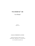
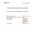
2.2 The SSR-1 Hardware
Main Connector
Channel Status
LEDs
Insert card as
shown in slot
beneath board.
Figure 1. Top View
MicroSD Card Slot
(push-push type connector)
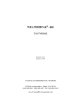
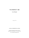
Coin Battery Holder
Figure 2. Bottom View
© 2015 Slerj, LLC
Insert battery
as shown.
This is the negative side of
the battery. It must make
contact with the printed
circuit board.
5
www.slerj.com
SSR-1 User’s Manual
Rev D, 18 May 2015
WARNING: Improper removal of the backup battery can damage the SSR-1. To
remove the battery, use a blunt stick to push the battery out of the holder.
DO NOT PRY OR PULL THE BATTERY.
CAUTION: Like most electronic components, the SSR-1 can be damaged by
electrostatic discharge. Observe typical precautions for handling electrostatic
discharge sensitive devices.
© 2015 Slerj, LLC
6
www.slerj.com
SSR-1 User’s Manual
Rev D, 18 May 2015
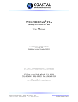
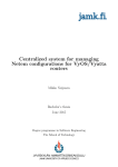
2.3 Connecting the SSR-1
The pins of the main connector are shown in Figure 3 and described in Table 1. The default
configuration of the SSR-1 provides access to the user shell (see Section 4 Interactive Shell, for
details) on channel 1 and causes channels 2 and 3 to record when the digital input command pin
(DI, pin 15) is pulled to ground. All channels default to 115200 baud, 8 data bits, no parity, and
1 stop bit.
WARNING: Channels 1 and 2 are RS-232 voltage level compatible, and channel 3
is 5 Volt tolerant, TTL compatible, 3.3V CMOS. Do not connect an RS-232 device
to channel 3 of the SSR-1.
Figure 3. Main Connector (View looking into the face of the connector)
Table 1. Main Connector Pins
Pin 1
1
2
3,7 2
4,8 2
11 3
12 4
16,18,20 3
ID
Vsup
Vret
T1,T2
R1,R2
T3
R3
Sx
15 4
17 4
19 4
DI
PI
res
1
2
3
4
Description
Supply voltage (4.5-32 VDC).
Supply return (tied to GND onboard the SSR-1).
Asynchronous serial transmitter output for channels 1 and 2.
Asynchronous serial receiver input for channels 1 and 2.
Asynchronous serial transmitter output for channel 3.
Asynchronous serial receiver input for channel 3.
Status indication for channel x. High level indicates that the channel is
recording.
Digital input record command.
PWM input record command.
Reserved.
See Section 7.1 Electrical for detailed electrical specifications.
RS-232 compatible.
3.3V CMOS output
5V tolerant, TTL compatible, 3.3V CMOS input. Internally pulled up to 3.3 VDC.
© 2015 Slerj, LLC
7
www.slerj.com
SSR-1 User’s Manual
Rev D, 18 May 2015
Wiring for a typical application is shown in Figure 4. The default SSR-1 configuration is
assumed. In the figure, channel 1 is connected to a standard PC serial port for shell access,
allowing configuration and file system operations via a terminal application on the PC. Channel
2 records data from an RS-232 device and channel 3 records data from a TTL compatible device
when the Close to Record switch is closed.
Figure 4. Typical application wiring using the default SSR-1 configuration
© 2015 Slerj, LLC
8
www.slerj.com
SSR-1 User’s Manual
Rev D, 18 May 2015
2.4 Using the SSR-1
The SSR-1 is shipped in default configuration, which sets all channels to 115200 baud, 8 data
bits, no parity, and 1 stop bit. Channels 2 and 3 are configured to record when DI is pulled low.
Channel 1 is configured to present the user shell.
On power up, the SSR-1 displays a boot loader announcement and device details. If a channel is
attached to the user shell, it will present the user shell prompt. A typical power-on sequence
would produce output similar to:
Slerj Boot Loader v1.0.0
MK:Slerj
HW:SSR1
MG:1608747
MD:SSR-1
SN:1
MV:22T
SSR-1 Shell
>
As an example of shell usage, consider changing the command source for channel 3 to +dig so
that the device records when the DI pin is high. In the following sequence, <enter> means
pressing the Enter/Return key to execute the command in the shell. With the SSR-1 shell
connected to a terminal program, type
config <enter>
to show the current SSR-1 configuration.
To change the command source for channel 3 to +dig, type
config 3 src +dig <enter>
Verify that the configuration has been changed using:
config 3 <enter>
To save the modified configuration in on-board non-volatile memory so that it is preserved
across power cycles, type:
config save <enter>
To confirm that the configuration has been saved, reboot the SSR-1 and verify configuration
using:
reset <enter>
config <enter>
Note that ‘cfg’ is an alias for ‘config’ and can be used as a shortcut.
© 2015 Slerj, LLC
9
www.slerj.com
SSR-1 User’s Manual
Rev D, 18 May 2015
3 Functional Overview
The SSR-1 consists of three asynchronous serial channels, a data recording subsystem, a user
interface module, a real-time clock, and digital input/output for status and control.
3.1 Serial Channels
The behavior of each serial channel is independent and is defined by a number of configurable
parameters:
Baud rate – 600 to 115200 baud, inclusive
Parity – Even, odd, or none
Stop – 1, 1.5 or 2 stop bits.
Echo – (Boolean) Echoes received characters out through the transmitter.
Function
o disabled – The channel is not used.
o record – The channel will record received data when commanded.
o shell – The channel will be tied to the interactive user shell function of the user
interface module.
o control – The channel will be tied to the control protocol function of the user
interface module.
Note that the user interface module can be attached only to a single channel. If one of the
channels is assigned to either the SHELL or CONTROL functions, no other channel may be
assigned to SHELL or CONTROL.
3.2 Record Function
In addition to the basic serial channel parameters above, when a channel is assigned to the
RECORD function, several other configurable parameters apply:
Command Source
Command Source determines how the channel is commanded to record. Options include
a discrete digital signal, a PWM signal, or software controlled through the user interface
module (shell or control protocol). Command Source for a channel can be set to one of
the following:
o -soft – The channel records when the Soft Command parameter (defined in the
next major bullet) is true. With -soft, the default for Soft Command at startup is
false. The DI and PI pins are ignored.
o +soft – The channel records when the Soft Command parameter is true.
With +soft, the default for Soft Command at startup is true. This selection for
Command Source causes the channel to automatically record at startup. The DI
and PI pins are ignored.
o -dig – The channel records when the digital input pin (DI) is low.
o +dig – The channel records when the digital input pin (DI) is high.
© 2015 Slerj, LLC
10
www.slerj.com
SSR-1 User’s Manual
Rev D, 18 May 2015
o -pwm – Recording starts when the pulse width on the pulse input pin (PI) is
1ms ± 250s. Recording stops when the pulse width on PI is 2ms ± 250s.
o +pwm – Recording starts when the pulse width on the pulse input pin (PI) is
2ms ± 250s. Recording stops when the pulse width on PI is 1ms ± 250s.
The PWM input is designed to work with the type of signal used by hobby servos.
The signal is considered valid when high going pulses are present with a pulse width
between 750s and 2250s, and a period of 4ms to 65ms. The current record state
for a channel using the PWM input is changed only when a valid PWM signal is
present that meets the requirements of the selected PWM Command Source (+pwm or
–pwm, specified above).
Both the DI and PI pins are 5 volt tolerant and internally pulled to 3.3V. See Section
7.1 Electrical for specifications.
Soft Command
Soft Command is a Boolean software parameter that determines whether the channel
records when the Command Source parameter is ±soft. The Soft Command parameter can
be set through the user interface module (interactive shell or control protocol).
File Type
The SSR-1 supports both raw and time tagged archives. When file type is raw, bytes are
written to file just as they are received. When file type is tt, bytes are encapsulated into a
file structure that associates a timestamp with received bytes. Bytes are stamped with a
resolution of 2ms. For details, see Section 6 Time Tagged Archives.
File Mode
Supported file creation modes are retry, overwrite, and append. When file mode is retry,
the SSR-1 will continue to retry the file creation operation until it succeeds. File creation
can fail if a file with the same name already exists. This mode is a useful complement to
user definable file paths (next bullet). Overwrite will cause an existing file to be replaced
by a newly commanded recording. Append will cause new data to be appended to an
existing file. For both overwrite and append modes, if the file specified by File Path does
not exist, it is created.
File Path
The File Path parameter holds a path template that specifies the name and location of the
file to be created when recording is commanded. A path template is a normal path string
that has replaceable fields defined in Table 2 below. A field is identified in the template
by a backslash followed by one of the field identifiers, or several consecutive identifiers
encapsulated in square brackets. For example, the path template /c[chms].dat would be
© 2015 Slerj, LLC
11
www.slerj.com
SSR-1 User’s Manual
Rev D, 18 May 2015
translated to the path /c1083000.dat for channel 1 if the time is 08:30:00 when a file is
created. Similarly, the path template /gps/nmea\4.txt would be replaced by
/gps/nmeaXXXX.txt where XXXX is a number that is incremented on each attempt to
open the file. Currently, path templates of up to 29 bytes are supported, and the resulting
path (with fields replaced) must be no more than 64 bytes.
Table 2. Path Template Field Codes
Field
Identifier
c*
Y
M
D
h
m
s*
t
y
X
d
2
3
4
*
Replaced With
channel number [1-3]
year [00-99]
month [01-12]
day [01-31]
hour [00-23]
minute [00-59]
second [00-59]
tenth of second [0-9]
year (4 digit) [2001-2099]
hex digit month [1-C]
day of year [001-366]
two digit sequence number [00-99]
three digit sequence number [000-999]
four digit sequence number [0000-9999]
This field identifier is lower case.
File Size
Starting with firmware version 1.0.3, the SSR-1 supports automatic file close and reopen
when a size (or time) threshold is reached. Threshold values of 1 MB, 2 MB, 4 MB,
8 MB, 16 MB, 32 MB, 64 MB, 128 MB, 256 MB, 512 MB, and 1024 MB are supported.
Additionally, the File Size parameter can be set to Hour, Day, or Week, causing new files
to be started based on time instead of size. By default, the File Size threshold is off, and
no automatic close/reopen operations are performed.
© 2015 Slerj, LLC
12
www.slerj.com
SSR-1 User’s Manual
Rev D, 18 May 2015
3.3 User Interface Module
The user interface module provides user access to file system operations, device status, and
configuration. The module can be assigned to only one serial channel and can be configured to
present either an interactive shell interface or the control protocol on that channel. More
information on the interactive shell and control protocol can be found in Sections 4 and 5,
respectively.
3.4 Real-Time Clock
The Real-Time Clock (RTC) maintains calendar time for the SSR-1. An on-board backup
battery (CR1220 or CR1216, Lithium 3V) allows the RTC to keep time across power cycles.
The RTC time is used to provide time stamps for the creation of files and is associated with the
free running system clock in time tagged archives.
3.5 Digital I/O
Digital input and output lines are provided for hardware access to recording control and status.
On the main connector, PI and DI provide record control as discussed in Section 3.2.
Additionally, a status line is provided for each channel (S1, S2, and S3) to indicate when the
channel is recording. Finally, a bi-color (red and green) status LED is provided on the SSR-1 for
each channel (Figure 1). The red segment illuminates when the corresponding channel is
recording. The green segment flashes to indicate reception of serial data on the channel.
In firmware 1.0.3, flash codes were added to make status of the SSR-1 plainly visible. The
following flash codes are implemented using the red LEDs.
Table 3. LED Flash Patterns
Status
READY1
Flash Pattern
Short flash every 4 seconds
CARD ERROR2
Long flash followed by two short
flashes every 2 seconds
CARD FULL2
Description
Indicates that a record channel is ready to
record when commanded.
Indicates that the card is missing or an
unrecoverable error has occurred.
Indicates that the card is full.
Two long flashes every 2 seconds
1
2
Presented only on channels configured to record.
Presented on all channel LEDs simultaneously.
© 2015 Slerj, LLC
13
www.slerj.com
SSR-1 User’s Manual
Rev D, 18 May 2015
4 Interactive Shell
The interactive shell is designed to provide easy access to the SD card file system, device status,
and configuration options. Entering ‘?’ or ‘help’ at the command prompt provides
information about using the shell. Each command can be followed by ‘?’ to retrieve help
information. Multiple commands can be separated by a semi-colon. All commands are case
sensitive. For example:
>cls ?
Usage: cls
Clears the screen.
Aliases: clear
>date;time
20130327
102840
>
The shell supports line editing and keeps a history of recently used commands. The ANSI
escape sequences shown in Table 4 are supported.
Table 4. Shell Line Editing Sequences
Keyboard Key
Up-arrow
Down-arrow
Home
End
Left-arrow
Right-arrow
Ctrl + Left-arrow
Ctrl + Right-arrow
1
Alternate
Sequence1
^p
^n
^a
^z
^k
^l
^b
^f
Function
Recall the previous command to the command line.
Recall the next command to the command line. This is only
available when up-arrow has been used to recall a previous
command.
Move the cursor to the start of the command line.
Move the cursor to the end of the command line.
Move the cursor left one character.
Move the cursor right one character.
Move the cursor left (backward) one word.
Move the cursor right (forward) one word.
The caret (^) indicates use of the Ctrl key with the letter.
In the description of individual commands below, the following conventions are used:
[ ] indicates optional parameters
{ } identifies a set of choices separated by | (choose one)
< > indicates a variable defined in the help text
© 2015 Slerj, LLC
14
www.slerj.com
SSR-1 User’s Manual
Rev D, 18 May 2015
4.1 System Commands
System commands provide access to general system functions including the real time clock and
operational status.
Table 5. System Commands
Command
cls
date [yyyymmdd]
Aliases
clear
help
reset
status
time
[hhmmss][ap]
?
stat
Description
Clears the screen.
Sets the current date to the year, month, and day specified. If no
date is specified, this command returns the current date.
Provides help for using the shell.
Performs a device reset.
Displays device status (date/time, inputs, record channels).
Sets the current time using the hour, minute, and second specified.
The hour is assumed to be in 24 hour format. However, the time
may be appended with an ‘a’ or ‘p’ to explicitly identify AM or PM
if a 12 hour format is used.
4.2 File Commands
File commands provide access to the SD card file system. FAT12, FAT16 and FAT32 volumes
are supported, and long filenames are supported on FAT32. Many file system commands require
a path. Both relative and absolute paths are supported in the shell. Directories are separated by a
forward slash (/).
Table 6. File Commands
Command
chdir <path>
del <path>
df
dir [path]
Aliases
cd
rm
mkdir <path>
pwd
ren <path1> <path2>
md
touch <path>
© 2015 Slerj, LLC
ls
mv,rn
Description
Changes the current working directory.
Removes a file or an empty directory.
Prints the volume size and free space -.
Lists the contents of a directory. If no path is provided, this
command lists the contents of the current directory.
Creates a directory.
Prints the current working directory.
Moves or renames a file or directory from path1 to path2.
[NOTE: Do not move open files]
Updates the timestamp on a file or directory.
15
www.slerj.com
SSR-1 User’s Manual
Rev D, 18 May 2015
4.3 Device Configuration
Device configuration is manipulated through the user interface module. The current working
configuration is held in system memory (RAM) and can be saved to non-volatile memory for
preservation across resets. On startup, if the contents of the non-volatile configuration memory
are valid, the stored configuration is loaded and used by the SSR-1. The shell provides access to
device configuration through the following commands:
Table 7. Configuration Commands
Command
config
config save
config load
config erase
config <ch#> [args]
Description
Prints the current configuration (including all channels).
Saves the working configuration to non-volatile memory.
Retrieves the stored configuration from non-volatile memory.
Erases the non-volatile configuration memory, but does not change the
current working configuration. When non-volatile configuration memory
has been erased, configuration defaults are loaded at startup.
Provides access to channel configuration. The parameter ch# is the channel
number (1 to 3). If no additional arguments are specified, this command
prints the configuration for the specified channel. Specific channel
configuration commands are in Table 8.
In addition to the global configuration commands presented in Table 7, there are several channel
specific configuration commands. The commands in the following table are entered as part of a
command line ‘config <ch#> command’.
Table 8. Channel Configuration Commands
Command
baud <rate>
parity { E | O | N | e | o | n }
stop { 1 | 1.5 | 2 }
echo <bool1>
Alias
function { record | disabled | shell |
control }
func
source [{ + | - }]2{ soft | dig | pwm }
soft <bool>
file type { raw | tt }
src
file mode { retry | append | overwrite }
file path <path>
© 2015 Slerj, LLC
16
Description
Sets baud to rate (600 to 115200).
Sets parity to even, odd, or none.
Sets the number of stop bits.
Enables echoing of received characters on the
channel.
Sets the configured function for the channel.
Note that the active function for a channel may
be different from the configured function (see
Section 4.4 Capturing the Shell).
Sets the channel command source.
Sets the channel soft command.
Selects between raw and time-tagged archives
for the channel.
Sets the channel file mode.
Sets the channel file path template to path. See
Section 3.2 Record Function for more
information on path templates.
www.slerj.com
SSR-1 User’s Manual
Rev D, 18 May 2015
Command
file size { off | 1 | 2 | 4 | 8 | 16 | 32 | 64 |
128 | 256 | 512 | 1024 | hour |
day | week }
Alias
Description
Sets the file size threshold. See Section 3.2
Record Function for more information on file
size thresholds.
1
bool denotes a Boolean expression, and may be specified using
{ y | Y | t | T | true | yes | on } for affirmative and { n | N | f | F | false | no | off } for negative.
2
The { + | - } prefix is optional. If not specified, + is assumed.
Note that multiple channel configuration commands may be specified together. For example, to
set the baud, parity and stop parameters of channel 2 with a single command, type
config 2 baud 38400 parity N stop 1
4.4 Capturing the Shell
To allow all channels to be used for recording without precluding use of the shell for
configuration, the shell can be captured by the user on startup on any channel. The design of this
feature is a compromise between conflicting requirements. Normal startups should be fast, and
the shell should prevent accidental capture. The capture mechanism operates prior to loading
stored configuration data, so all channels operate at 115200 baud, 8 bits, no parity, and 1 stop bit
for capture.
The process for capture is as follows:
On startup, the SSR-1 displays the boot loader message and device information.
The user optionally sends up to 5 lower case z characters followed by the string config.
All bytes in this sequence are echoed to the user. If any byte is received that is not part of
this sequence, or more than 800ms passes between bytes, the capture process is
terminated and the SSR-1 starts normally.
When the previous step has been completed, the SSR-1 will send a random challenge
string consisting of 4 upper case characters. The user must type those same characters in
lower case to complete the capture process. If the challenge string is not answered in 5
seconds, the capture process is aborted and the SSR-1 starts normally.
In order to support the capture feature, a distinction is made between the active function of a
channel and its configured function. The active function will mirror the configured function
when possible. Once the shell becomes the active function on a channel, the channel parameters
that affect communication (baud, parity, stop, and active function) are fixed until reset. Any
channel configuration options changed for the captured channel (and saved) will not take effect
until the next reset. If the shell was the configured function on a channel other than the captured
channel, the active function for that channel becomes disabled.
© 2015 Slerj, LLC
17
www.slerj.com
SSR-1 User’s Manual
Rev D, 18 May 2015
5 Control Protocol
In place of the interactive shell, the user interface module can provide access to control, status,
and configuration through a control protocol. This capability is provided to support robust
communication in machine automation environments. The notation used in this section is
intended to be familiar to C programmers. Values presented in hexadecimal are prepended
with 0x. The & symbol represents the bit-wise AND logical operation.
5.1 Message Format
Messages are exchanged between the SSR-1 and the user in the form of byte-oriented packets.
Each packet has a start sequence, an ID, a payload count, an optional payload, and a checksum.
Table 9. Control Protocol Message Format
Start1
0x81
Header
Start2
ID
0xA1 0xID
Count
0xNN
Payload
Payload
0xAA 0xBB …
0xZZ
Checksum
Cksum1 Cksum2
0xC1
0xC2
The start sequence for every packet is the same (0x81 0xA1), and is followed by a single ID
character. Count identifies the number of payload bytes that are included in the packet, and can
be zero. The checksum bytes represent a Fletcher checksum as defined in internet RFC 1145. It
is computed over the ID, Count, and payload bytes. The basic algorithm for computing the
checksum is:
unsigned char Cksum1=0;
unsigned char Cksum2=0;
unsigned char *p = (address of message ID);
int i=0;
while(i<number_of_payload_bytes+2)
{
Cksum1 = Cksum1 + p[i];
Cksum2 = Cksum2 + Cksum1;
i = i + 1;
}
Ordinarily, have a single byte to represent payload count would suggest that the maximum
possible payload length is 255 bytes. But since many applications may require longer packets,
the most significant bit (MSb) of the Count is given special significance in the control protocol.
When the MSb is set, the lower 7 bits are interpreted as a count of 8 byte blocks. Also, since
counts without the MSb set already provide coverage for payloads between 0 and 127 bytes, this
special function starts at 128 bytes. When the MSb of Count is set, payload length is calculated
as 128 + (Count&0x7F)*8.
© 2015 Slerj, LLC
18
www.slerj.com
SSR-1 User’s Manual
Rev D, 18 May 2015
For example, a Count of 0x80 would indicate a payload of 128 bytes. A Count of 0x81 would
indicate a payload length of 136 bytes. The longest payload supported by this implementation is
(Count = 0xFF) 1144 bytes. When the MSb of count is set, the payload length will be modulo 8.
In the control protocol, all multi-byte values are sent most significant byte first (i.e., big endian).
In this document, messages are divided into two groups: general messages and messages used to
set and query configuration. In the message definitions, types will be identified by the following
abbreviations shown in Table 10.
Table 10. Control Protocol Type Definitions
Type
U1
U2
U4
I1
I2
I4
Bx
BN
Description
Unsigned 8 bit integer
Unsigned 16 bit integer
Unsigned 32 bit integer
Signed 8 bit integer
Signed 16 bit integer
Signed 32 bit integer
String of x bytes
Variable length string of bytes
5.2 General Messages
General messages (Table 11) provide access to command functions and status of the SSR-1. All
general messages received by the SSR-1 will be answered with a message to acknowledge
(ACK), to negatively acknowledge (NACK), or to provide the requested data.
Table 11. General Control Protocol Messages
ID
0x10
0x11
0x20
0x21
0x22
0x24
0x30
0x30
0x31
0x31
0x50
0x51
0x99
1
Direction1
in
in
out
out
out
out
in
out
in
out
in
out
in
Description
Record
Stop
Command Status
Card Status
Disk Status
All Channel Status
Set Date
Date
Set Time
Time
Configuration Set
Configuration Query
Reset
Direction is from the SSR-1’s point of view
© 2015 Slerj, LLC
19
www.slerj.com
SSR-1 User’s Manual
Rev D, 18 May 2015
ACK messages have ID 0x90 with a single payload byte that is the message ID being
acknowledged. For example, an ACK for a Record message (ID=0x10) would comprise the
following:
Start1
0x81
Header
Start2
ID
0xA1 0x90
Count
0x01
Payload
Payload
0x10
Checksum
Cksum1 Cksum2
0xA1
0xC2
NACK responses to general messages have ID 0x91 and two payload bytes. The first payload
byte is the message ID that is being negatively acknowledged. The second payload byte
indicates the reason for the negative acknowledgement. For example, a NACK for a Record
message that was rejected because an invalid channel number (error code = 0x02) was specified
would be constructed as:
Start1
0x81
Header
Start2
ID
0xA1 0x91
Count
0x02
Payload
Payload
0x10 0x02
Checksum
Cksum1 Cksum2
0xA5
0x6C
For a list of error codes, see Section 5.4 Error Codes.
All general output messages (direction = out) must be polled by the user. A message is polled by
sending a message to the SSR-1 with the same message ID with zero payload. For example, to
poll the All Channel Status message (ID = 0x24), construct the poll message as follows:
Start1
0x81
Header
Start2
ID
0xA1 0x24
© 2015 Slerj, LLC
Count
0x00
Checksum
Cksum1 Cksum2
0x24
0x48
20
www.slerj.com
SSR-1 User’s Manual
Rev D, 18 May 2015
5.2.1 Record
Record
Message
Requests recording to start immediately on the specified channel.
Description
ID
Payload Length
Direction
Message Rate
0x10
1 to 30 bytes
in
Payload
Byte
Type
Notes
Name
Units
Purpose / Comment
Offset
0
U1
1
channel
Channel (1 – 3)
1
BN
2
path
Path Template to set prior to recording.
Notes:
1. The configured channel function must already be record. Otherwise, this command will have no
effect. This command sets the channel command source to +soft and sets the soft command to true.
2. Path is optional and may be omitted. In that case, recording will begin using the currently defined
path template.
Possible Replies:
ACK
NACK_INV_LEN
NACK_INV_CH
NACK_INV_PATH_LEN
NACK_PATH_SYNTAX
NACK_PATH_INV_TOKEN
NACK_PATH_SEQ
NACK_PATH_XLEN
5.2.2 Stop
Stop
Message
Requests the specified channel to stop recording immediately.
Description
ID
Payload Length
Direction
Message Rate
0x11
1 byte
in
Payload
Byte
Type
Notes
Name
Units
Purpose / Comment
Offset
0
U1
1
channel
Channel (1 – 3)
Notes:
1. The configured channel function must already be record. Otherwise, this command will have no
effect. This command sets the channel command source to +soft and sets the soft command to false.
Possible Replies:
ACK
NACK_INV_LEN
NACK_INV_CH
© 2015 Slerj, LLC
21
www.slerj.com
SSR-1 User’s Manual
Rev D, 18 May 2015
5.2.3 Command Status
Command Status
Message
Provides the status of the record command sources.
Description
ID
Payload Length
Direction
Message Rate
0x20
5 bytes
out
polled1
Payload
Byte
Type
Notes
Name
Units
Purpose / Comment
Offset
0
U1
status
bitfield Status:
bit 7: (reserved)
bit 6: channel 3 soft command
bit 5: channel 2 soft command
bit 4: channel 1 soft command
bit 3: (reserved)
bit 2: PWM input valid
bit 1: PWM input 2ms (as opposed to 1ms)
bit 0: digital input (DI pin) high
1
U2
width
PWM pulse width
sec
3
U2
period
PWM period
sec
Notes:
1. This message is polled by sending a message with ID=0x20 and no payload.
5.2.4 Card Status
Card Status
Message
Provides the status of the SD card as detected by the socket.
Description
ID
Payload Length
Direction
Message Rate
0x21
1 byte
out
polled1
Payload
Byte
Type
Notes
Name
Units
Purpose / Comment
Offset
0
U1
status
bitfield Status:
bits 7-3: (reserved)
bit 2: Card is write protected
bit 1: Card is not inserted
bit 0: Card is not initialized
Notes:
1. This message is polled by sending a message with ID=0x21 and no payload.
© 2015 Slerj, LLC
22
www.slerj.com
SSR-1 User’s Manual
Rev D, 18 May 2015
5.2.5 Disk Status
Disk Status
Message
Provides the status of the disk as detected by the file system.
Description
ID
Payload Length
Direction
Message Rate
0x22
8 bytes
out
polled1
Payload
Byte
Type
Notes
Name
Units
Purpose / Comment
Offset
0
U4
size
kB
Size of the disk
4
U4
free
kB
Unused disk space
Notes:
1. This message is polled by sending a message with ID=0x22 and no payload.
© 2015 Slerj, LLC
23
www.slerj.com
SSR-1 User’s Manual
Rev D, 18 May 2015
5.2.6 All Channel Status
All Channel Status
Message
Provides the status of all channels.
Description
ID
Payload Length
Direction
Message Rate
0x24
3 bytes
out
polled1
Payload
Byte
Type Notes
Name
Units
Purpose / Comment
Offset
0
U1
2
channel1
bitfield
Status:
bit 7: record is commanded
bit 6: (reserved)
bits 5-4: channel function
0 = disabled
1 = record
2 = control
3 = shell
bits 3-0: channel file state
0 = closed
1 = building path
2 = opening file
3 = recording
4 = path template translation error
5 = error building path
6 = error opening file
7 = disk error
8 = disk full
1
U1
channel2
bitfield
(see channel 1)
2
U1
channel3
bitfield
(see channel 1)
Notes:
1. This message is polled by sending a message with ID=0x24 and no payload.
2. File state 8 (disk full) was added in firmware 1.0.3.
© 2015 Slerj, LLC
24
www.slerj.com
SSR-1 User’s Manual
Rev D, 18 May 2015
5.2.7 Set Date
Set Date
Message
Sets the date.
Description
ID
Payload Length
Direction
Message Rate
0x30
4 bytes
in
Payload
Byte
Type Notes Name Units
Purpose / Comment
Offset
0
U2
year
Year (2001 – 2099)
2
U1
month
Month (1 – 12)
3
U1
day
Day of month (1 – 31)
Notes:
Possible Replies:
ACK
NACK_INV_LEN
NACK_INV_DATE
5.2.8 Date
Date
Message
Provides the date.
Description
ID
Payload Length
Direction
Message Rate
0x30
6 bytes
out
polled1
Payload
Byte
Type Notes Name Units
Purpose / Comment
Offset
0
U2
year
Year (2001 – 2099)
2
U1
month
Month (1 – 12)
3
U1
day
Day of month (1 – 31)
4
U1
doy
Day of year (1 – 366)
5
U1
wday
Weekday (0=Sunday, 1=Monday, … 6 = Saturday)
Notes:
1. This message is polled by sending a message with ID=0x30 and no payload.
© 2015 Slerj, LLC
25
www.slerj.com
SSR-1 User’s Manual
Rev D, 18 May 2015
5.2.9 Set Time
Set Time
Message
Sets the time.
Description
ID
0x31
Payload
Byte
Type
Notes
Offset
0
U1
1
U1
2
U1
Notes:
Payload Length
3 bytes
Name
hour
minute
second
Direction
in
Units
Message Rate
Purpose / Comment
Hour (0 – 23)
Minute (1 – 59)
Second (1 – 59)
Possible Replies:
ACK
NACK_INV_LEN
NACK_INV_TIME
5.2.10 Time
Time
Message
Provides the time.
Description
ID
Payload Length
Direction
Message Rate
0x31
5 bytes
out
polled1
Payload
Byte
Type
Notes
Name
Units
Purpose / Comment
Offset
0
U1
hour
Hour (0 – 23)
1
U1
minute
Minute (1 – 59)
2
U1
second
Second (1 – 59)
3
U2
msec
millisecond (0 – 999)
Notes:
1. This message is polled by sending a message with ID=0x31 and no payload.
© 2015 Slerj, LLC
26
www.slerj.com
SSR-1 User’s Manual
Rev D, 18 May 2015
5.2.11 Configuration Set
Configuration Set
Message
Provides access to configuration functions.
Description
ID
Payload Length
Direction
Message Rate
0x50
> 1 bytes
in
Payload
Byte
Type
Notes
Name
Units
Purpose / Comment
Offset
0
BN
1
payload
Payload to pass to the configuration
subsystem
Notes:
1. The payload is passed to a configuration subsystem that handles it as a configuration request.
Generally the first byte of the payload specifies the configuration action or item to be affected.
Details on the control protocol configuration subsystem are provided in Section 5.3 Configuration
Messages.
Possible Replies:
Depends on the payload. See Section 5.3 Configuration Messages for details.
5.2.12 Configuration Query
Configuration Query
Message
Provides access to configuration data.
Description
ID
Payload Length
Direction
Message Rate
0x51
1 byte
in
Payload
Byte
Type
Notes
Name
Units
Purpose / Comment
Offset
0
U1
item
Configuration item that is requested.
Notes:
Possible Replies:
NACK_INV_LEN
NACK_INV_CH
A Configuration Query Reply (Section 5.3.5 Query Channel Parameter)
© 2015 Slerj, LLC
27
www.slerj.com
SSR-1 User’s Manual
Rev D, 18 May 2015
5.2.13 Reset
Message
Description
ID
0x99
Notes:
Reset
Resets the SSR-1.
Payload Length
0 bytes
Direction
in
Message Rate
Possible Replies:
ACK
NACK_INV_LEN
© 2015 Slerj, LLC
28
www.slerj.com
SSR-1 User’s Manual
Rev D, 18 May 2015
5.3 Configuration Messages
The Control Protocol provides a packetized interface to the configuration of the SSR-1.
Operations are the same as those available through the shell. For an overview of configuring the
SSR-1, refer to Section 4.3 Device Configuration. The control protocol provides access to
configuration through the Configuration Set and Configuration Query messages. The payload of
these messages is passed to a configuration subsystem that handles the specific configuration
request identified by the message payload. Configuration subsystem operations are available to
load, save, and erase the non-volatile configuration memory, set channel parameters, and query
current channel parameters.
As with general messages, the SSR-1 replies to all configuration messages with
acknowledgement (ACK), negative acknowledgement (NACK), or the requested data. ACK
messages are returned in response to successful Configuration Set (ID=0x50) requests.
Start1
0x81
Header
Start2
ID
0xA1 0x90
Count
0x01
Payload
Payload
0x50
Checksum
Cksum1 Cksum2
0xE1
0x02
NACK messages can be provided in response to Configuration Set or Configuration Query
messages and will have the form
Start1
0x81
Header
Start2
ID
0xA1 0x91
Count
0x02
Payload
Payload
0x50 0xEC
0x81
0xA1
0x02
0x51 0xEC
0x91
Checksum
Cksum1 Cksum2
0xC1
0xC2
0xC1
0xC2
<= Config Set NACK
<= Config Query NACK
where 0xEC is an error code as defined in Section 5.4 Error Codes, and 0xC1 and 0xC2 are
appropriately calculated checksums.
© 2015 Slerj, LLC
29
www.slerj.com
SSR-1 User’s Manual
Rev D, 18 May 2015
5.3.1 Load
Load Configuration
Request
Loads the configuration data stored in non-volatile configuration memory.
Description
Configuration Set Message
Container
Configuration ID1
Payload Length2
Direction
0x01
1 bytes
in
Payload
Byte
Type
Notes
Name
Units
Purpose / Comment
Offset
0
U1
CID1
Configuration ID
Notes:
1. Configuration ID is the first byte of the payload in the Configuration Set or Query container
message.
2. Payload length is the length of the container message payload.
Possible Replies:
ACK
NACK_INV_LEN
NACK_INV_NV
5.3.2 Save
Save Configuration
Request
Stores the working configuration data in non-volatile configuration memory.
Description
Configuration Set Message
Container
Configuration ID1
Payload Length2
Direction
0x02
1 bytes
in
Payload
Byte
Type
Notes
Name
Units
Purpose / Comment
Offset
0
U1
CID1
Configuration ID
Notes:
1. Configuration ID is the first byte of the payload in the Configuration Set or Query container
message.
2. Payload length is the length of the container message payload.
Possible Replies:
ACK
NACK_INV_LEN
© 2015 Slerj, LLC
30
www.slerj.com
SSR-1 User’s Manual
Rev D, 18 May 2015
5.3.3 Erase
Erase Configuration
Request
Erases the non-volatile configuration memory.
Description
Configuration Set Message
Container
Configuration ID1
Payload Length2
Direction
0x03
1 bytes
in
Payload
Byte
Type
Notes
Name
Units
Purpose / Comment
Offset
0
U1
CID1
Configuration ID
Notes:
1. Configuration ID is the first byte of the payload in the Configuration Set or Query container
message.
2. Payload length is the length of the container message payload.
Possible Replies:
ACK
NACK_INV_LEN
© 2015 Slerj, LLC
31
www.slerj.com
SSR-1 User’s Manual
Rev D, 18 May 2015
5.3.4 Set Channel Parameter
5.3.4.1 Line
Set Line
Request
Sets all communication parameters of a channel.
Description
Configuration Set Message
Container
Configuration ID1
Payload Length2
Direction
0x10
5 bytes
in
Payload
Byte
Type
Notes
Name
Units
Purpose / Comment
Offset
0
U1
CID1
Configuration ID
1
U1
channel
Channel (1 – 3)
2
U1
line
Line Parameters:
bits 7-6: parity
0 = none
1 = odd
2 = even
bits 5-4: stop bits
0 = 1 stop bit
1 = 1.5 stop bits
2 = 2 stop bits
bits 3-0: (reserved)
3
U2
baud
baud/100 Baud rate (divided by 100).
Notes:
1. Configuration ID is the first byte of the payload in the Configuration Set or Query container
message.
2. Payload length is the length of the container message payload.
Possible Replies:
ACK
NACK_INV_LEN
NACK_INV_CH
NACK_INV_BAUD
NACK_INV_PARITY
NACK_INV_STOP
© 2015 Slerj, LLC
32
www.slerj.com
SSR-1 User’s Manual
Rev D, 18 May 2015
5.3.4.2 Baud
Set Baud
Request
Sets baud rate for a channel.
Description
Configuration Set Message
Container
Configuration ID1
Payload Length2
Direction
0x11
4 bytes
in
Payload
Byte
Type
Notes
Name
Units
Purpose / Comment
Offset
0
U1
CID1
Configuration ID
1
U1
channel
Channel (1 – 3)
2
U2
baud
baud/100 Baud rate (divided by 100).
Notes:
1. Configuration ID is the first byte of the payload in the Configuration Set or Query container
message.
2. Payload length is the length of the container message payload.
Possible Replies:
ACK
NACK_INV_LEN
NACK_INV_CH
NACK_INV_BAUD
© 2015 Slerj, LLC
33
www.slerj.com
SSR-1 User’s Manual
Rev D, 18 May 2015
5.3.4.3 Parity
Set Parity
Request
Sets parity for a channel.
Description
Configuration Set Message
Container
Configuration ID1
Payload Length2
0x12
3 bytes
Payload
Byte
Type
Notes
Name
Units
Offset
0
U1
CID1
1
U1
channel
2
U1
parity
Direction
in
Purpose / Comment
Configuration ID
Channel (1 – 3)
Parity:
bits 7-2: (reserved)
bits 1-0: parity
0 = none
1 = odd
2 = even
Notes:
1. Configuration ID is the first byte of the payload in the Configuration Set or Query container
message.
2. Payload length is the length of the container message payload.
Possible Replies:
ACK
NACK_INV_LEN
NACK_INV_CH
NACK_INV_PARITY
© 2015 Slerj, LLC
34
www.slerj.com
SSR-1 User’s Manual
Rev D, 18 May 2015
5.3.4.4 Stop
Set Stop
Request
Sets stop bits for a channel.
Description
Configuration Set Message
Container
Configuration ID1
Payload Length2
0x13
3 bytes
Payload
Byte
Type
Notes
Name
Units
Offset
0
U1
CID1
1
U1
channel
2
U1
stop
Direction
in
Purpose / Comment
Configuration ID
Channel (1 – 3)
Stop:
bits 7-2: (reserved)
bits 1-0: stop bits
0 = 1 stop bit
1 = 1.5 stop bits
2 = 2 stop bits
Notes:
1. Configuration ID is the first byte of the payload in the Configuration Set or Query container
message.
2. Payload length is the length of the container message payload.
Possible Replies:
ACK
NACK_INV_LEN
NACK_INV_CH
NACK_INV_STOP
© 2015 Slerj, LLC
35
www.slerj.com
SSR-1 User’s Manual
Rev D, 18 May 2015
5.3.4.5 Function
Set Function
Request
Sets a channel’s function.
Description
Configuration Set Message
Container
Configuration ID1
Payload Length2
0x20
3 bytes
Payload
Byte
Type
Notes
Name
Units
Offset
0
U1
CID1
1
U1
channel
2
U1
function
Direction
in
Purpose / Comment
Configuration ID
Channel (1 – 3)
Function:
bits 7-2: (reserved)
bits 1-0: function
0 = disabled
1 = record
2 = control
3 = shell
Notes:
1. Configuration ID is the first byte of the payload in the Configuration Set or Query container
message.
2. Payload length is the length of the container message payload.
Possible Replies:
ACK
NACK_INV_LEN
NACK_INV_CH
NACK_SHCTRL_TAKEN
© 2015 Slerj, LLC
36
www.slerj.com
SSR-1 User’s Manual
Rev D, 18 May 2015
5.3.4.6 Source
Set Source
Request
Sets a channel’s record command source.
Description
Configuration Set Message
Container
Configuration ID1
Payload Length2
Direction
0x21
3 bytes
in
Payload
Byte
Type
Notes
Name
Units
Purpose / Comment
Offset
0
U1
CID1
Configuration ID
1
U1
channel
Channel (1 – 3)
2
U1
source
Source:
bits 7-3: (reserved)
bits 2-0: source
0 = +soft (soft command, true on reset)
1 = -soft (soft command, false on reset)
2 = +dig (DI pin, record when high)
3 = -dig (DI pin, record when low)
4 = +pwm (PI pin, record when 2ms)
5 = -pwm (PI pin, record win 1ms)
Notes:
1. Configuration ID is the first byte of the payload in the Configuration Set or Query container
message.
2. Payload length is the length of the container message payload.
Possible Replies:
ACK
NACK_INV_LEN
NACK_INV_CH
NACK_INV_SOURCE
© 2015 Slerj, LLC
37
www.slerj.com
SSR-1 User’s Manual
Rev D, 18 May 2015
5.3.4.7 Soft Command
Set Soft Command
Request
Sets the value of a channel’s internal soft command.
Description
Configuration Set Message
Container
Configuration ID1
Payload Length2
Direction
0x22
3 bytes
in
Payload
Byte
Type
Notes
Name
Units
Purpose / Comment
Offset
0
U1
CID1
Configuration ID
1
U1
channel
Channel (1 – 3)
2
U1
soft
Soft Command:
bits 7-1: (reserved)
bit 0: soft command (0=false, 1 = true)
Notes:
1. Configuration ID is the first byte of the payload in the Configuration Set or Query container
message.
2. Payload length is the length of the container message payload.
Possible Replies:
ACK
NACK_INV_LEN
NACK_INV_CH
© 2015 Slerj, LLC
38
www.slerj.com
SSR-1 User’s Manual
Rev D, 18 May 2015
5.3.4.8 File Type
Set File Type
Request
Sets the type of archive that a channel will record (raw or time tagged).
Description
Configuration Set Message
Container
Configuration ID1
Payload Length2
Direction
0x30
3 bytes
in
Payload
Byte
Type
Notes
Name
Units
Purpose / Comment
Offset
0
U1
CID1
Configuration ID
1
U1
channel
Channel (1 – 3)
2
U1
type
File Type:
bits 7-1: (reserved)
bit 0: file type (0=raw, 1 = time tagged)
Notes:
1. Configuration ID is the first byte of the payload in the Configuration Set or Query container
message.
2. Payload length is the length of the container message payload.
Possible Replies:
ACK
NACK_INV_LEN
NACK_INV_CH
© 2015 Slerj, LLC
39
www.slerj.com
SSR-1 User’s Manual
Rev D, 18 May 2015
5.3.4.9 File Mode
Set File Mode
Request
Sets the file open mode used by a channel.
Description
Configuration Set Message
Container
Configuration ID1
Payload Length2
Direction
0x31
3 bytes
in
Payload
Byte
Type
Notes
Name
Units
Purpose / Comment
Offset
0
U1
CID1
Configuration ID
1
U1
channel
Channel (1 – 3)
2
U1
mode
File Mode:
bits 7-2: (reserved)
bits 1-0: file mode
0 = retry
1 = append
2 = overwrite
Notes:
1. Configuration ID is the first byte of the payload in the Configuration Set or Query container
message.
2. Payload length is the length of the container message payload.
Possible Replies:
ACK
NACK_INV_LEN
NACK_INV_CH
NACK_INV_FM
© 2015 Slerj, LLC
40
www.slerj.com
SSR-1 User’s Manual
Rev D, 18 May 2015
5.3.4.10 File Path
Set File Path
Request
Sets the path template used by a channel when recording.
Description
Configuration Set Message
Container
Configuration ID1
Payload Length2
Direction
0x33
3 to 31 bytes
in
Payload
Byte
Type
Notes
Name
Units
Purpose / Comment
Offset
0
U1
CID1
Configuration ID
1
U1
channel
Channel (1 – 3)
2
BN
3
path
File Path Template
Notes:
1. Configuration ID is the first byte of the payload in the Configuration Set or Query container
message.
2. Payload length is the length of the container message payload.
3. See Section 3.2 Record Function, for details on path templates.
Possible Replies:
ACK
NACK_INV_LEN
NACK_INV_CH
NACK_PATH_LEN
NACK_PATH_SYNTAX
NACK_PATH_TOKEN
NACK_PATH_SEQ
NACK_PATH_XLEN
© 2015 Slerj, LLC
41
www.slerj.com
SSR-1 User’s Manual
Rev D, 18 May 2015
5.3.4.11 File Size
Set File Size
Request
Sets the file size threshold used by a channel.
Description
Configuration Set Message
Container
Configuration ID1
Payload Length2
Direction
0x34
3 bytes
in
Payload
Byte
Type
Notes
Name
Units
Purpose / Comment
Offset
0
U1
CID1
Configuration ID
1
U1
channel
Channel (1 – 3)
2
U1
size
File Size:
bits 7-4: (reserved)
bits 3-0: file size
0 = off
1 = 1 MB
2 = 2 MB
3 = 4 MB
4 = 8 MB
5 = 16 MB
6 = 32 MB
7 = 64 MB
8 = 128 MB
9 = 256 MB
10 = 512 MB
11 = 1024 MB
12 = hour
13 = day
14 = week
15 = off
Notes:
1. Configuration ID is the first byte of the payload in the Configuration Set or Query container
message.
2. Payload length is the length of the container message payload.
Possible Replies:
ACK
NACK_INV_LEN
NACK_INV_CH
© 2015 Slerj, LLC
42
www.slerj.com
SSR-1 User’s Manual
Rev D, 18 May 2015
5.3.5 Query Channel Parameter
Queries to the configuration subsystem are performed using Configuration Query messages.
When a valid query is received, the SSR-1 replies with a Configuration Query Reply.
Configuration Reply uses the same message ID (0x51) as the Configuration Query. The payload
of the reply depends on the request, and available configuration items are listed below.
5.3.5.1 Line
Line
Item
Provides all communication parameters of a channel.
Description
Configuration Query Reply Message
Container
Configuration ID1
Payload Length2
Direction
Message Rate
0x10
5 bytes
out
polled3
Payload
Byte
Type
Notes
Name
Units
Purpose / Comment
Offset
0
U1
CID1
Configuration ID
1
U1
channel
Channel (1 – 3)
2
U1
line
Line Parameters:
bits 7-6: parity
0 = none
1 = odd
2 = even
bits 5-4: stop bits
0 = 1 stop bit
1 = 1.5 stop bits
2 = 2 stop bits
bits 3-0: (reserved)
3
U2
baud
baud/100 Baud rate (divided by 100).
Notes:
1. Configuration ID is the first byte of the payload in the Configuration Query Reply container
message.
2. Payload length is the length of the container message payload.
3. This message is polled using a Configuration Query message with a two byte payload (this
Configuration ID and the channel number).
© 2015 Slerj, LLC
43
www.slerj.com
SSR-1 User’s Manual
Rev D, 18 May 2015
5.3.5.2 Baud
Baud
Item
Provides baud rate for a channel.
Description
Configuration Query Reply Message
Container
Configuration ID1
Payload Length2
Direction
Message Rate
0x11
4 bytes
out
polled3
Payload
Byte
Type
Notes
Name
Units
Purpose / Comment
Offset
0
U1
CID1
Configuration ID
1
U1
channel
Channel (1 – 3)
2
U2
baud
baud/100 Baud rate (divided by 100).
Notes:
1. Configuration ID is the first byte of the payload in the Configuration Query Reply container
message.
2. Payload length is the length of the container message payload.
3. This message is polled using a Configuration Query message with a two byte payload (this
Configuration ID and the channel number).
5.3.5.3 Parity
Parity
Item
Provides parity for a channel.
Description
Configuration Query Reply Message
Container
Configuration ID1
Payload Length2
0x12
3 bytes
Payload
Byte
Type
Notes
Name
Units
Offset
0
U1
CID1
1
U1
channel
2
U1
parity
Direction
out
Message Rate
polled3
Purpose / Comment
Configuration ID
Channel (1 – 3)
Parity:
bits 7-2: (reserved)
bits 1-0: parity
0 = none
1 = odd
2 = even
Notes:
1. Configuration ID is the first byte of the payload in the Configuration Query Reply container
message.
2. Payload length is the length of the container message payload.
3. This message is polled using a Configuration Query message with a two byte payload (this
Configuration ID and the channel number).
© 2015 Slerj, LLC
44
www.slerj.com
SSR-1 User’s Manual
Rev D, 18 May 2015
5.3.5.4 Stop
Stop
Item
Provides stop bits for a channel.
Description
Configuration Query Reply Message
Container
Configuration ID1
Payload Length2
0x13
3 bytes
Payload
Byte
Type
Notes
Name
Units
Offset
0
U1
CID1
1
U1
channel
2
U1
stop
Direction
out
Message Rate
polled3
Purpose / Comment
Configuration ID
Channel (1 – 3)
Stop:
bits 7-2: (reserved)
bits 1-0: stop bits
0 = 1 stop bit
1 = 1.5 stop bits
2 = 2 stop bits
Notes:
1. Configuration ID is the first byte of the payload in the Configuration Query Reply container
message.
2. Payload length is the length of the container message payload.
3. This message is polled using a Configuration Query message with a two byte payload (this
Configuration ID and the channel number).
© 2015 Slerj, LLC
45
www.slerj.com
SSR-1 User’s Manual
Rev D, 18 May 2015
5.3.5.5 Function
Function
Item
Provides a channel’s function.
Description
Configuration Query Reply Message
Container
Configuration ID1
Payload Length2
0x20
3 bytes
Payload
Byte
Type
Notes
Name
Units
Offset
0
U1
CID1
1
U1
channel
2
U1
function
Direction
out
Message Rate
polled3
Purpose / Comment
Configuration ID
Channel (1 – 3)
Function:
bits 7-2: (reserved)
bits 1-0: function
0 = disabled
1 = record
2 = control
3 = shell
Notes:
1. Configuration ID is the first byte of the payload in the Configuration Query Reply container
message.
2. Payload length is the length of the container message payload.
3. This message is polled using a Configuration Query message with a two byte payload (this
Configuration ID and the channel number).
© 2015 Slerj, LLC
46
www.slerj.com
SSR-1 User’s Manual
Rev D, 18 May 2015
5.3.5.6 Source
Source
Item
Provides a channel’s record command source.
Description
Configuration Query Reply Message
Container
Configuration ID1
Payload Length2
Direction
Message Rate
0x21
3 bytes
out
polled3
Payload
Byte
Type
Notes
Name
Units
Purpose / Comment
Offset
0
U1
CID1
Configuration ID
1
U1
channel
Channel (1 – 3)
2
U1
source
Source:
bits 7-3: (reserved)
bits 2-0: source
0 = +soft (soft command, true on reset)
1 = -soft (soft command, false on reset)
2 = +dig (DI pin, record when high)
3 = -dig (DI pin, record when low)
4 = +pwm (PI pin, record when 2ms)
5 = -pwm (PI pin, record win 1ms)
Notes:
1. Configuration ID is the first byte of the payload in the Configuration Query Reply container
message.
2. Payload length is the length of the container message payload.
3. This message is polled using a Configuration Query message with a two byte payload (this
Configuration ID and the channel number).
© 2015 Slerj, LLC
47
www.slerj.com
SSR-1 User’s Manual
Rev D, 18 May 2015
5.3.5.7 Soft Command
Soft Command
Item
Provides the value of a channel’s internal soft command.
Description
Configuration Query Reply Message
Container
Configuration ID1
Payload Length2
Direction
Message Rate
0x22
3 bytes
out
polled3
Payload
Byte
Type
Notes
Name
Units
Purpose / Comment
Offset
0
U1
CID1
Configuration ID
1
U1
channel
Channel (1 – 3)
2
U1
soft
Soft Command:
bits 7-1: (reserved)
bit 0: soft command (0=false, 1 = true)
Notes:
1. Configuration ID is the first byte of the payload in the Configuration Query Reply container
message.
2. Payload length is the length of the container message payload.
3. This message is polled using a Configuration Query message with a two byte payload (this
Configuration ID and the channel number).
5.3.5.8 File Type
File Type
Item
Provides the type of archive that a channel will record (raw or time tagged).
Description
Configuration Query Reply Message
Container
Configuration ID1
Payload Length2
Direction
Message Rate
0x30
3 bytes
out
polled3
Payload
Byte
Type
Notes
Name
Units
Purpose / Comment
Offset
0
U1
CID1
Configuration ID
1
U1
channel
Channel (1 – 3)
2
U1
type
File Type:
bits 7-1: (reserved)
bit 0: file type (0=raw, 1 = time tagged)
Notes:
1. Configuration ID is the first byte of the payload in the Configuration Query Reply container
message.
2. Payload length is the length of the container message payload.
3. This message is polled using a Configuration Query message with a two byte payload (this
Configuration ID and the channel number).
© 2015 Slerj, LLC
48
www.slerj.com
SSR-1 User’s Manual
Rev D, 18 May 2015
5.3.5.9 File Mode
File Mode
Item
Provides the file open mode used by a channel.
Description
Configuration Query Reply Message
Container
Configuration ID1
Payload Length2
Direction
Message Rate
0x31
3 bytes
out
polled3
Payload
Byte
Type
Notes
Name
Units
Purpose / Comment
Offset
0
U1
CID1
Configuration ID
1
U1
channel
Channel (1 – 3)
2
U1
mode
File Mode:
bits 7-2: (reserved)
bits 1-0: file mode
0 = retry
1 = append
2 = overwrite
Notes:
1. Configuration ID is the first byte of the payload in the Configuration Query Reply container
message.
2. Payload length is the length of the container message payload.
3. This message is polled using a Configuration Query message with a two byte payload (this
Configuration ID and the channel number).
5.3.5.10 File Path
File Path
Item
Provides the path template used by a channel when recording.
Description
Configuration Query Reply Message
Container
Configuration ID1
Payload Length2
Direction
Message Rate
0x33
3 to 31 bytes
out
polled3
Payload
Byte
Type
Notes
Name
Units
Purpose / Comment
Offset
0
U1
CID1
Configuration ID
1
U1
channel
Channel (1 – 3)
2
BN
4
path
File Path Template
Notes:
1. Configuration ID is the first byte of the payload in the Configuration Query Reply container
message.
2. Payload length is the length of the container message payload.
3. This message is polled using a Configuration Query message with a two byte payload (this
Configuration ID and the channel number).
4. See Section 3.2 Record Function, for details on path templates.
© 2015 Slerj, LLC
49
www.slerj.com
SSR-1 User’s Manual
Rev D, 18 May 2015
5.3.5.11 File Size
File Size
Item
Provides the file size threshold used by a channel.
Description
Configuration Query Reply Message
Container
Configuration ID1
Payload Length2
Direction
Message Rate
0x34
3 bytes
out
polled3
Payload
Byte
Type
Notes
Name
Units
Purpose / Comment
Offset
0
U1
CID1
Configuration ID
1
U1
channel
Channel (1 – 3)
2
U1
size
File Size:
bits 7-4: (reserved)
bits 3-0: file size
0 = off
1 = 1 MB
2 = 2 MB
3 = 4 MB
4 = 8 MB
5 = 16 MB
6 = 32 MB
7 = 64 MB
8 = 128 MB
9 = 256 MB
10 = 512 MB
11 = 1024 MB
12 = hour
13 = day
14 = week
15 (not used)
Notes:
1. Configuration ID is the first byte of the payload in the Configuration Query Reply container
message.
2. Payload length is the length of the container message payload.
3. This message is polled using a Configuration Query message with a two byte payload (this
Configuration ID and the channel number).
© 2015 Slerj, LLC
50
www.slerj.com
SSR-1 User’s Manual
Rev D, 18 May 2015
5.4 Error Codes
The control protocol provides a unified set of error codes to simplify interpreting and displaying
errors to the user. The possible error codes are listed in Table 12.
Table 12. Control Protocol Error Codes
Value
1
2
3
Name
NACK_INV_LEN
NACK_INV_CH
NACK_INV_NV
4
5
6
7
8
9
NACK_INV_DATE
NACK_INV_TIME
NACK_INV_BAUD
NACK_INV_PARITY
NACK_INV_STOP
NACK_SHCTRL_TAKEN
10
11
12
13
14
15
NACK_INV_SOURCE
NACK_INV_FM
NACK_PATH_LEN
NACK_PATH_SYNTAX
NACK_PATH_INV_TOKEN
NACK_PATH_SEQ
16
NACK_PATH_XLEN
17
18
19
NACK_SD_DISK_ERR
NACK_SD_INT_ERR
NACK_SD_NOT_READY
20
21
22
23
24
25
NACK_SD_INV_DRIVE
NACK_SD_NOT_ENABLED
NACK_SD_NO_FS
NACK_SD_TIMEOUT
NACK_SD_UNKNOWN
NACK_UNKNOWN
© 2015 Slerj, LLC
Description
The message does not have the expected length.
An invalid channel number was provided. Must be 1 to 3.
The non-volatile configuration memory contents are
invalid.
The date is invalid.
The time is invalid.
The baud rate is invalid (outside min / max allowed)
The parity is invalid.
The stop bit value is invalid.
The shell or control function is already assigned to another
channel. It cannot be assigned to more than one channel.
The record command source is invalid.
The file mode is invalid.
The path template is too long.
The path has a syntax error.
The path has an unrecognized template field code.
A sequence field code was used in a directory name, and
is only valid in a file name.
The translated path is too long after replacing all field
codes.
File system disk error
File system internal error
The file system is not ready (card not present or not
initialized).
(not currently used)
(not currently used)
No file system was found on the card.
A timeout occurred when accessing the card.
Unknown file system or card error.
The request was not recognized.
51
www.slerj.com
SSR-1 User’s Manual
Rev D, 18 May 2015
6 Time Tagged Archives
Often, it is important to know not only what serial data was transferred, but when it was
transferred. This is useful in both the analysis of communication systems and in the ability to
reconstruct streams as they originally occurred. The SSR-1 supports time tagged archives, in
which received bytes are tagged with the time they were received. When a channel is configured
to record time tagged archives, the received bytes are encapsulated in packets prior to being
written to the file system. Two types of packets are currently defined: the data packet and a time
correlation packet. All multi-byte words in the archive are big endian.
Note that a software utility, including source code, is provided with the SSR-1 for parsing time
tagged archives into a variety of useful formats. See section 6.3 The STTP Utility for details.
6.1 Data Packet
The data packet uses the system free running clock as the time stamp source. Bytes are grouped
into 2ms windows for stamping. Each data packet begins with a base time stamp that identifies
the whole second in which the data was collected. The base time stamp is followed by a series of
frames that are composed of an incremental time stamp (fractional second within the base time
stamp window) and a group of bytes that were received during the increment. The data packet is
terminated by a Fletcher checksum as defined in section 5.1 Message Format.
Table 13. Time Tagged Data Packet
Element
Bytes Description
Packet Header
2
Packet start sequence.
0x82 0xA2
Run Time
4
Current run time in seconds.
Frame repeated until an mSec_Count value of 0xFFFF is encountered.
Fractional second and number of bytes for this frame.
mSec_Count
2
bits 15-7: milliseconds / 2
bits 6-0: number of bytes to follow (n)
The n bytes that were received in the time window leading up to this
Data
n
packet frame.
End Sequence
2
0xFFFF (invalid mSec_Count)
Fletcher checksum calculated between Run Time and End Sequence,
Checksum
2
inclusive.
© 2015 Slerj, LLC
52
www.slerj.com
SSR-1 User’s Manual
Rev D, 18 May 2015
6.2 Time Correlation Packet
The time correlation packet associates the free running clock timer with the real time clock. A
time correlation packet is written when the recording is started, every 10 minutes, and as the
recording is stopped.
Table 14. Time Tagged Time Correlation Packet
Element
Packet Header
0x82 0xA3
Run Time
Bytes
Description
2
Packet start sequence.
4
Current run time in milliseconds.
Real Time Clock
word 0:
bits 15-4: year (2001 – 2099)
bits 3-0: month (1 – 12)
word 1:
bits 15-11: day (1 – 31)
bits 10-6: hour (0 – 23)
bits 5-0: minute (0 – 59)
word 2:
bits 15-10: second (0 – 59)
bits 9-0: milliseconds (0 – 999)
Fletcher checksum calculated between Run Time and RTC Time, inclusive.
RTC Time
6
Checksum
2
6.3 The STTP Utility
The SLERJ Time Tagged Parser is a Windows command line utility (sttp.exe) provided with the
SSR-1 to parse time tagged archives into various output types. Given a time tagged archive, the
utility can produce the original raw stream (with no timing information), a time tagged
correlation packet file, a data packet file that has a line for each frame, and a mixed file that
interlaces time correlation packets with data packets. Additionally, version 1.1 of the STTP
utility (available at the Slerj website), is able to directly generate time stamped line output from
archives that contain recordings of line-oriented serial data. See Application Note AN002 –
STTP Timestamped Lines for details.
All of the non-raw outputs are space delimited text files. Data bytes are represented as a series
of hexadecimal text characters. An example of each of the textual output files is below. Usage
of the sttp utility is summarized by its help output:
usage: sttp.exe [options] <infile>
options:
-h Include headers in tcp and dat files.
-r <raw_file> Write raw stream data to raw_file
-t <tcp_file> Write Time Correlation Packets to tcp_file
-d <dat_file> Write Tagged data to dat_file
-m <mxd_file> Write both TCPs and tagged data to mxd_file
© 2015 Slerj, LLC
53
www.slerj.com
SSR-1 User’s Manual
Rev D, 18 May 2015
Time Correlation Packet output example:
RunTime(ms) Year Month Day Hour Minute Second
4196 2013 3 25 9 52 4.625
604196 2013 3 25 10 2 3.628
1204196 2013 3 25 10 12 2.486
Tagged Data output example:
RunTime(ms) count HexBytes
4196 20 322E323530333630652B303520322E3339343433
4198 23 30652D3034202D312E343530303639652D303420322E37
4200 23 3637343235652D303420312E373134373036652D303120
Mixed output example:
A3
A2
A2
…
A2
A3
A2
4196 2013 3 25 9 52 4.625
4196 20 322E323530333630652B303520322E3339343433
4198 23 30652D3034202D312E343530303639652D303420322E37
604194 23 3032202D352E353633313634652D303120312E32323636
604196 2013 3 25 10 2 3.628
604196 23 3330652D303220332E313334343333652B303020302037
© 2015 Slerj, LLC
54
www.slerj.com
SSR-1 User’s Manual
Rev D, 18 May 2015
7 Specifications
7.1 Electrical
Min
4.5
Supply Voltage
Supply Current
Idle1
Recording2
Idle1
Recording2
Idle1
Recording2
Typical
Max
32
5 VDC Supply
30
90
12 VDC Supply
14
38
24 VDC Supply
9
21
Unit
VDC
mA
mA
mA
mA
mA
mA
Digital Input Characteristics
(Channel 3 Rx, DI, PI, Res)
Low level input voltage
1.37
V
High level input voltage
1.85
V
Schmitt trigger hysteresis
100
mV
Weak pull-up equivalent resistor
25
40
55
k
Digital Output Characteristics
(Channel 3 Tx, S1-S3)
Low level output voltage (±8mA)
0.4
V
High level output voltage (±8mA)
2.9
V
Low level output voltage (±20mA)
1.3
V
High level output voltage (±20mA)
2.0
V
RS-232 Transmitter Characteristics
(Channels 1 and 2)
Transmitter Output Voltage Range
-13.2
13.2
V
±5
V
Transmitter Output Voltage into 3k Load
RS-232 Receiver Characteristics
(Channels 1 and 2)
Receiver Input Voltage Range
-25
25
V
Positive going input threshold voltage
1.5
2.4
V
Negative going input threshold voltage
0.6
1.2
V
1
SanDisk 4GB Class 4 microSDHC card inserted, but no data being received.
2
SanDisk 4GB Class 4 microSDHC card inserted, recording three full streams at 115200 baud.
© 2015 Slerj, LLC
55
www.slerj.com
SSR-1 User’s Manual
Rev D, 18 May 2015
7.2 Mechanical
Mounting holes designed for #2 hardware
Main Connector: Molex 87833-2020
Mating Connector: Molex 87568-2093
Battery: CR1220 or CR1216, 3V button cell
© 2015 Slerj, LLC
56
www.slerj.com
SSR-1 User’s Manual
Rev D, 18 May 2015
8 Revision History
Date
Rev.
8 May 2013
17 Jan 2014
Changes
Initial release
A
Added warning regarding battery removal.
Added caution regarding ESD precautions.
Restructured Table 1 to clarify pin electrical characteristics.
Clarified the description of command sources in 3.2 Record Function.
Clarified the control protocol description in 5 Control Protocol.
Corrected the truncated/missing text in the description of the control protocol Count field
in 5.1 Message Format.
Corrected the footnote in the Query Channel Parameter message tables in Section 5.3.5
regarding how to poll each message.
Corrected the description of Run Time in Table 14. Time Tagged Time Correlation
Packet. The Run Time value in this packet is in milliseconds, not seconds.
Separated digital input and output in Section 7.1 Electrical to clarify specifications and
provide more details.
Removed shading from tables to prevent problems with PDF generation.
Other minor typographical and clarification edits.
26 March 2014
B
Updated document date/revision markings and table of content for new sections
Documentation added for firmware 1.0.3:
Added File Size threshold (Section 3.2 Record Function)
Added Flash Codes in Section 3.5 Digital I/O.
Added file size command in Table 8. Channel Configuration Commands.
Added disk full channel file state to 5.2.6 All Channel Status message.
Added File Size set/query messages (5.3.4.11 and 5.3.5.11)
5 May 2014
C
Updated photos to match Rev A hardware. See Product Change Notice PCN_14-01.
18 May 2015
D
Added example wiring diagram to section 2.3 Connecting the SSR-1
Added example shell session to section 2.4 Using the SSR-1
Clarified the Soft Command parameter in section 3.2 Record Function
Referenced the STTP version 1.1 and AN002 in section 6.3The STTP Utility
Added dimensions drawing to section 7.2 Mechanical
General cleanup of typos and wording.
© 2015 Slerj, LLC
57
www.slerj.com