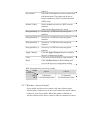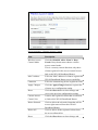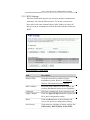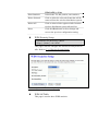
1
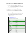
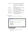
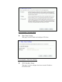
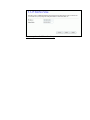
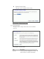
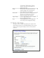
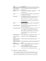
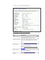
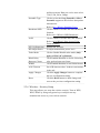
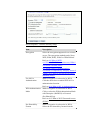
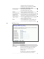
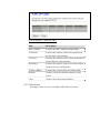
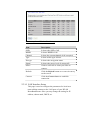
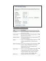
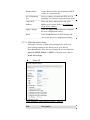
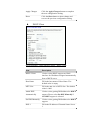
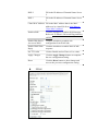
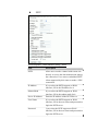
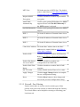
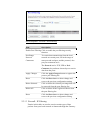
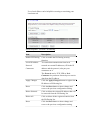
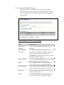
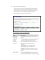
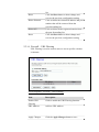
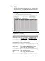
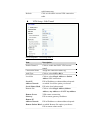
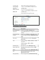
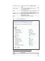
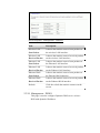
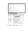
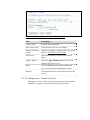
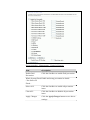
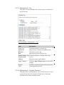
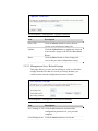
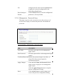
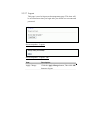
AWAP602HW
1 x WAN + 1 x LAN
802.11bg High-Power Wireless AP/Router
USER MANUAL
1 Installation
1.1 Hardware Installation
Step 1: Place the Wireless LAN Broadband Router to the best optimum
transmission location. The best transmission location for your
WLAN Broadband Router is usually at the geographic center of
your wireless network, with line of sign to all of your mobile
stations.
Step 2: Connect the WLAN Broadband Router to your wired network.
Connect the Ethernet WAN interface of WLAN Broadband Router
by category 5 Ethernet cable to your switch/ hub/ xDSL modem or
cable modem. A straight-through Ethernet cable with appropriate
cable length is needed.
Step 3: Supply DC power to the WLAN Broadband Router. Use only the
AC/DC power adapter supplied with the WLAN Broadband Router;
it may occur damage by using a different type of power adapter.
The hardware installation finished.
1.2 Software Installation
¾
There are no software drivers, patches or utilities installation needed,
but only the configuration setting. Please refer to chapter 3 for software
configuration.
Notice: It will take about 55 seconds to complete the boot up sequence
after powered on the WLAN Broadband Router; Power LED
will be active, and after that the WLAN Activity LED will be
flashing to show the WLAN interface is enabled and working
now.
2 Software configuration
There are web based management and configuration functions allowing you to
have the jobs done easily.
The WLAN Broadband Router is delivered with the following factory default
parameters on the Ethernet LAN interfaces.
Default IP Address: 192.168.1.250
Default IP subnet mask: 255.255.255.0
WEB login User Name: admin
WEB login Password: 12345
2.1 Prepare your PC to configure the WLAN Broadband Router
For OS of Microsoft Windows 95/ 98/ Me:
1. Click the Start button and select Settings, then click Control Panel. The
Control Panel window will appear.
2.
3.
4.
5.
6.
7.
Note: Windows Me users may not see the Network control panel. If so,
select View all Control Panel options on the left side of the window
Move mouse and double-click the right button on Network icon. The
Network window will appear.
Check the installed list of Network Components. If TCP/IP is not
installed, click the Add button to install it; otherwise go to step 6.
Select Protocol in the Network Component Type dialog box and click
Add button.
Select TCP/IP in Microsoft of Select Network Protocol dialog box then
click OK button to install the TCP/IP protocol, it may need the Microsoft
Windows CD to complete the installation. Close and go back to Network
dialog box after the TCP/IP installation.
Select TCP/IP and click the properties button on the Network dialog
box.
Select Specify an IP address and type in values as following example.
9
IP Address: 192.168.1.1, any IP address within 192.168.1.1 to
192.168.1.253 is good to connect the Wireless LAN Access Point.
9 IP Subnet Mask: 255.255.255.0
8. Click OK and reboot your PC after completes the IP parameters setting.
For OS of Microsoft Windows 2000, XP:
1. Click the Start button and select Settings, then click Control Panel. The
Control Panel window will appear.
2. Move mouse and double-click the right button on Network and Dial-up
Connections icon. Move mouse and double-click the Local Area
Connection icon. The Local Area Connection window will appear.
Click Properties button in the Local Area Connection window.
3. Check the installed list of Network Components. If TCP/IP is not
installed, click the Add button to install it; otherwise go to step 6.
4. Select Protocol in the Network Component Type dialog box and click
Add button.
5. Select TCP/IP in Microsoft of Select Network Protocol dialog box then
click OK button to install the TCP/IP protocol, it may need the Microsoft
Windows CD to complete the installation. Close and go back to Network
dialog box after the TCP/IP installation.
6. Select TCP/IP and click the properties button on the Network dialog
box.
7. Select Specify an IP address and type in values as following example.
9
IP Address: 192.168.1.1, any IP address within 192.168.1.1 to
192.168.1.253 is good to connect the Wireless LAN Access Point.
9 IP Subnet Mask: 255.255.255.0
8. Click OK to completes the IP parameters setting.
For OS of Microsoft Windows NT:
1. Click the Start button and select Settings, then click Control Panel. The
Control Panel window will appear.
2. Move mouse and double-click the right button on Network icon. The
Network window will appear. Click Protocol tab from the Network
window.
3. Check the installed list of Network Protocol window. If TCP/IP is not
installed, click the Add button to install it; otherwise go to step 6.
4. Select Protocol in the Network Component Type dialog box and click
Add button.
5. Select TCP/IP in Microsoft of Select Network Protocol dialog box then
click OK button to install the TCP/IP protocol, it may need the Microsoft
Windows CD to complete the installation. Close and go back to Network
dialog box after the TCP/IP installation.
6. Select TCP/IP and click the properties button on the Network dialog
box.
7. Select Specify an IP address and type in values as following example.
9
IP Address: 192.168.1.1, any IP address within 192.168.1.1 to
192.168.1.253 is good to connect the Wireless LAN Access Point.
9 IP Subnet Mask: 255.255.255.0
8. Click OK to complete the IP parameters setting.
2.2 Connect to the WLAN Broadband Router
Open a WEB browser, i.e. Microsoft Internet Explore, then enter
192.168.1.254 on the URL to connect the WLAN Broadband Router.
2.3 Management and configuration on the WLAN Broadband Router
2.3.1 Status
This page shows the current status and some basic settings of the
device, includes system, wireless, Ethernet LAN and WAN
configuration information.
Screen snapshot – Status
Item
Description
System
Uptime
It shows the duration since WLAN
Broadband Router is powered on.
Firmware version
It shows the firmware version of WLAN
Broadband Router.
Wireless configuration
Mode
It shows wireless operation mode
Band
It shows the current wireless operating
frequency.
SSID
It shows the SSID of this WLAN Broadband
Router.
The SSID is the unique name of WLAN
Broadband Router and shared among its
service area, so all devices attempts to join
the same wireless network can identify it.
Channel Number
It shows the wireless channel connected
currently.
Encryption
It shows the status of encryption function.
BSSID
It shows the BSSID address of the WLAN
Broadband Router. BSSID is a six-byte
address.
Associated Clients
It shows the number of connected clients (or
stations, PCs).
TCP/IP configuration
Attain IP Protocol
It shows type of connection.
IP Address
It shows the IP address of LAN interfaces of
WLAN Broadband Router.
Subnet Mask
It shows the IP subnet mask of LAN
interfaces of WLAN Broadband Router.
Default Gateway
It shows the default gateway setting for LAN
interfaces outgoing data packets.
DHCP Server
It shows the DHCP server is enabled or not.
MAC Address
It shows the MAC address of LAN interfaces
of WLAN Broadband Router.
WAN configuration
Attain IP Protocol
It shows how the WLAN Broadband Router
gets the IP address. The IP address can be set
manually to a fixed one or set dynamically by
DHCP server or attain IP by PPPoE / PPTP
connection.
IP Address
It shows the IP address of WAN interface of
WLAN Broadband Router.
Subnet Mask
It shows the IP subnet mask of WAN
interface of WLAN Broadband Router.
Default Gateway
It shows the default gateway setting for WAN
interface outgoing data packets.
DNS1/DNS2/DNS3
It shows the DNS server information.
MAC Address
It shows the MAC address of WAN interface
of WLAN Broadband Router.
2.3.2 Setup Wizard
This page guides you to configure wireless broadband router for
first time
Screen snapshot – Setup Wizard
z
Operation Mode
This page followed by Setup Wizard page to define the
operation mode.
Screen snapshot – Operation Mode
z
Time Zone Setting
This page is used to enable and configure NTP client
Screen snapshot – Time Zone Settings
z
LAN Interface Setup
This page is used to configure local area network IP address
and subnet mask
Screen snapshot – LAN Interface Setup
z
WAN Interface Setup
This page is used to configure WAN access type
Screen snapshot – WAN Interface Setup
z
Wireless Basic Settings
This page is used to configure basic wireless parameters like
Band, Mode, Network Type SSID, Channel Number, Enable
Mac Clone(Single Ethernet Client)
Screen snapshot – Wireless Basic Settings
z
Wireless Security Setup
This page is used to configure wireless security
Screen snapshot – Wireless Security Setup
2.3.3 Operation Mode
This page is used to configure which mode wireless broadband
router acts
Screen snapshot – Operation Mode
Item
Description
Gateway
Traditional gateway configuration. It always
connects internet via ADSL/Cable Modem.
LAN interface, WAN interface, Wireless
interface, NAT and Firewall modules are
applied to this mode
Bridge
Each interface (LAN, WAN and Wireless)
regards as bridge. NAT, Firewall and all
router’s functions are not supported
Wireless ISP
Switch Wireless interface to WAN port and all
Ethernet ports in bridge mode. Wireless
interface can do all router’s functions
Apply Changes
Click the Apply Changes button to complete
the new configuration setting.
Reset
Click the Reset button to abort change and
recover the previous configuration setting.
2.3.4 Wireless - Basic Settings
This page is used to configure the parameters for wireless LAN
clients that may connect to your Broadband Router. Here you may
change wireless encryption settings as well as wireless network
parameters.
Screen snapshot – Wireless Basic Settings
Item
Description
Disable Wireless
LAN Interface
Click on to disable the wireless LAN data
transmission.
Band
Click to select 2.4GHz(B) / 2.4GHz(G) /
2.4GHz(B+G)
Mode
Click to select the WLAN AP / Client / WDS /
AP+WDS wireless mode.
Site Survey
The Site Survey button provides tool to scan
the wireless network. If any Access Point or
IBSS is found, you could choose to connect it
manually when client mode is enabled. Refer to
3.3.9 Site Survey.
SSID
It is the wireless network name. The SSID can
be 32 bytes long.
Channel Number
Select the wireless communication channel
from pull-down menu.
Associated Clients
Click the Show Active Clients button to open
Active Wireless Client Table that shows the
MAC address, transmit-packet, receive-packet
and transmission-rate for each associated
wireless client.
Enable Mac Clone
(Single Ethernet
Client)
Take Laptop NIC MAC address as wireless
Enable Universal
Repeater Mode
Click to enable Universal Repeater Mode
SSID of Extended
Interface
Assign SSID when enables Universal Repeater
Mode.
Apply Changes
Click the Apply Changes button to complete
the new configuration setting.
Reset
Click the Reset button to abort change and
recover the previous configuration setting.
client MAC address. [Client Mode only]
2.3.5 Wireless - Advanced Settings
These settings are only for more technically advanced users who
have a sufficient knowledge about wireless LAN. These settings
should not be changed unless you know what effect the changes
will have on your WLAN Broadband Router.
Screen snapshot – Wireless Advanced Settings
Item
Description
Authentication Type Click to select the authentication type in Open
System, Shared Key or Auto selection.
Fragment Threshold Set the data packet fragmentation threshold,
value can be written between 256 and 2346
bytes.
Refer to 4.10 What is Fragment Threshold?
RTS Threshold
Set the RTS Threshold, value can be written
between 0 and 2347 bytes.
Refer to 4.11 What is RTS(Request To Send)
Threshold?
Beacon Interval
Set the Beacon Interval, value can be written
between 20 and 1024 ms.
Refer to 4.12 What is Beacon Interval?
Data Rate
Select the transmission data rate from
pull-down menu. Data rate can be auto-select,
11M, 5.5M, 2M or 1Mbps.
Preamble Type
Click to select the Long Preamble or Short
Preamble support on the wireless data packet
transmission.
Refer to 4.13 What is Preamble Type?
Broadcast SSID
Click to enable or disable the SSID broadcast
function.
Refer to 4.14 What is SSID Broadcast?
IAPP
Click to enable or disable the IAPP function.
Refer to 4.20 What is Inter-Access Point
Protocol(IAPP)?
802.11g Protection
Protect 802.11b user.
RF Output Power
To adjust transmission power level.
Turbo Mode
Click to Enable/Disable turbo mode.(Only
apply to WLAN IC of Realtek).
Block Relay
Between Clients
Click Enabled/Disabled to decide if blocking
relay packets between clients.
WMM
Click Enabled/Disabled to init WMM feature.
ACK Timeout
Set ACK timeout value. It shows current time
in the end.
Apply Changes
Click the Apply Changes button to complete
the new configuration setting.
Reset
Click the Reset button to abort change and
recover the previous configuration setting.
2.3.6 Wireless - Security Setup
This page allows you setup the wireless security. Turn on WEP,
WPA, WPA2 by using encryption keys could prevent any
unauthorized access to your wireless network.
Screen snapshot – Wireless Security Setup
Item
Description
Encryption
Select the encryption supported over wireless
access. The encryption method can be None,
WEP, WPA(TKIP), WPA2 or WPA2 Mixed
Refer to 4.9 What is WEP?
4.15 What is Wi-Fi Protected Access (WPA)?
4.16 What is WPA2(AES)?
4.17 What is 802.1X Authentication?
4.18 What is Temporal Key Integrity Protocol
(TKIP)? 4.19 What is Advanced Encryption
Standard (AES)?
Use 802.1x
Authentication
While Encryption is selected to be WEP.
Click the check box to enable IEEE 802.1x
authentication function.
Refer to 4.16 What is 802.1x Authentication?
WPA Authentication
Mode
While Encryption is selected to be WPA.
Click to select the WPA Authentication Mode
with Enterprise (RADIUS) or Personal
(Pre-Shared Key).
Refer to 4.15 What is Wi-Fi Protected Access
(WPA)?
Pre-Shared Key
Format
While Encryption is selected to be WPA.
Select the Pre-shared key format from the
pull-down menu. The format can be
Passphrase or Hex (64 characters). [WPA,
Personal(Pre-Shared Key) only]
z
Pre-Shared Key
Fill in the key value. [WPA,
Personal(Pre-Shared Key) only]
Enable
Pre-Authentication
Click to enable Pre-Authentication.
[WPA2/WPA2 Mixed only, Enterprise only]
Authentication
RADIUS Server
Set the IP address, port and login password
information of authentication RADIUS sever.
Apply Changes
Click the Apply Changes button to complete
the new configuration setting.
Reset
Click the Reset button to abort change and
recover the previous configuration setting.
WEP Key Setup
Screen snapshot – WEP Key Setup
Item
Description
Key Length
Select the WEP shared secret key length from
pull-down menu. The length can be chose
between 64-bit and 128-bit (known as
“WEP2”) keys.
The WEP key is composed of initialization
vector (24 bits) and secret key (40-bit or
104-bit).
Key Format
Select the WEP shared secret key format from
pull-down menu. The format can be chose
between plant text (ASCII) and hexadecimal
(HEX) code.
Default Tx Key
Set the default secret key for WEP security
function.
Value can be chose between 1 and 4.
Encryption Key 1
Secret key 1 of WEP security encryption
function.
Encryption Key 2
Secret key 2 of WEP security encryption
function.
Encryption Key 3
Secret key 3 of WEP security encryption
function.
Encryption Key 4
Secret key 4 of WEP security encryption
function.
Apply Changes
Click the Apply Changes button to complete
the new configuration setting.
Close
Click to close this WEP Key setup window.
Reset
Click the Reset button to abort change and
recover the previous configuration setting.
WEP encryption key (secret key) length:
Length
64-bit
Format
ASCII
5 characters
HEX 10 hexadecimal codes
128-bit
13 characters
26 hexadecimal codes
2.3.7 Wireless - Access Control
If you enable wireless access control, only those clients whose
wireless MAC addresses are in the access control list will be able to
connect to your Access Point. When this option is enabled, no
wireless clients will be able to connect if the list contains no entries.
Screen snapshot – Wireless Access Control
Item
Description
Wireless Access
Control Mode
Click the Disabled, Allow Listed or Deny
Listed of drop down menu choose wireless
access control mode.
This is a security control function; only those
clients registered in the access control list can
link to this WLAN Broadband Router.
MAC Address
Fill in the MAC address of client to register this
WLAN Broadband Router access capability.
Comment
Fill in the comment tag for the registered client.
Apply Changes
Click the Apply Changes button to register the
client to new configuration setting.
Reset
Click the Reset button to abort change and
recover the previous configuration setting.
Current Access
Control List
It shows the registered clients that are allowed
to link to this WLAN Broadband Router.
Delete Selected
Click to delete the selected clients that will be
access right removed from this WLAN
Broadband Router.
Delete All
Click to delete all the registered clients from
the access allowed list.
Reset
Click the Reset button to abort change and
recover the previous configuration setting.
2.3.8 WDS Settings
Wireless Distribution System uses wireless media to communicate
with other APs, like the Ethernet does. To do this, you must set
these APs in the same channel and set MAC address of other AP
that you want to communicate with in the table and then enable the
WDS.
Screen snapshot – WDS Setup
Item
Description
Enable WDS
Click the check box to enable wireless
distribution system. Refer to 4.21 What is
Wireless Distribution System (WDS)?
MAC Address
Fill in the MAC address of AP to register the
wireless distribution system access capability.
Comment
Fill in the comment tag for the registered AP.
Apply Changes
Click the Apply Changes button to register the
AP to new configuration setting.
Reset
Click the Reset button to abort change and
recover the previous configuration setting.
Set Security
Click button to configure wireless security like
WEP(64bits), WEP(128bits), WPA(TKIP),
WPA2(AES) or None
Show Statistics
It shows the TX, RX packets, rate statistics
Delete Selected
Click to delete the selected clients that will be
removed from the wireless distribution system.
Delete All
Click to delete all the registered APs from the
wireless distribution system allowed list.
Reset
Click the Reset button to abort change and
recover the previous configuration setting.
z
WDS Security Setup
Requirement: Set [Wireless]->[Basic
Settings]->[Mode]->AP+WDS
This page is used to configure the wireless security between
APs. Refer to 3.3.6 Wireless Security Setup.
Screen snapshot – WDS Security Setup
z
WDS AP Table
This page is used to show WDS statistics
Screen snapshot – WDS AP Table
Item
Description
MAC Address
It shows the MAC Address within WDS.
Tx Packets
It shows the statistic count of sent packets on
the wireless LAN interface.
Tx Errors
It shows the statistic count of error sent packets
on the Wireless LAN interface.
Rx Packets
It shows the statistic count of received packets
on the wireless LAN interface.
Tx Rare (Mbps)
It shows the wireless link rate within WDS.
Refresh
Click to refresh the statistic counters on the
screen.
Close
Click to close the current window.
2.3.9 Site Survey
This page is used to view or configure other APs near yours.
Screen snapshot – Wireless Site Survey
Item
Description
SSID
It shows the SSID of AP.
BSSID
It shows BSSID of AP.
Channel
It show the current channel of AP occupied.
Type
It show which type AP acts.
Encrypt
It shows the encryption status.
Signal
It shows the power level of current AP.
Select
Click to select AP or client you’d like to
connect.
Refresh
Click the Refresh button to re-scan site survey
on the screen.
Connect
Click the Connect button to establish
connection.
2.3.10 LAN Interface Setup
This page is used to configure the parameters for local area
network that connects to the LAN ports of your WLAN
Broadband Router. Here you may change the setting for IP
address, subnet mask, DHCP, etc.
Screen snapshot – LAN Interface Setup
Item
Description
IP Address
Fill in the IP address of LAN interfaces of this
WLAN Access Point.
Subnet Mask
Fill in the subnet mask of LAN interfaces of
this WLAN Access Point.
Default Gateway
Fill in the default gateway for LAN interfaces
out going data packets.
DHCP
Click to select Disabled, Client or Server in
different operation mode of wireless Access
Point.
DHCP Client Range Fill in the start IP address and end IP address to
allocate a range of IP addresses; client with
DHCP function set will be assigned an IP
address from the range.
Show Client
Click to open the Active DHCP Client Table
window that shows the active clients with their
assigned IP address, MAC address and time
expired information. [Server mode only]
DNS Server
Manual setup DNS server IP address.
Domain Name
Assign Domain Name and dispatch to DHCP
clients. It is optional field.
802.1d Spanning
Tree
Select to enable or disable the IEEE 802.1d
Spanning Tree function from pull-down menu.
Clone MAC
Address
Fill in the MAC address that is the MAC
address to be cloned. Refer to 4.24 What is
Clone MAC Address?
Apply Changes
Click the Apply Changes button to complete
the new configuration setting.
Reset
Click the Reset button to abort change and
recover the previous configuration setting.
2.3.11 WAN Interface Setup
This page is used to configure the parameters for wide area
network that connects to the WAN port of your WLAN
Broadband Router. Here you may change the access method to
Static IP, DHCP, PPPoE or PPTP by click the item value of
WAN Access Type.
z
Static IP
Screen snapshot – WAN Interface Setup – Static IP
Item
Description
Static IP
Click to select Static IP support on WAN
interface. There are IP address, subnet mask
and default gateway settings need to be done.
IP Address
If you select the Static IP support on WAN
interface, fill in the IP address for it.
Subnet Mask
If you select the Static IP support on WAN
interface, fill in the subnet mask for it.
Default Gateway
If you select the Static IP support on WAN
interface, fill in the default gateway for WAN
interface out going data packets.
MTU Size
Fill in the mtu size of MTU Size. The default
value is 1400
DNS 1
Fill in the IP address of Domain Name Server
1.
DNS 2
Fill in the IP address of Domain Name Server
2.
DNS 3
Fill in the IP address of Domain Name Server
3.
Clone MAC Address Fill in the MAC address that is the MAC
address to be cloned. Refer to 4.24 What is
Clone MAC Address?
Enable uPNP
Click the checkbox to enable uPNP function.
Refer to 4.22 What is Universal Plug and Play
(uPNP)?
Enable Web Server
Access on WAN
Click the checkbox to enable web configuration
from WAN side.
Enable WAN Echo
Reply
Click the checkbox to enable WAN ICMP
response.
Enable IPsec pass
through on VPN
connection
Click the checkbox to enable IPSec packet pass
through
Enable PPTP pass
through on VPN
connection
Click the checkbox to enable PPTP packet pass
through
Enable L2TP pass
through on VPN
connection
Click the checkbox to enable L2TP packet pass
through
Set TTL value
Click to Enable and set Time to Live value.
Apply Changes
Click the Apply Changes button to complete
the new configuration setting.
Reset
Click the Reset button to abort change and
recover the previous configuration setting.
z
DHCP Client
Screen snapshot – WAN Interface Setup – DHCP Client
Item
Description
DHCP Client
Click to select DHCP support on WAN
interface for IP address assigned automatically
from a DHCP server.
Host Name
Fill in the host name of Host Name. The
default value is empty
MTU Size
Fill in the mtu size of MTU Size. The default
value is 1400
Attain DNS
Automatically
Click to select getting DNS address for DHCP
support. Please select Set DNS Manually if
the DHCP support is selected.
Set DNS Manually
Click to select getting DNS address for DHCP
support.
DNS 1
Fill in the IP address of Domain Name Server
1.
DNS 2
Fill in the IP address of Domain Name Server
2.
DNS 3
Fill in the IP address of Domain Name Server
3.
Clone MAC Address Fill in the MAC address that is the MAC
address to be cloned. Refer to 4.24 What is
Clone MAC Address?
Enable uPNP
Click the checkbox to enable uPNP function.
Refer to 4.22 What is Universal Plug and Play
(uPNP)?
Enable Web Server
Access on WAN
Click the checkbox to enable web
configuration from WAN side.
Enable WAN Echo
Reply
Click the checkbox to enable WAN ICMP
response.
Set TTL value
Click to Enable and set Time to Live value.
Apply Changes
Click the Apply Changes button to complete
the new configuration setting.
Reset
Click the Reset button to abort change and
recover the previous configuration setting.
z
PPPoE
Screen snapshot – WAN Interface Setup – PPPoE
Item
Description
PPPoE
Click to select PPPoE support on WAN
interface. There are user name, password,
connection type and idle time settings need to
be done.
User Name
If you select the PPPoE support on WAN
interface, fill in the user name and password to
login the PPPoE server.
Password
If you select the PPPoE support on WAN
interface, fill in the user name and password to
login the PPPoE server.
Service Name
Fill in the service name of Service Name. The
default value is empty.
Connection Type
Select the connection type from pull-down
menu. There are Continuous, Connect on
Demand and Manual three types to select.
Continuous connection type means to setup
the connection through PPPoE protocol
whenever this WLAN Broadband Router is
powered on.
Connect on Demand connection type means to
setup the connection through PPPoE protocol
whenever you send the data packets out
through the WAN interface; there are a
watchdog implemented to close the PPPoE
connection while there are no data sent out
longer than the idle time set.
Manual connection type means to setup the
connection through the PPPoE protocol by
clicking the Connect button manually, and
clicking the Disconnect button manually.
Idle Time
If you select the PPPoE and Connect on
Demand connection type, fill in the idle time
for auto-disconnect function. Value can be
between 1 and 1000 minutes.
MTU Size
Fill in the mtu size of MTU Size. The default
value is 1400. Refer to 4.23 What is Maximum
Transmission Unit (MTU) Size?
Attain DNS
Automatically
Click to select getting DNS address for PPPoE
support. Please select Set DNS Manually if the
PPPoE support is selected.
Set DNS Manually
Click to select getting DNS address for Static
IP support.
DNS 1
Fill in the IP address of Domain Name Server
1.
DNS 2
Fill in the IP address of Domain Name Server
2.
DNS 3
Fill in the IP address of Domain Name Server
3.
Clone MAC Address Fill in the MAC address that is the MAC
address to be cloned. Refer to 4.24 What is
Clone MAC Address?
Enable uPNP
Click the checkbox to enable uPNP function.
Refer to 4.22 What is Universal Plug and Play
(uPNP)?
Enable Web Server
Access on WAN
Click the checkbox to enable web
configuration from WAN side.
Enable WAN Echo
Reply
Click the checkbox to enable WAN ICMP
response.
Set TTL value
Click to Enable and set Time to Live value.
Apply Changes
Click the Apply Changes button to complete
the new configuration setting.
Reset
Click the Reset button to abort change and
recover the previous configuration setting.
z
PPTP
Screen snapshot – WAN Interface Setup – PPTP
Item
Description
PPTP
Allow user to make a tunnel with remote site
directly to secure the data transmission among
the connection. User can use embedded PPTP
client supported by this router to make a VPN
connection.
IP Address
If you select the PPTP support on WAN
interface, fill in the IP address for it.
Subnet Mask
If you select the PPTP support on WAN
interface, fill in the subnet mask for it.
Server IP Address
Enter the IP address of the PPTP Server.
User Name
If you select the PPTP support on WAN
interface, fill in the user name and password to
login the PPTP server.
Password
f you select the PPTP support on WAN
interface, fill in the user name and password to
login the PPTP server.
MTU Size
Fill in the mtu size of MTU Size. The default
value is 1400. Refer to 4.23 What is Maximum
Transmission Unit (MTU) Size?
Request MPPE
Encryption
Click the checkbox to enable request MPPE
encryption.
Attain DNS
Automatically
Click to select getting DNS address for PPTP
support. Please select Set DNS Manually if
the PPTP support is selected.
Set DNS Manually
Click to select getting DNS address for PPTP
support.
DNS 1
Fill in the IP address of Domain Name Server
1.
DNS 2
Fill in the IP address of Domain Name Server
2.
DNS 3
Fill in the IP address of Domain Name Server
3.
Clone MAC Address Fill in the MAC address that is the MAC
address to be cloned. Refer to 4.24 What is
Clone MAC Address?
Enable uPNP
Click the checkbox to enable uPNP function.
Refer to 4.22 What is Universal Plug and Play
(uPNP)?
Enable Web Server
Access on WAN
Click the checkbox to enable web
configuration from WAN side.
Enable WAN Echo
Reply
Click the checkbox to enable WAN ICMP
response.
Set TTL value
Click to Enable and set Time to Live value.
Apply Changes
Click the Apply Changes button to complete
the new configuration setting.
Reset
Click the Reset button to abort change and
recover the previous configuration setting.
2.3.12 Firewall - Port Filtering
Entries in this table are used to restrict certain types of data
packets from your local network to Internet through the Gateway.
Use of such filters can be helpful in securing or restricting your
local network.
Screen snapshot – Firewall - Port Filtering
Item
Description
Enable Port Filtering Click to enable the port filtering security
function.
Port Range
Protocol
Comments
To restrict data transmission from the local
network on certain ports, fill in the range of
start-port and end-port, and the protocol, also
put your comments on it.
The Protocol can be TCP, UDP or Both.
Comments let you know about whys to restrict
data from the ports.
Apply Changes
Click the Apply Changes button to register the
ports to port filtering list.
Reset
Click the Reset button to abort change and
recover the previous configuration setting.
Delete Selected
Click to delete the selected port range that will
be removed from the port-filtering list.
Delete All
Click to delete all the registered entries from
the port-filtering list.
Reset
Click the Reset button to abort change and
recover the previous configuration setting.
2.3.13 Firewall - IP Filtering
Entries in this table are used to restrict certain types of data
packets from your local network to Internet through the Gateway.
Use of such filters can be helpful in securing or restricting your
local network.
Screen snapshot – Firewall - IP Filtering
Item
Description
Enable IP Filtering
Click to enable the IP filtering security
function.
Local IP Address
Protocol
Comments
To restrict data transmission from local
network on certain IP addresses, fill in the IP
address and the protocol, also put your
comments on it.
The Protocol can be TCP, UDP or Both.
Comments let you know about whys to restrict
data from the IP address.
Apply Changes
Click the Apply Changes button to register the
IP address to IP filtering list.
Reset
Click the Reset button to abort change and
recover the previous configuration setting.
Delete Selected
Click to delete the selected IP address that will
be removed from the IP-filtering list.
Delete All
Click to delete all the registered entries from
the IP-filtering list.
Reset
Click the Reset button to abort change and
recover the previous configuration setting.
2.3.14 Firewall - MAC Filtering
Entries in this table are used to restrict certain types of data
packets from your local network to Internet through the Gateway.
Use of such filters can be helpful in securing or restricting your
local network.
Screen snapshot – Firewall - MAC Filtering
Item
Description
Enable MAC
Filtering
Click to enable the MAC filtering security
function.
MAC Address
Comments
To restrict data transmission from local
network on certain MAC addresses, fill in the
MAC address and your comments on it.
Comments let you know about whys to restrict
data from the MAC address.
Apply Changes
Click the Apply Changes button to register the
MAC address to MAC filtering list.
Reset
Click the Reset button to abort change and
recover the previous configuration setting.
Delete Selected
Click to delete the selected MAC address that
will be removed from the MAC-filtering list.
Delete All
Click to delete all the registered entries from
the MAC-filtering list.
Reset
Click the Reset button to abort change and
recover the previous configuration setting.
2.3.15 Firewall - Port Forwarding
Entries in this table allow you to automatically redirect common
network services to a specific machine behind the NAT firewall.
These settings are only necessary if you wish to host some sort of
server like a web server or mail server on the private local
network behind your Gateway's NAT firewall.
Screen snapshot – Firewall - Port Forwarding
Item
Description
Enable Port
Forwarding
Click to enable the Port Forwarding security
function.
IP Address
Protocol
Port Range
Comment
To forward data packets coming from WAN to
a specific IP address that hosted in local
network behind the NAT firewall, fill in the IP
address, protocol, port range and your
comments.
The Protocol can be TCP, UDP or Both.
The Port Range for data transmission.
Comments let you know about whys to allow
data packets forward to the IP address and port
number.
Apply Changes
Click the Apply Changes button to register the
IP address and port number to Port forwarding
list.
Reset
Click the Reset button to abort change and
recover the previous configuration setting.
Delete Selected
Click to delete the selected IP address and port
number that will be removed from the
port-forwarding list.
Delete All
Click to delete all the registered entries from
the port-forwarding list.
Reset
Click the Reset button to abort change and
recover the previous configuration setting.
2.3.16 Firewall – URL Filtering
URL Filtering is used to restrict users to access specific websites
in internet.
Screen snapshot – Firewall – URL Filtering
Item
Description
Enable URL
Filtering
Click to enable the URL Filtering function.
URL Address
Add one URL address.
Apply Changes
Click the Apply Changes button to save
settings.
Reset
Click the Reset button to abort change and
recover the previous configuration setting.
Delete Selected
Click to delete the selected URL address that
will be removed from the URL Filtering list.
Delete All
Click to delete all the registered entries from
the URL Filtering list.
Reset
Click the Reset button to abort change and
recover the previous configuration setting.
2.3.17 Firewall - DMZ
A Demilitarized Zone is used to provide Internet services without
sacrificing unauthorized access to its local private network.
Typically, the DMZ host contains devices accessible to Internet
traffic, such as Web (HTTP) servers, FTP servers, SMTP (e-mail)
servers and DNS servers.
Screen snapshot – Firewall - DMZ
Item
Description
Enable DMZ
Click to enable the DMZ function.
DMZ Host IP
Address
To support DMZ in your firewall design, fill in
the IP address of DMZ host that can be access
from the WAN interface.
Apply Changes
Click the Apply Changes button to register the
IP address of DMZ host.
Reset
Click the Reset button to abort change and
recover the previous configuration setting.
2.3.18 VPN Setting
This page is used to show VPN connection table, configure IPSEC
VPN, NAT Traversal, Generate RSA Key, Show RSA Public Key.
Screen snapshot – VPN Setup
Item
Description
Enable IPSEC VPN Click to enable IPSEC VPN function. Refer to
4.27 What is VPN? and 4.28 What is IPSEC?
Enable NAT
Traversal
Click to enable NAT Traversal function.
Generate RSA Key
Click to generate RSA key.
Show RSA Public
Key
Click to show RSA public key that we
generate.
Apply Changes
Click the Apply Changes button to enable
IPSEC VPN, NAT Traversal settings.
Current VPN
Connection Table
It shows current WAN interface information
and VPN connection table.
Edit
Click to enter the current VPN tunnel
configuration page.
Delete
Click to delete the current VPN tunnel that
radio button stay.
Refresh
z
Click to refresh the current VPN connection
table.
VPN Setup - Edit Tunnel
Screen snapshot – VPN Setup-Edit-1
Item
Description
Enable Tunnel #
Click to enable the IPSEC VPN current
tunnel.
Connection Name
Assign the connection name tag.
Auth Type
Click to select PSK or RSA.
Local Site
Click to select Single Address or Subnet
Address VPN connection.
Fill in IP address or subnet address depends
on which Local Site option you choose.
Fill in the local subnet mask.
Local IP
Address/Network
Local Subnet Mask
Remote Site
Click to select Single Address, Subnet
Address, Any Address or NAT-T Any Address
VPN remote connection.
Fill in remote gateway IP address
Remote Secure
Gateway
Remote IP
Fill in IP address or subnet address depends
Address/Network
Remote Subnet Mask on which Remote Site option you choose.
Fill in remote subnet mask
Local/Peer ID
Local ID Type
Local ID
Remote ID Type
Remote ID
Define IKE exchange information type
Click to select IP, DNS or E-mail as local
exchange type
Fill in local ID except IP selected
Click to select IP, DNS or E-mail as remote
exchange type
Fill in remote ID except IP selected
Screen snapshot – VPN Setup-Edit-2
Item
Description
Key Management
Click to select IKE or Manual mode.
Advanced
Click Advanced button to configure more IKE
settings.
Connection Type
Click to select Initiator or Responder mode.
Connect
Click to connect manually. [Responder mode
only]
Disconnect
Click to disconnect manually. [Responder
mode only].
ESP
Click to configure 3DES, AES128 or NULL
encryption.
Click to configure MD5 or SHA1
authentication.
PreShared Key
Fill in the key value. [IKE mode only]
Remote RSA Key
Fill in the remote gateway RSA key. [IKE
mode only]
Status
It shows connection status. [IKE mode only]
SPI
Fill in Security Parameter Index value.
[Manual mode only]
Encryption Key
Fill in encryption key. [Manual mode only]
Authentication Key
Fill in authentication key. [Manual mode
only]
Apply Change
Click the Apply Changes button to save
current tunnel settings.
Reset
Click the Reset button to abort change and
recover the previous configuration setting.
Refresh
It shows the current connection status.
[Manual mode only]
Back
z
It returns back to VPN Setup page.
Advanced IKE Setup
Screen snapshot – Advanced VPN Settings for IKE
Item
Phase 1
Description
Negotiation Mode
Main mode.
Encryption
Algorithm
Click to select 3DES or AES128 encryption.
Authentication
Algorithm
Click to select MD5 or SHA1 authentication.
Key Group
Click to select DH1(modp768),
DH2(modp1024) or DH5(modp1536) key
group. Default value is DH2
Key Life Time
Fill in the key life time value by seconds.
Phase 2
Active Protocol
ESP.
Encryption
Algorithm
Click to select 3DES, AES128 or NULL
encryption.
Authentication
Algorithm
Click to select MD5 or SHA1 authentication.
Key Life Time
Fill in the key life time value by seconds.
Encapsulation
Tunnel mode.
Perfect Forward
Secrecy (PFS)
Click to select ON or NONE.
Ok
Click the Ok button to save current tunnel
settings.
Cancel
Click the Cancel button to close current
window without any changes.
2.3.19 Management - Statistics
This page shows the packet counters for transmission and
reception regarding to wireless, Ethernet LAN and Ethernet WAN
networks.
Screen snapshot – Management - Statistics
Item
Description
Wireless LAN
It shows the statistic count of sent packets on
the wireless LAN interface.
Sent Packets
Wireless LAN
Received Packets
Ethernet LAN
Sent Packets
Ethernet LAN
Received Packets
Ethernet WAN
Sent Packets
Ethernet WAN
Received Packets
Refresh
It shows the statistic count of received packets
on the wireless LAN interface.
It shows the statistic count of sent packets on
the Ethernet LAN interface.
It shows the statistic count of received packets
on the Ethernet LAN interface.
It shows the statistic count of sent packets on
the Ethernet WAN interface.
It shows the statistic count of received packets
on the Ethernet WAN interface.
Click the refresh the statistic counters on the
screen.
2.3.20 Management - DDNS
This page is used to configure Dynamic DNS service to have
DNS with dynamic IP address.
Screen snapshot – Management – DDNS
Item
Description
Enable DDNS
Click the checkbox to enable DDNS service.
Refer to 4.25 What is DDNS?
Service Provider
Click the drop down menu to pickup the right
provider.
Domain Name
To configure the Domain Name.
User Name/Email
Configure User Name, Email.
Password/Key
Configure Password, Key.
Apply Change
Click the Apply Changes button to save the
enable DDNS service.
Reset
Click the Reset button to abort change and
recover the previous configuration setting.
2.3.21 Management - Time Zone Setting
This page is used to configure NTP client to get current time.
Screen snapshot – Management – Time Zone Settings
Item
Description
Current Time
It shows the current time.
Time Zone Select
Click the time zone in your country.
Enable NTP client
update
Click the checkbox to enable NTP client update.
Refer to 4.26 What is NTP Client?
NTP Server
Click select default or input NTP server IP
address.
Apply Change
Click the Apply Changes button to save and
enable NTP client service.
Reset
Click the Reset button to abort change and
recover the previous configuration setting.
Refresh
Click the refresh the current time shown on the
screen.
2.3.22 Management – Denial-of-Service
This page is used to enable and setup protection to prevent attack
by hacker’s program. It provides more security for users.
Screen snapshot – Management – Denial-of-Service
Item
Description
Enable DoS
Prevention
Click the checkbox to enable DoS prevention.
Whole System Flood Enable and setup prevention in details.
/ Per-Source IP
Flood…
Select ALL
Click the checkbox to enable all prevention
items.
Clear ALL
Click the checkbox to disable all prevention
items.
Apply Changes
Click the Apply Changes button to save above
settings.
2.3.23 Management - Log
This page is used to configure the remote log server and shown
the current log.
Screen snapshot – Management – Log
Item
Description
Enable Log
Click the checkbox to enable log.
Show all log of wireless broadband router
Only show wireless log
Only show Denial-of-Service log
System all
Wirelessy
DoS
Enable Remote Log Click the checkbox to enable remote log
service.
Log Server IP
Input the remote log IP address
Address
Apply Changes
Click the Apply Changes button to save above
settings.
Refresh
Click the refresh the log shown on the screen.
Clear
Clear log display screen
2.3.24 Management - Upgrade Firmware
This page allows you upgrade the Access Point firmware to new
version. Please note, do not power off the device during the
upload because it may crash the system.
Screen snapshot – Management - Upgrade Firmware
Item
Description
Select File
Click the Browse button to select the new
version of web firmware image file.
Upload
Click the Upload button to update the selected
web firmware image to the WLAN Broadband
Router.
Reset
Click the Reset button to abort change and
recover the previous configuration setting.
2.3.25 Management Save/ Reload Settings
This page allows you save current settings to a file or reload the
settings from the file that was saved previously. Besides, you
could reset the current configuration to factory default.
Screen snapshot – Management - Save/Reload Settings
Item
Description
Save Settings to File Click the Save button to download the
configuration parameters to your personal
computer.
Load Settings from Click the Browse button to select the
File
configuration files then click the Upload button
to update the selected configuration to the
WLAN Broadband Router.
Reset Settings to
Default
Click the Reset button to reset the configuration
parameter to factory defaults.
2.3.26 Management - Password Setup
This page is used to set the account to access the web server of
Access Point. Empty user name and password will disable the
protection.
+
Screen snapshot – Management - Password Setup
Item
Description
User Name
Fill in the user name for web management
login control.
New Password
Fill in the password for web management login
control.
Confirmed Password Because the password input is invisible, so
please fill in the password again for
confirmation purpose.
Apply Changes
Clear the User Name and Password fields to
empty, means to apply no web management
login control.
Click the Apply Changes button to complete
the new configuration setting.
Reset
Click the Reset button to abort change and
recover the previous configuration setting.
2.3.27 Logout
This page is used to logout web management page. This item will
be activated next time you login after you define user account and
password.
Screen snapshot – Logout
Screen snapshot – Logout - OK
Item
Description
Apply Change
Click the Apply Change button, Then click OK
button to logout.