1
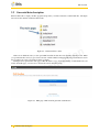
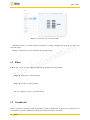
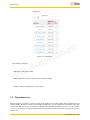
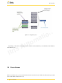
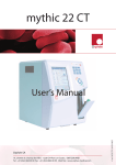
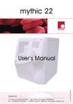
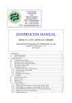
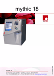
r
t
I
u
A
is
m
to
PLC DocGen
User Manual - 1.0
www.itris-automation.com
©Itris Automation
2008-2015
t
a
n
io
r
t
I
u
A
is
m
to
t
a
n
io
Contents
1 PLC DocGen: Auto generation of documentation and workflow
1.1 General overview . . . . . . . . . . . . . . . . . . . . . . . . . . . . . . . . . . . . . . . . . . . . .
1.2 PLC DocGen features . . . . . . . . . . . . . . . . . . . . . . . . . . . . . . . . . . . . . . . . . . .
1.3 Supported PLC brands . . . . . . . . . . . . . . . . . . . . . . . . . . . . . . . . . . . . . . . . . .
4
4
4
5
2 Presentation of PLC DocGen
2.1 How to generate documentation
2.1.1 Platform as a Service . .
2.1.2 Eclipse-based product .
2.2 Generated data description . . .
.
.
.
.
.
.
.
.
.
.
.
.
.
.
.
.
.
.
.
.
.
.
.
.
.
.
.
.
.
.
.
.
.
.
.
.
.
.
.
.
.
.
.
.
.
.
.
.
.
.
.
.
.
.
.
.
.
.
.
.
.
.
.
.
.
.
.
.
.
.
.
.
.
.
.
.
.
.
.
.
.
.
.
.
.
.
.
.
.
.
.
.
.
.
.
.
.
.
.
.
.
.
.
.
.
.
.
.
.
.
.
.
.
.
.
.
.
.
.
.
.
.
.
.
.
.
.
.
.
.
.
.
.
.
.
.
.
.
.
.
.
.
.
.
.
.
.
.
6
6
6
7
8
3 Data flow
3.1 Filters . . . . . .
3.2 Variables list . . .
3.3 Dependency tree
3.4 Cross reference .
.
.
.
.
.
.
.
.
.
.
.
.
.
.
.
.
.
.
.
.
.
.
.
.
.
.
.
.
.
.
.
.
.
.
.
.
.
.
.
.
.
.
.
.
.
.
.
.
.
.
.
.
.
.
.
.
.
.
.
.
.
.
.
.
.
.
.
.
.
.
.
.
.
.
.
.
.
.
.
.
.
.
.
.
.
.
.
.
.
.
.
.
.
.
.
.
.
.
.
.
.
.
.
.
.
.
.
.
.
.
.
.
.
.
.
.
.
.
.
.
.
.
.
.
.
.
.
.
.
.
.
.
.
.
.
.
.
.
.
.
.
.
.
.
.
.
.
.
9
10
10
11
12
.
.
.
.
.
.
.
.
.
.
.
.
.
.
.
.
.
.
.
.
.
.
.
.
.
.
.
.
.
.
.
.
.
.
.
.
.
.
.
.
.
.
.
.
.
.
.
.
.
.
.
.
.
.
.
.
.
.
.
.
.
.
.
.
.
.
.
.
.
.
.
.
.
.
.
.
.
.
.
.
.
.
.
.
.
.
.
.
.
.
.
.
.
.
.
.
.
.
.
.
.
.
.
.
.
.
.
.
.
.
.
.
.
.
.
.
.
.
.
.
.
.
.
.
15
15
16
16
16
.
.
.
.
.
.
.
.
.
.
.
.
.
.
.
.
.
.
.
.
.
.
.
.
.
.
.
.
u
A
is
4 Control flow
4.1 Filters . . . . . .
4.2 Procedures list . .
4.3 Dependency tree
4.4 Cross reference .
r
t
I
.
.
.
.
.
.
.
.
.
.
.
.
.
.
.
.
.
.
.
.
.
.
.
.
.
.
.
.
.
.
.
.
.
.
.
.
.
.
.
.
.
.
.
.
.
.
.
.
.
.
.
.
.
.
.
.
m
to
.
.
.
.
t
a
n
io
r
t
I
u
A
is
m
to
t
a
n
io
PLC DocGen
Chapter 1
PLC DocGen: Auto generation of
documentation and workflow
1.1 General overview
n
io
PLC DocGen is a reverse-engineering tool that allows you to generate information from an existing PLC source code.
This tool examines and analyzes the PLC structure and functions. The generated information allows you to have a
better understanding of what the PLC code does.
Working on an undocumented program is always a major loss of time:
t
a
1. Commissioning teams miss a clear link between functional specifications and the algorithms in the code, thus
wasting hours during setup and debugging.
m
to
2. Maintenance technicians, working in end-user’s PLC controlled facilities, have to be able to quickly fix erroneous
programs so that production may restart as soon as possible. Thus, they need a clearly documented high-level
model of the behavior of the program.
u
A
is
3. Modernization teams wanting to convert and potentially rewrite an existing legacy program for a more current
hardware shall refer to the original specification and design documentation to make sure that they stay consistent
with the intended behavior of the system.
r
t
I
4. Finally, project managers which have to estimate workloads based on high level specifications may not be able
to fully understand the actual complexity of the job if they don’t have access to a more detailed documentation
closer to the program itself.
This is why it is crucial to use PLC DocGen during the whole life-cycle of your projects. By using PLC DocGen you
get a clearer picture of the whole PLC program. It provides you with all the variables in the program and allows you
to easily maneuver around in the program and get a visual overview of its functioning. PLC DocGen can be used, for
example, for maintenance, code revue, audit, or code debugging.
PLC DocGen is a web-powered tool. It generates html files that you can easily display in your browser (Requires
support for Cross origin requests that is available in some browsers like firefox, IE9, and IE10).
1.2 PLC DocGen features
The main features can be presented as product-oriented and service-oriented features. Product-oriented features are
provided by using the tool directly. Service-oriented features are those, that Itris Automation automation engineers
generate for a specific PLC application.
Product-oriented features are presented as follows:
• Results are generated as a web application that users can display easily in their browsers
• Listing
4
PLC DocGen
• Easy to share results with collaborators
• In compliance with PLC source code whenever the tool is launched
Regarding the service-oriented features, they are for advanced uses of PLC DocGen capabilities such as:
• Listing
• Paper document in A4 or A3
• Different format SVG or PDF
• Possible background animation which results from interaction between the generated SVG graphs (e.g. grafcet,
ladder) and simulation or runtime execution of PLC Code
• In compliance with PLC source code whenever the tool is launched
1.3 Supported PLC brands
The current version of product-oriented PLC DocGen supports the following PLC brands that you can launch directly
from our Platform or from the eclipse-based tool.
• 3S - Codesys (versions 3.1-3.5)
• Mors Technologies - OMEGADCN/TANAGRA (MIP-xx)
• PLCOpen (XML format)
m
to
• Rockwell - RSLogix 5000 (ControlLogix, CompactLogix, . . . )
t
a
n
io
• Rockwell - RSLogix500 (Allen-Bradley SLC500, Micrologix)
u
A
is
• Rockwell - RSLogix5 (Allen-Bradley PLC5)
• Schneider-Electric - XTEL (Telemecanique - PL7-3 serie 7)
• Schneider-Electric - Unity-Pro (Premium, Quantum, M340)
r
t
I
• Schneider-Electric - PL7-Pro (Micro, Premium)
• Schneider-Electric - Orphee (April 2000, 3000, 5000, 7000)
• Schneider-Electric - VPSOFT/EDIDOS (April SMC)
• Siemens - Simatic Step5 (S5-090, S5-100, S5-900)
For service-oriented PLC DocGen, the following PLc Brands are supported. To generate documentation you will need
to contact us to send your PLC application.
• Mitsubishi - GXWorks 2
• Omron - Sysmac Studio v1.0.3 (NJ-series)
• Schneider-Electric - CDE1000 (Merlin-Gerin PB80-PB600)
• Siemens - Simatic Step7 (S7-300, S7-400, C7)
If you need to use the tool for other PLCs, please send us an email at [email protected] by specifying your
PLC brand.
Supported PLC brands
5
PLC DocGen
Chapter 2
Presentation of PLC DocGen
2.1 How to generate documentation
n
io
PLC DocGen can be launched through PLC DocGen Assistant available in our PaaS (Platform as a Service). It can
also be used from our eclipse-based product.
2.1.1
Platform as a Service
u
A
is
m
to
t
a
First of all, users need to be registered to access features and tools provided on Itris’ platform. After that, you will
need to login and then from dashboard page click on the New PLC DocGen button to display the wizard. Follow the
step-by-step instructions as illustrated in the figures below.
r
t
I
Figure 2.1: PLC DocGen Assistant application information
6
PLC DocGen
Figure 2.2: PLC DocGen Assistant file upload
t
a
n
io
Before starting to launch PLC DocGen, ensure that you have sufficient rights to do it, otherwise contact our sales
service by email at [email protected] to order new licenses.
When launching the wizard, results will be displayed in another web interface as depicted in the figure below.
r
t
I
u
A
is
m
to
Figure 2.3: PLC DocGen result page
You can then display the results directly in a web page or download the generated information and display them in
your browser in an off-line mode.
2.1.2
Eclipse-based product
Please contact us for more details about how to use PLC DocGen in eclipse-based product.
How to generate documentation
7
PLC DocGen
2.2 Generated data description
PLC DocGen takes as input your PLC program and provides you with a folder that contains html files. The figure
below shows the structure of PLC DocGen results.
Figure 2.4: Generated folder content
t
a
n
io
There are two different views you can open in PLC DocGen, the data flow view and the control flow view. When
you open the data flow view you get a visual overview of all the variables in the program and you can easily browse in
the program by choosing your preferred settings of display.
The figure below presents the main page of PLC DocGen tool (i.e. by double-clicking on index.html from your
folder). From this page, you can access to the data flow and control flow views.
r
t
I
u
A
is
m
to
Figure 2.5: Main page of PLC DocGen generated documentation
8
Generated data description
PLC DocGen
Chapter 3
Data flow
n
io
The data flow view displays the relationship between variables of a PLC program. By clicking on ”Display Data Flow”
from the main page of PLC DocGen, you will display the data flow view depicted in the figure below. As we can see,
it consists of four parts that are : variable list, cross reference, dependency tree, and filters.
r
t
I
u
A
is
m
to
t
a
Figure 3.1: Data flow view
The variable list is displayed on the left, and when a variable is selected from the list, the variables influencing it
are branching out on the right in the cross reference part and on the middle in the dependency tree part (see the figure
below).
9
PLC DocGen
Figure 3.2: Data flow view of selected variable
n
io
This makes it easier to see which variables are affected if you change something in the program, or to look for an
error in an output.
Each part of the data flow view is described in the following sections.
3.1 Filters
u
A
is
m
to
t
a
In Filters part, you can do some settings for displaying the dependency tree and variables :
r
t
I
• Display the written flow of selected variable
• Display the read flow of selected variable
• Choose to display two levels or one level in the tree
3.2 Variables list
The list of variables of the PLC program is presented as a table (as illustrated by the figure below) in which you can
sort elements in a specific column and search a specific variable by its name or its address.
10
Filters
PLC DocGen
m
to
Figure 3.3: Variable list
u
A
is
The variables are listed by :
r
t
I
t
a
n
io
• Mnemonic : name of the variable
• Memory Reference : memory address of the variable if available
• Nb Dep : Number of dependencies for the variable
3.3 Dependency tree
This area displays the variable you have chosen from the variables list, and the variables that are influenced by this
selected variable. The blue box is the selected variable, the light grey ones are variables that don’t influence any other
variables, the dark grey ones are the variables that influence other variables, and when you mouse over some variables
some boxes become green to show that the green variable is present more than once in the tree. The figure below shows
all these cases.
Dependency tree
11
PLC DocGen
Figure 3.4: Dependency tree
u
A
is
m
to
t
a
n
io
By clicking on one of the boxes in the tree, a new variable is selected and then you see what this variable influences
in the different areas.
r
t
I
3.4 Cross reference
In the cross reference area, you can see the instructions that concern the selected variable. Each instruction is presented
by its location and its related source code.
12
Cross reference
PLC DocGen
m
to
t
a
n
io
Figure 3.5: Cross reference area
r
t
I
u
A
is
In some cases, this area shows also the Memory information if the variable has a data structure type. The figure
below shows the Memory information of a DFB type variable.
Cross reference
13
PLC DocGen
m
to
t
a
Figure 3.6: Cross reference area with memory information
r
t
I
14
u
A
is
Cross reference
n
io
PLC DocGen
Chapter 4
Control flow
The control flow view of a program refers to the order in which the function or procedure calls are executed or evaluated.
By clicking on “Display Control Flow” from the main page of PLC DocGen, you will display the control flow view
depicted in the figure below.
r
t
I
u
A
is
m
to
t
a
n
io
Figure 4.1: Control flow view
The procedures or functions list is displayed on the left, and when a procedure/function is selected from the list,
the procedures/functions influencing it are branching out on the right in the cross reference part and on the middle in
the dependency tree part. Each part of the data flow view is described in the following sections.
4.1 Filters
The filters allow you setting the display of the procedures :
1. When you chose Display tasks only, it allows displaying only the tasks, if not, tasks and other procedures/routines
are displayed.
15
PLC DocGen
2. When you chose Display all nodes, it shows all the direct or indirect linked routines, if not, only the direct linked
routines are displayed.
4.2 Procedures list
The list of procedures of the PLC program are presented as a table as illustrated by the figure below in which you can
sort elements in a specific column and search a specific procedure by its name.
The procedures are listed by :
1. Procedure names
2. Number of dependencies
By clicking on procedure name, the cross reference and dependency tree areas are updated with the new data.
4.3 Dependency tree
Here you can see the procedure you have chosen from the list, and the procedures that are called from this selected
procedure. By clicking on one of the boxes, you see what this procedure calls.
As in Data Flow view, the light grey boxes are procedures that do not call any other procedures, the dark grey boxes
are procedures that call other procedures, and the green boxes are the procedures that are present more than once in the
tree.
4.4 Cross reference
m
to
t
a
n
io
This displays all instructions that concern the selected procedure. Each instruction is preceded by its location and
contains the source code related to the selected procedure.
r
t
I
16
u
A
is
Procedures list
PLC DocGen
m
to
t
a
n
io
For any question or information about Itris Automation products, contact-us by phone at +33(0) 476234320 or
by email at [email protected].
For technical inquiries send an email to [email protected].
r
t
I
u
A
is
17
PLC DocGen
r
t
I
18
u
A
is
m
to
t
a
n
io