1
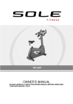
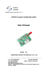
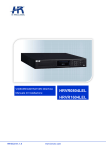
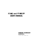
Hi4 Function Manual
Positioner Synchronous
User’s Manual
(v e r s i o n
2.0)
March, 2002
Positioner Synchronous
1. General
1.1 Positioner synchronization function
Positioner synchronization is the function to control a situation where rotational devices
separated physically from robot is synchronously controlled with robot. Using such a function,
robot limitation arising from workspace and work position can be overcome. This enhances
Applicability and workability.
1.2 Positioner
Positioner is normally structured in the shape of turntable shown below. Number of rotational
axis supported by HHI is either one axis or two axes of positioner. HHI provides positioner
function in HR controller as an option.
Second axis
First axis
2 axes positioner
1 axis positioner
1.3 Positioner function Setting
① Robot must have a correct calibration for both tool constant and axis constant.
② Bit constant for positioner must be correctly set up. Bit constant is the constant for
physical rotational direction and angle of positioner per encoder 10,000 bits.
Customer is required to follow instruction of HHI for bit constant value when HHI
supplies positioner.
③ Parameters is setup in a way that delay time of servo motor is matched to delay time
of positioner in order to synchronize and improve synchronous motion between robot
and positioner.
- F1 and F2 in servo loop gain must be identically to all axes with the maximum
value in robot and additional axes.
1/19
Positioner Synchronous
2. Initial state
2.1 Memory format
When controller and manipulator are to be setup at the first, memory format must be carried
out in order to initialize Hyundai robot for use.
14:39:38 *** Initialize *** A:0eS:1
1: System format
2: Selecting type of the robot
4: Setting usage of the robot
5: Positioner group setting
6: Endless axes setting
21: Additional axes setting
22: Servo parameter setting(Add-axis)
Use [Nun]/[Arrow] and press [SET]
>1
Previous Next
In order to display 21/22 menus above, R314 must be entered in Manual or Auto mode.
2.2 Selection of constant file
Select constant file and enter type of robot and number of additional axes and then press
[PF5]“Execute” key. It displays "Make? [Y/N]", you press [SET(YES)] key.
14:39:38 *Robot type selection* A:0 S:1
7: HR006-03 (with R2-cable cover)
The number of additional axes = [2]
Conveyor synchronization = <OFF,ON>
Vibration control mode = <OFF,ON>
Enter number and press [SET]
>[0 - 3]2
Previous Next
2/19
Execute
Positioner Synchronous
2.3 Constant setting for additional axis
It asks "Set constants of additional axes? [Y/N]", Press [SET(YES)] key
14:39:38 *** Constant file *** A:0 S:H1
1: HR120 (Matsushita motor)
2: HR150 (Matsushita motor)
3: HR150S
4: HR100P
5: HR120S
6: HR006-02 (without R2-cable cover)
7: HR006-03 (with R2-cable cover)
8: HR015-01 (Matsushita motor)
9: HR015-02 (Tamagawa motot)
10: HR130-2
11: HR165-2
Set constants of additional axes? [Y/N]
>[0 - 3]2_
Previous Next
14:39:38 ** Additional Ax(1) ** A:0 S:H1
Axis position: BD=[1] DSP=[1] Axis=[4]
Application =<Travelling,Gun,Jig>
Joint pattern =<Nothing,X,Y,Z,Rxyz>
Bit constant
=[
0.00000]
Max RPM
=[1000]
Max Stroke
=[
1]
Enter number and press [SET]
>[1-2]_
Previous Next Complete
① BD=BD440(servo) number, DSP=DSP number in BD440, Axis=axis number
② Application: Select JIG in Application to set an axis for positioner.
③ Joint pattern: In Joint pattern setting axis for positioner. Rxyz shall be selected.
X,Y,Z shall not be selected because Joint pattern of positioner only supports
rotational axes.
④ Bit constant: Reduction ratio shall be considered in order to enter encoder
deg/10000bit for positioner axis.
- (360[degree] x reduction ratio / 8192[bit/rev]) x 10000 (The sign is direction)
⑤ Max RPM: Enter using maximum RPM of motor.
⑥ Max Stroke: Assign movable range of positioner
※ Use [PF4]“Next” key to set not only the first axis but all remaining additional axes.
※ To record setting, [PF5]“Complete” key must be pressed.
.
.
3/19
Positioner Synchronous
2.4 Power off/on
After setting additional axis servo parameters or setting menu and escaping by pressing ESC
key from that setting menu, you must power off and wait 5 seconds and power on again.
2.5 Servo parameter setting
After reboot controller with power on, enter R314 (engineering code) in Manual mode. Press
[PF2]“System” key to enter the system menu.
① Select “3: Machine parameter” -> “12: Servo parameter setting” -> “1: Servo loop
gain” in system menu.
② Position command delay Filters (F1 and F2) must be identically assigned to all axes
with the maximum value in robot and additional axes.
③ Detail tuning; please refer to “Hi4 servo control instruction”.
④ After the completion of setting, turn off the power and power on again.
(Rebooting the system with new setting)
4/19
Positioner Synchronous
3. Robot calibration
3.1 Encoder calibration
“Encoder calibration” is needed after memory format.
Press [PF2]“System” key, and select “3: Machine parameter” -> “5: Setting encoder offset”,
and follow the below steps.
① After motor on, move all each axes of robot to the system or origin position which are
either marked or holes physically. (You can use system position setting pin)
② After moving each axis to system position, press [SET], [REC] key to record the current
robot position
③ For positioner axis, set encoder calibration at the middle position of positioner and mark
the center point with a making pen.
④ After setting all axis including positioner for encoder calibration, press, [PF5]“Complete”
to save the setting data.
Note) The positions of encoder calibration must be remembered because it will be used to
move the robot to the position of encoder recalibration at the of replacing motor in the future.
3.2 Auto constant setting
① Attach ARC torch or any applicable tool to the end-effecter of robot to setup auto tool
constant setting
② If heavy tool is to be attached and can affect robot not able to retain correct system
position due to weight of tool, as low weight as possible setting device should be
considered to be used to set axis constant in auto constant setting and record
“coordinate= base or robot” at fixed point. After this, attach actual tool to be used to
the end-effecter and set “System” -> “3: Machine parameter” -> “1: Tool data” ->
[PF1]“Auto Tool Setting”. By doing this, high accuracy of tool setting is expected.
③ In order to make a program for auto tool setting, orientation of robot in each step shall
have many changes in positioning to record each position steps.
④ When executing auto tool setting, set “Setting=< Constant & Tool, Tool >” in
order to compensate axis constant and hence accuracy will be improved. In other
words, value setup through encoder offset in 3.1 above means error to be
compensated.
※ Refer to Hi4 manual for Auto tool constant setting
5/19
Positioner Synchronous
4. Positioner calibration
4.1 Grouping positioner
① Hi4 controller supports 3 positioner and max 2 axes can be assign per each positioner.
② Positioner group setting is a process to register positioner manipulator and positioner
setup as to JIG axis can be assigned as positioner group.
③ After selecting “5: Initialize” in [PF2]“System” menu, select Sub-menu “5:
Positioner group setting”
14:39:38 *** Initialize *** A:0eS:1
1: System format
2: Selecting type of the robot
4: Setting usage of the robot
5: Positioner group setting
6: Endless axes setting
21: Additional axes setting
22: Servo parameter setting(Add-axis)
Use [Nun]/[Arrow] and press [SET]
>5
Previous Next
In order to display 21/22 menus above, R314 must be entered in Manual/Auto mode.
14:39:38 ** Positioner Group ** A:0 S:H1
Additional Axis
--------------T1 Axis
T2 Axis
T3 Axis
Positioner Group
---------------[0]
[0]
[0]
USAGE) Group number is gradual Increase
Enter number and press [SET]
>[0-1]
Save
▶ Positioner group setting method
Ex.1) In the case of setting two axes positioner and one axis positioner,
(Including additional 3 axes as to JIG)
Additional Axis
--------------T1 Axis
T2 Axis
T3 Axis
Positioner Group
---------------[1]
[1]
[2]
6/19
Positioner Synchronous
T1(First) axis and T2(Second) axis in group1 are assigned as the first positioner group, and
T3 axis will be assigned as 2(Second) positioner group.
Ex.2) In the case of setting one axis positioner and two axes positioner
The case where additional 3 axes are all assigned as to JIG
Additional Axis
--------------T1 Axis
T2 Axis
T3 Axis
Positioner Group
---------------[1]
[2]
[2]
T1 axis alone is assigned as positioner group 1, and T2(First) axis and T3(Second) axis are
assigned as positioner group 2.
Ex.3) In the case of two positioners having one axis
Additional Axis
--------------T1 Axis
T2 Axis
T3 Axis
Positioner Group
---------------[1]
[2]
[0]
T1 axis is assigned as positioner group 1 and T2 axis is assigned as positioner group 2
Ex.4) In the case of setting Jig without positioner function. (Default state)
Additional Axis
--------------T1 Axis
T2 Axis
T3 Axis
Positioner Group
---------------[0]
[0]
[0]
※ Method of assigning positioner group.
① Group shall be sequentially assigned from the axis at low level to the axis at high
level (position)
② Group without synchronization shall be assigned as [0] and assigned after assigning
axis with synchronization.
③ 3 axes shall not be assigned as the same group because the same group in positioner
supports only 2 axes.
④ To record setting, [PF5]“Complete” key must be pressed.
⑤ When you have the situation where you have do group setting again, previous
calibration value of positioner would be lost and do calibration for positioner
once again
7/19
Positioner Synchronous
4.2 Positioner calibration for one axis
Note Robot calibration must be implemented before positioner calibration
① Place sharp pin on the positioner in case of one axis positioner.
② Create a new program. Place tool center point(TCP) of robot to center point of pin in
match and record the first step.
③ Rotate positioner axis at 30 to 90° (Accuracy will be improved as making bigger
angle). Place TCP to the center point of pin and record second step. With the same
method, record step 3. Refer to the below picture.
④ Select “6: Automatic constant setting” in [PF2]“System” menu.
⑤ Select sub-menu “4: Positioner Calibration”.
Point P
CP1
CP2
CP3
Calibration of 1 axis positioner
8/19
Positioner Synchronous
14:39:38*Positioner Calibration*A:0 S:1
Positioner Group No.
Program No.
= [ 1]
= [ 0]
Select and Enter number. Press [SET]
>[1-1]
Execute
⑥ Enter the positioner group to be assigned and enter the program number you created.
By pressing [PF5]“Execute” key, “Save? [Y/N]” will be displayed. Press
[SET(YES)] key if you wish to save. If positioner group is not assigned, following
message will be displayed:
"You must setup the positioner group [ESC]"
14:39:38*Positioner Calibration*A:0 S:1
Positioner Group No.
Program No.
= [ 1]
= [900]
Positioner Group [1] POSE
X=
0.000, Rx= -90.000
Y= 500.000, Ry=
0.000
Z= 300.000, Rz=
90.000
D-H Parameters
DH.a=
0, DH.alpha=
DH.d=
0, DH.theta=
Save? [Y/N]
>[1-1]
0
0
Execute
X/Y/Z : Positioner data from the base coordinate of robot to the base coordinate in
positioner
Rx/Ry/Rz : Angle data through absolute transformation to each axis from the base
coordinate.
D-H Parameters : In case of 2 axes positioner, the DH.a and DH.alpha are calibrated.
DH.a is the distance between two rotation axes and
DH.alpha is the angle[deg] between two rotation axes
9/19
Positioner Synchronous
4.3 Calibration for 2 axes positioner
Note Robot calibration must be implemented before positioner calibration
It is identical to calibration for one axis positioner but 5 points (steps) shall be taught.
① Create a new program. Place sharp pin on the positioner in case of second axis
positioner and record the first step.
② Rotate second axis of positioner at 30 to 90° . Place TCP to the center point of pin
and record second step.
③ Rotate second axis of positioner at 30 to 90° further from second step. Place TCP to
the center point of pin and record third step.
④ Rotate the first axis of positioner at 30 to 90° further from third step. Place TCP to
the center point of pin and record fourth step.
⑤ Rotate the first axis of positioner at 30 to 90° further from forth step. Place TCP to
the center point of pin and record fifth step and end the program
Execute calibration through the same method in 4.2.
⑥
Point P
CP1
5
CP
1
5
CP2
4
CP
2
4
CP3
3
Calibration of 2 axes positioner
10/19
Positioner Synchronous
5. Manual Operation
5.1 AUX LED
When axis operation key is pressed, movement of manipulator will be shown on display in
teaching pendant and as follow;
COORD
AUX LED
JOINT
○ (OFF)
Only robot joint
operation
CART
TOOL
Only robot
Only robot tool-coordinate
Cartesian-coordinate
operation
operation
● (ON)
Only additional axis joint operation
◎ (Blink)
Additional axis operation and follow robot synchronously
(Master=positioner, Slave=robot)
5.2 Non-synchronous operation
[AUX. AXIS] key is used to assign positioner group. When AUX LED is (○ )OFF on
teaching pendant, only robot is operated or moved. This is the same as normal operation
for robot only.
[AUX. AXIS] key is pressed to have AUX LED is (● )ON on teaching pendant, only
additional axis is operated or moved. This is the same as normal operation for additional axis
only.
Only robot operation
Only additional axis operation
11/19
Positioner Synchronous
5.3 Synchronous operation
Positioner group that is completed for positioner calibration can carry out synchronous
operation. Press [AUX. AXIS] key to make AUX LED ◎(blink: On Off repeat) status.
Teaching pendant displays at the top current status information for Master.
14:39:38 *** M A N U A L *** A:0 S:1
T0
M:S1
PNo:010[Ex]__ SNo/F:1/0
Spd:20
Robot:HR006-03, 8axes, 1steps
S1 MOVE P,S=20mm/sec,A=0,H=0
>
Service System Rel.WAIT
Current Master is S1
Cond Set
※ S1 means positioner group 1. Positioner is normally designated as Station(S)
※ If you select positioner which is not calibrated, the following message will be displayed;
"Station # is not executed calibration"
※ Calibration must be carried out in order to use positioner (Station)
※ Robot follows or tracks the movement of positioner in synchronous operation
Note Accurate synchronous movement is expected as calibration for robot and positioner
is performed
Synchronous operation
12/19
Positioner Synchronous
6. Step record & Modify
6.1 Step record according to AUX LED
AUX LED
Interpolation
Master
[REC] at ○ (OFF)
×
PTP
MOVE P
LIN
MOVE L
CIR
MOVE C
[REC] at ● (ON)
×
MOVE P
MOVE L
MOVE C
S1
SMOV S1, L
SMOV S1, L
SMOV S1, C
S2
SMOV S2, L
SMOV S2, L
SMOV S1, C
[REC] at ◎(Blink)
6.2 SMOV
Synchronous step is recorded as SMOV. Step in circular and linear interpolation can be
recorded.. When [REC] is pressed while AUX LED is blinked, SMOV is recorded. Each
command is as following;
14:39:38 *** M A N U A L *** A:0 S:5
T0
M:S1
PNo:010[Ex]__ SNo/F:2/0
Spd:20
Robot:HR006-03, 8axes, 1steps
S1 MOVE P,S=20mm/sec,A=0,H=0
S2 SMOV S1,L,S=20mm/sec,A=0,H=0
>
Service System Rel.WAIT
Cond Set
SMOV= Synchronous MOVE, S1= Master is Positioner_1, .....
6.3 Position modify
-
After selecting step, move the robot and press [Pose MOD] key,
Or after pressing [Quick Open], enter the value and press [PF5]“Save” key to
modify the position.
13/19
Positioner Synchronous
6.4 Change MOVE to SMOV
In case of MOVE without pose variable(P1~P999).
Press [SET] key and place the cursor on MOVE command word. Press [AUX.
AXIS] key to select master and press [REC] key, which will not change recorded
position but change command from MOVE to SMOV. Conditions (Interpolation,
Speed, Accuracy, Tool, ....) except position data are changed in current status.
- Changing from SMOV to MOVE is executed as the same manner above.
② In case of MOVE with Pose variable(P1~P999)
- Similar to the above method but use PF menu in stead of using [REC key to
select either MOVE or SMOV.
①
-
6.5 Example : Teaching Linear interpolation on Positioner
① Assign start and target point on workpiece
S1
S2
S3
② With [AUX. AXIS] key, make “AUX” LED=ON. After moving positioner with JOG
key, make “AUX” LED=OFF with [AUX. AXIS] key and place TCP to the starting
point of job with JOG key. Under this condition, press [REC] key to record “MOVE”
command (If necessary, record as SMOVE command).
③ With [AUX. AXIS] key, select master (“AUX” LED=“Blink”). Select Master=S1 in
the case where positioner for the current job is in Group 1.
Target Point
S1
S3
S2
14/19
Positioner Synchronous
④ When the position of positioner is moved to desired position under the condition that
master is selected, robot maintains it’s position and pose according to the start point
of job on positioner.
Note At the above condition, accuracy error between a point on positioner and TCP is
caused by calibration and cannot be resulted in trajectory accuracy error during
playback. In other words, accuracy error would be hardly resulted through moving
robot to a desired point and recording that position as SMOV even though there is
amount of little accuracy error.
.
S1
S2
S3
⑤ With [AUX. AXIS] key, select “AUX” LED=Off, and move the robot to ‘target’(S2)
with JOG key.
Target Point
S1
S2
S3
⑥ In order to record synchronize step with “SMOV”, press again [AUX. AXIS] to
select “master=S1” and press [REC] key. In this case, linear interpolation is recorded
if “Interpolation=PTP” or “LIN”, circular interpolation is recorded if “CIR”
⑦ Follow next steps following with ③→ ④→ ⑤.
15/19
Positioner Synchronous
S1:Target Point
S2
S1
S3
S2
⑧ Positioner is moved and robot to the workpiece on positioner moves in linear
interpolation as executing recorded program
Positioner synchronization Step playback in linear interpolation
16/19
Positioner Synchronous
NOTE
1. It is not always necessary to following the above method in recording positioner
synchronization step(SMOV). When record “SMOV” step after moving the robot
and positioner respectively to finalize position and pose, robot moves as to
workpiece on positioner in recorded interpolation.
2. In case that two-steps recorded as SMOV are linear interpolation, as MOVE, robot
does cornering motion.
3. Speed of step recorded as SMOV is job speed. Therefore if distance between
workpieces on positioner is very short positioner usually moves at the maximum
speed, even though positioner has many movement, because job speed is at infinite
(∞ ). In this case, set speed unit “SEC” to limit the speed of positioner. In other
words, movement speed between steps is set as time not as speed even though
distance 0 between workpieces on the positioner.
17/19
Positioner Synchronous
7. Running
7.1 Linear interpolation
Move the robot to a point on positioner and record one step, the next step is recorded with
linear interpolation as SMOV, and then running trajectory is linear on positioner.
14:39:38 *** M A N U A L *** A:0 S:5
T0
M:S1
PNo:010[Ex]__ SNo/F:1/0
Spd:20
Robot:H6, 8axes, 1steps
S1 SMOV S1,L,S=20mm/sec,A=0,H=0
S2 SMOV S1,L,S=20mm/sec,A=0,H=0
>
Service System Rel.WAIT
Cond Set
NOTE For continuous step in two straight lines, linear interpolation cornering is
performed
7.2 Circular interpolation
Circular interpolation is executed in the reference of steps on positioner. Circular
interpolation of workpiece is possible in the case of steps recorded in SMOV even
though positioner is moved
14:39:38 *** M A N U A L *** A:0 S:5
T0
M:S1
PNo:010[Ex]__ SNo/F:1/0
Spd:20
Robot:H6, 8axes, 1steps
S1 SMOV S1,L,S=20mm/sec,A=0,H=0
S2 SMOV S1,C,S=20mm/sec,A=0,H=0
S3 SMOV S1,L,S=20mm/sec,A=0,H=0
END
>
Service System Rel.WAIT
Cond Set
7.3 Continuity / Non-continuity in the target
Step in changing Master is non-continuity.
In other words, when the previous step is MOVE and the next step is SMOV, or the previous
step is SMOV and the next step is MOVE, it is operated in non-continuous playback.
18/19