1
Maintenance Guide
July 12, 2007
Document Number: 10256_07
Part Number: 30010
VESDA®
Product Maintenance Guide
Intellectual Property and Copyright
This document includes registered and unregistered trademarks. All trademarks displayed are the trademarks of their respective owners.
Your use of this document does not constitute or create a licence or any other right to use the name and/or trademark and/or label.
This document is subject to copyright owned by Xtralis AG (“Xtralis”). You agree not to copy, communicate to the public, adapt, distribute,
transfer, sell, modify or publish any contents of this document without the express prior written consent of Xtralis.
Disclaimer
The contents of this document is provided on an “as is” basis. No representation or warranty (either express or implied) is made as to the
completeness, accuracy or reliability of the contents of this document. The manufacturer reserves the right to change designs or
specifications without obligation and without further notice. Except as otherwise provided, all warranties, express or implied, including
without limitation any implied warranties of merchantability and fitness for a particular purpose are expressly excluded.
General Warning
This product must only be installed, configured and used strictly in accordance with the General Terms and Conditions, User Manual and
product documents available from Xtralis. All proper health and safety precautions must be taken during the installation, commissioning
and maintenance of the product. The system should not be connected to a power source until all the components have been installed.
Proper safety precautions must be taken during tests and maintenance of the products when these are still connected to the power source.
Failure to do so or tampering with the electronics inside the products can result in an electric shock causing injury or death and may cause
equipment damage. Xtralis is not responsible and cannot be held accountable for any liability that may arise due to improper use of the
equipment and/or failure to take proper precautions. Only persons trained through an Xtralis accredited training course can install, test and
maintain the system.
Liability
You agree to install, configure and use the products strictly in accordance with the User Manual and product documents available from
Xtralis.
Xtralis is not liable to you or any other person for incidental, indirect, or consequential loss, expense or damages of any kind including
without limitation, loss of business, loss of profits or loss of data arising out of your use of the products. Without limiting this general
disclaimer the following specific warnings and disclaimers also apply:
Fitness for Purpose
You agree that you have been provided with a reasonable opportunity to appraise the products and have made your own independent
assessment of the fitness or suitability of the products for your purpose. You acknowledge that you have not relied on any oral or written
information, representation or advice given by or on behalf of Xtralis or its representatives.
Total Liability
To the fullest extent permitted by law that any limitation or exclusion cannot apply, the total liability of Xtralis in relation to the products is
limited to:
(i) in the case of services, the cost of having the services supplied again; or
(ii) in the case of goods, the lowest cost of replacing the goods, acquiring equivalent goods or having the goods repaired.
Indemnification
You agree to fully indemnify and hold Xtralis harmless for any claim, cost, demand or damage (including legal costs on a full indemnity
basis) incurred or which may be incurred arising from your use of the products.
Miscellaneous
If any provision outlined above is found to be invalid or unenforceable by a court of law, such invalidity or unenforceability will not affect the
remainder which will continue in full force and effect. All rights not expressly granted are reserved.
Document Conventions
The following typographic conventions are used in this document.
Convention
Description
Bold
Used to denote: emphasis
Used for names of menus, menu options, toolbar buttons
Italics
Used to denote: references to other parts of this document or
other documents. Used for the result of an action.
The following icons are used in this document
Convention
Description
Caution: This icon is used to indicate that there is a danger to
equipment. The danger could be loss of data, physical damage,
or permanent corruption of configuration details.
i
VESDA®
Product Maintenance Guide
Warning: This icon is used to indicate that there is a danger of
electric shock. This may lead to death or permanent injury.
Warning: This icon is used to indicate that there is a danger of
inhaling dangerous substances. This may lead to death or
permanent injury.
Contact Us
The Americas
+1 781 740 2223
Asia
+852 2297 2438
Australia and New Zealand
+61 3 9936 7000
Continental Europe
+41 55 285 99 99
UK and the Middle East
+44 1442 242 330
www.xtralis.com
Codes and Standards Information for Air Sampling Smoke Detection
We strongly recommend that this document is read in conjunction with the appropriate local codes and standards for smoke detection and
electrical connections. This document contains generic product information and some sections may not comply with all local codes and
standards. In these cases, the local codes and standards must take precedence. The information below was correct at time of printing but
may now be out of date, check with your local codes, standards and listings for the current restrictions.
FCC Compliance Statement
This equipment has been tested and found to comply with the limits for a Class B digital device, pursuant to part 15 of the FCC Rules.
These limits are designed to provide reasonable protection against harmful interference in a residential installation. This equipment
generates, uses and can radiate radio frequency energy and, if not installed and used in accordance with the instruction, may cause
harmful interference to radio communications. However, there is no guarantee that interference will not occur in a particular installation. If
this equipment does cause harmful interference to radio or television reception, the user is encouraged to try to correct the interference by
one or more of the following measures; re-orientate or relocate the receiving antenna, increase the separation between the equipment and
receiver, connect the equipment to a power outlet which is on a different power circuit to the receiver or consult the dealer or an
experienced radio/television technician for help.
FDA
This VESDA product incorporates a laser device and is classified as a Class 1 laser product that complies with FDA regulations 21 CFR
1040.10. The laser is housed in a sealed detector chamber and contains no serviceable parts. The laser emits invisible light and can be
hazardous if viewed with the naked eye. Under no circumstances should the detector chamber be opened.
FM
3611 Hazardous Approval Warning: Exposure to some chemicals may degrade the sealing of relays used on the detector. Relays used on
the detector are marked “TX2-5V”, “G6S-2-5V” or “EC2-5NU”.
VESDA detectors must not be connected or disconnected to a PC while the equipment is powered in an FM Division 2 hazardous
(classified) location (defined by FM 3611).
FM Approved Applications
The product must be powered from VPS-100US-120, VPS-100US-220 or VPS-220 only.
ONORM F3014
ONORM F3014, transport times for all tubes (including capillaries) must not exceed 60 seconds from any hole. This means that the predesigned pipe networks that include capillaries cannot be used.
AS1603.8
The performance of this product is dependent upon the configuration of the pipe network. Any extensions or modifications to the pipe
network may cause the product to stop working correctly. You must check that ASPIRE2 approves alterations before making any changes.
ASPIRE2 is available from your VESDA ASD distributor.
AS1851.1 2005
Maintenance Standards. Wherever this document and the AS1851.1 differ, AS1851.1 should be followed in preference to this document.
European Installations
The product must use a power supply conforming to EN54: Part 4.
Document Number: 10256_07
Part Number: 30010
ii
VESDA®
Product Maintenance Guide
iii
Product Maintenance Guide
iv
VESDA®
®
VESDA
Maintenance Guide
1. Introduction .................................................................................................................................... 1
1.1 Scope ................................................................................................................................... 1
1.2 Maintenance guide brief outline ........................................................................................... 1
1.3 Maintenance overview - Who & When? ............................................................................... 1
1.4 Important pre-maintenance preparations ............................................................................. 2
1.5 Maintenance schedule summary ......................................................................................... 2
2. Detector maintenance.................................................................................................................... 2
2.1 Maintenance considerations ................................................................................................ 2
2.2 Equipment required.............................................................................................................. 3
2.3 Determining a maintenance schedule.................................................................................. 3
2.4 Maintenance procedures...................................................................................................... 4
2.5 Unscheduled maintenance................................................................................................... 5
2.6 Checking airflow................................................................................................................... 6
2.7 Checking the filter ................................................................................................................ 6
3. Power supply maintenance ........................................................................................................... 7
4. Sample Pipe Network maintenance.............................................................................................. 7
4.1 Important pre-maintenance preparations ............................................................................. 7
4.2 Cleaning sample pipes......................................................................................................... 7
4.3 Cleaning sample holes......................................................................................................... 8
4.4 Cleaning capillary tubes ....................................................................................................... 9
5. Post-maintenance testing.............................................................................................................. 9
6. Annual testing .............................................................................................................................. 10
6.1 Detector tests ..................................................................................................................... 10
6.2 System fire panel notification tests..................................................................................... 11
7. Replacing detector components................................................................................................. 11
7.1 Replacing LaserPLUS and LaserSCANNER filter cartridges............................................. 11
7.2 Replacing the LaserCOMPACT filter cartridge .................................................................. 12
7.3 Replacing the LaserFOCUS filter cartridge........................................................................ 13
7.4 Replacing LaserPLUS and LaserSCANNER chassis ........................................................ 14
7.5 Replacing LaserPLUS and LaserSCANNER aspirators .................................................... 17
7.6 Replacing the LaserCOMPACT aspirator .......................................................................... 19
7.7 Replacing the LaserFOCUS aspirator................................................................................ 20
7.8 Replacing LaserPLUS and LaserSCANNER termination cards......................................... 21
7.9 Replacing the LaserCOMPACT termination card .............................................................. 22
7.10 Replacing LaserPLUS and LaserSCANNER detector modules....................................... 23
7.11 Inspecting and cleaning LaserSCANNER valves............................................................. 23
Appendix A: Laser Products Parts List........................................................................................... 25
Appendix B: Recommended frequencies for general maintenance
and filter cartridge replacement ........................................................................................................ 27
Appendix C: Example Of A Typical Maintenance Log ................................................................... 29
Document No. 10256_07
Maintenance Guide
Document No. 10256_07
®
VESDA
®
VESDA
1
Maintenance Guide
Introduction
1.1
Scope
This Maintenance Guide provides essential information for service personnel maintaining
VESDA laser detector systems. It includes suggestions for a maintenance schedule and
instructions on servicing the different VESDA detector components.
Knowledge about local fire regulations, electrical codes and standards is assumed. Anyone
responsible for maintenance should possess this knowledge.
Important Note: Xtralis strongly recommends that all persons who install, commission, service
and/or maintain VESDA systems attend the VESDA accreditation training. Please contact your
local Xtralis office for more information.
1.2
Maintenance guide brief outline
The information presented in this Maintenance Guide is arranged into the following sections:
•
•
•
•
•
•
•
•
•
Section 2 - describes how to determine an appropriate maintenance schedule and
maintenance procedures for VESDA detectors.
Section 3 - describes how to maintain the power supply.
Section 4 - describes how to maintain the sample pipe network.
Section 5 - provides information on post-maintenance testing.
Section 6 - provides information on annual testing.
Section 7 - describes the procedures for replacing parts on the range of VESDA detectors
Appendix A: provides a list of part numbers.
Appendix B: provides application specific information on determining an appropriate
maintenance schedule.
Appendix C: provides a sample maintenance log, which should be completed as part of
each maintenance visit.
1.3
Maintenance overview - Who & When?
To maintain the VESDA laser detector system at its peak performance level, the suggested
maintenance schedule should be followed. Maintenance can be conducted by the original
installer, a VESDA distributor or a service contractor. The optimum operation of a VESDA laser
detector system requires that the equipment is supported by a well designed and maintained
sample pipe network. The site conditions and the local codes & standards may require more
regular maintenance than that recommended by Xtralis.
Maintenance frequency must be increased in industrial applications such as coal-fired power
stations, factories, distribution facilities and warehousing with high vehicular traffic loads since
these applications commonly have high levels of background pollution.
Note:
Xtralis have adopted the fire industry term 'Disable' for the VLF and all future
products. The VLP, VLS and VLC continue to use the term 'Isolate'. Both terms are
used throughout this document and have the same meaning.
Note:
Xtralis have adopted the fire industry term 'Address' instead of the formerly used
term ‘Zone’ for the VLF and all future products. The VLP, VLS and VLC continue to
use the term 'Zone'. Both terms are used throughout this document and have the
same meaning.
Document No. 10256_07
1
®
VESDA
Maintenance Guide
1.4
Important pre-maintenance preparations
All maintenance procedures require the VESDA system to be isolated during maintenance and
testing. Failure to isolate the system, may lead to unwanted alarms and initiation of fire response
systems. When a VESDA system has to be isolated, alarms will be displayed but no relays will
be tripped. Prior to isolating a VESDA system for maintenance, you must do the following:
1.
2.
Inform the appropriate supervising authority about the risk associated with isolating a
VESDA Address.
Ensure that any ancillary devices, dependent on the detector, are appropriately isolated.
When a VESDA detector is isolated, a fault is signalled at the monitoring system. This is
acknowledged either by wiring the isolate relay in series with the fault relay (VLP and VLS)
or by configuring the fault relay (fault number 3) to trigger an isolate.
1.5
Maintenance schedule summary
Table 1 contains a summary of the suggested maintenance schedule.
Table 1: VESDA maintenance schedule summary.
Monthly
Six Monthly
Every Visit
Check Detector & Filter
See Recommended VESDA Maintenance Period & Filter Cartridge
Replacement Frequency Appendix B:.
Check Power Supply
9
Inspect Pipe Network
9
Check Air flow (per pipe)
9
Perform System Integrity Smoke
Test
9
Clean Sampling Points
9
Flush Pipe Network
9
Note:
2
Annual
Every Two
Years
Maintenance Task
The above table only applies to clean environments.
If local codes and standards for the site require more frequent maintenance, their
guidelines must override those suggested in this Maintenance Guide.
Maintenance schedules may also vary according to operating conditions.
Sample pipe flushing and the cleaning of sample holes should be conducted as
frequently as required by the detector type and environment.
Detector maintenance
2.1
Maintenance considerations
Before beginning system maintenance, the important considerations are as follows:
•
•
•
2
What will the maintenance schedule be?
What maintenance procedures will be required?
What unscheduled maintenance needs may arise?
Document No. 10256_07
®
VESDA
2.2
Maintenance Guide
Equipment required
In order to properly maintain the VESDA system, you will require the following equipment:
•
•
•
•
•
•
•
•
•
2.3
Phillips head screwdriver "1" (length 90 mm minimum) - for filter replacement.
Phillips head screwdriver "2" - for removing all detector covers.
PC with VSC and a High Level Interface (HLI), HLI model number VHX-0200 or VHX-0210.
Xtralis recommends the use of VSC and a HLI. However, a hand-held programmer could
also be used for this purpose.
Vacuum cleaner.
Air compressor.
Spare parts (refer to Appendix A: Laser Products Parts List on page 25).
Records for commissioning and a maintenance history.
Maintenance logs or record sheets.
The original ASPIRE2 design file and commissioning history (optional).
Determining a maintenance schedule
The background smoke readings, recorded in the VESDA detector event log, provide a
representative value for the protected environment. Use of these logs allows the recommended
filter replacement frequency to be calculated, a maintenance program developed and a
maintenance schedule determined.
VSC can be used to access the event log to determine the average background smoke level.
Average smoke levels over a 15-minute period (minimum), where conditions should reflect the
typical operating area, provide enough data to determine the environment type. For clean
environments, the significant smoke change will need to be set to 0.005%obs/m (0.0015%obs/ ft)
for the test period. Remember to return this setting to its original value, once the test is
completed.
Important Note: The following steps do not represent a complete list of instructions. You must
also refer to the sections, of this manual, specific to the various types of VESDA detector.
To determine an appropriate maintenance schedule, follow the instructions listed below:
1.
2.
3.
Ensure that detectors are isolated from the monitoring panel and suppression systems.
Notify the relevant authorities about the work to be performed and the risks associated with
isolating a VESDA address.
If a filter fault is displayed, the current filter is older than the recommended filter
replacement frequency. Replace the filter, according to the detector's guidelines, making
sure that you write the date of replacement on the label and take measures to order stock
(VSP-005) for the next replacement date. For detector specific filter replacement
instructions, refer to Replacing LaserPLUS and LaserSCANNER filter cartridges on
page 11, Replacing the LaserCOMPACT filter cartridge on page 12 and Replacing the
LaserFOCUS filter cartridge on page 13. The color codes for the dates of filter manufacture
are given in Table 2.
Table 2: Color codes for filter date of manufacture.
Document No. 10256_07
Color
Date
Yellow
July 2006
Green
July 2004
Orange
July 2000
Blue
July 1997
3
Maintenance Guide
4.
5.
6.
7.
8.
9.
10.
11.
12.
13.
2.4
®
VESDA
Check for and record any detector faults.
Prior to downloading the smoke event log, use VSC to check the significant smoke change
setting. If it is still at the factory default value of 0.02%obs/m (0.0063%obs/ft) or some other
value, record it then change it to 0.005%obs/m (0.0015%obs/ft).
Run the detector for 15 minutes minimum (longer is recommended in very stable or clean
environments).
Download and save the event log for comparison of smoke readings during normal
operation.
Determine the detector's background smoke level and estimate the average recorded level,
for typical operation, during the test period.
Compare the results with Appendix B: Recommended frequencies for general maintenance
and filter cartridge replacement on page 27 to determine your VESDA system's
environment class.
Based on your system's environment class, establish an appropriate detector and filter
maintenance schedule.
Using VSC, set the filter service timer to the value, in days, given in Appendix B:
Recommended frequencies for general maintenance and filter cartridge replacement on
page 27.
Using VSC, return the significant smoke change setting to its original value.
Proceed to the next section or, if your system is showing no faults, return it to its normal
operating mode.
Maintenance procedures
This section provides instructions for the regular maintenance of detectors. If you need to
address faults, refer to the Troubleshooting Guide for a list of VESDAnet faults. Should you need
to address the 10 instant fault finder faults, on the VESDA LaserFOCUS (VLF) detector, refer to
its Product Guide.
Further information on maintenance, part replacement and recommended filter cartridge
replacement frequency are provided throughout the remainder of this document.
Important Note: Xtralis recommends that you record all work you perform in a maintenance log
such as that in Appendix C: Example Of A Typical Maintenance Log on page 29.
If you do not need to determine a maintenance schedule, continue with the instructions listed
below:
1.
2.
3.
4.
5.
6.
7.
8.
9.
4
Ensure that the detectors are isolated from the monitoring panel and suppression systems.
Notify the relevant authorities about the work to be performed and the risks associated with
isolating a VESDA address.
Check for and record any detector faults.
If a filter fault is displayed, the current filter is older than the recommended filter
replacement frequency. Replace the filter, according to the detector's guidelines, making
sure that you write the date of replacement on the label and take measures to order stock
(VSP-005) for the next replacement date. For detector specific filter replacement
instructions, refer to Replacing LaserPLUS and LaserSCANNER filter cartridges on
page 11, Replacing the LaserCOMPACT filter cartridge on page 12 and Replacing the
LaserFOCUS filter cartridge on page 13. The color codes for the dates of filter manufacture
are given in Table 2 above.
Download and save the event log for comparison of smoke readings during normal
operation.
Record the current airflow (% and raw values) for before and after comparison.
Disconnect power to the VESDA detector.
Remove dust from around the pipe inlets.
Disconnect all pipes from the detector inlet(s) and exhausts then cover them to ensure that
no unwanted material can enter the detector.
Document No. 10256_07
®
VESDA
Maintenance Guide
10. Optional - proceed with this step if there is a low flow fault, a noisy aspirator, excessive or
noticeable dust around the exhaust. Remove the detector aspirator (refer to Replacing
LaserPLUS and LaserSCANNER aspirators on page 17 or Replacing the LaserCOMPACT
aspirator on page 19) and blow it out with compressed air. Make sure that it is cleaned well
away from the detector. The aspirator can collect a significant amount of material in dusty
environments, cleaning with compressed air (400 KPa) may produce a large quantity of
dust.
11. Remove the filter and clean any visible dust around it.
12. Reconnect all pipes.
13. Re-assemble the detector aspirator and filter.
14. Turn the power supply back on.
15. Allow the VESDA detector to operate for 15 minutes (still in isolate/disable mode).
16. View any faults present and take the appropriate action to fix them.
17. After allowing the detector to operate in a stable and correct state for 15 minutes, review the
event log to monitor the background smoke level.
18. Check this value against the Environment Class (Appendix B: Recommended frequencies
for general maintenance and filter cartridge replacement on page 27) to determine the next
scheduled maintenance period.
19. Set the filter timer to reflect the correct environment.
20. Compare the background smoke level with that recorded during previous maintenance
visits. While the background smoke level should be the same, it may be different if your
environment has changed. If a difference in background smoke level cannot be explained
by a change in your environment, you should do one or all of the following: clean the
detector, clean the sample pipe network and/or change the filter. If you do any or all of
these, you should re-check the background smoke level before proceeding.
21. Compare the before maintenance and after maintenance flow rates. Ideally, the flow rate
should be close to 100% for each used pipe. If this is not the case, check the sample pipe
network for loose connections or obstructions.
22. If necessary, clean the detector and sample pipe network (refer to Sample Pipe Network
maintenance on page 7).
23. If the sample pipe network is OK, review the event log. If the event log does not show any
unexpected flow faults, normalize the raw airflow.
24. Once the detector and sample pipe network have been serviced, cleaned, tested (for testing
instructions, refer to Post-maintenance testing on page 9), and are operating fault-free,
return the system to its normal operating mode.
2.5
Unscheduled maintenance
There will be occasions where unscheduled detector maintenance is required. Such instances
are often the result of fault conditions. Faults can range from minor, "minor low airflow pipe 2", to
urgent and must be dealt with by trained and qualified personnel. A full investigation of any
reported fault must be conducted, taking into account all possible causes of the fault.
For further information, refer to the VESDA Troubleshooting Guide in the System Design Manual
or visit www.xtralis.com/vesda.
Document No. 10256_07
5
®
VESDA
Maintenance Guide
2.6
Checking airflow
Every time you visit a site, it is recommended that you check and record the airflow in each
sample pipe. The current percentage airflow readings indicate any changes in airflow percentage
since the last airflow normalization. These readings may not indicate the absolute increase or
decrease in airflow through the sample pipe network. Airflow changes could be a result of one of
the following:
•
•
•
•
•
Blockages - within sample pipes, at sample holes or in capillary tubes.
Leaks - in sample pipes or at pipe junctions.
Airflow changes - introduced by building ventilation systems, changes in sample pipe
network layout or pipe length etc.
Aspirator degradation.
Detector contamination.
Check the airflow in each sample pipe by following the instructions below:
1.
2.
3.
Check the recent airflow data recorded in the event log. Look for flow faults that endured for
a considerable period of time or frequent normalizations. If there are repeated flow faults or
detector normalizations in the event log, detector and system cleaning may be required.
Fix any problems from the list above, blockages for example. If there are no obvious
problems, use VSC to check the raw airflow through the detector (VLP, VLS and VLC only).
Compare the raw airflow against previous historical data.
Note:
Progressive decreases in the raw airflow readings may indicate a blockage
developing inside the sample pipe network. An unexpected reduction of airflow over
an extended period of time may indicate that pipe cleaning is urgently required.
Record separate raw airflow results for each sample pipe. When comparing
successive raw airflows, ensure that the values compared are for the same sample
pipes and check that the pipe network has not changed recently.
The VLF measures flow in liters per minute, not raw airflow, unless it has a
VESDAnet card in which case it displays a value that when divided by 100 equates
to an airflow in liters per minute.
Refer to the VSC online help for information on how to obtain current raw airflow data for VLP,
VLS and VLC products.
2.7
Checking the filter
When checking the filter, compare the date of installation on the filter label with the
recommendations in Appendix B: Recommended frequencies for general maintenance and filter
cartridge replacement on page 27. If in doubt, replace the filter with a new one and record the
date on its label.
Important Note: Serious smoke events, such as those indicated by Fire level alarms, can also
affect the life expectancy of filter cartridges. Filter cartridges should be replaced after all actual
fire events.
6
Document No. 10256_07
®
VESDA
3
Maintenance Guide
Power supply maintenance
The VESDA laser detector system power supply should be checked, at least, every six months
or as required by local codes and standards. VESDA laser products are designed to operate
between 18 VDC and 30 VDC. We recommend, as an absolute minimum, that you check the
following:
•
•
•
•
4
Input voltage - from DC power supply to detector.
Output voltage - from detector to other VESDA devices.
Backup battery voltage - 24 VDC.
Charging backup battery voltage - typically 27.6 VDC.
Sample Pipe Network maintenance
4.1
Important pre-maintenance preparations
Every six months, you should perform a visual check for any damaged sample pipes or pipe
junctions and do repairs as necessary. If damaged or blocked sample pipes go unrepaired,
detector flow faults can occur.
Prior to isolating a VESDA system for maintenance, the following important steps must be taken:
1.
2.
Inform appropriate supervising authorities about the risk associated with isolating a VESDA
Address.
Ensure that any ancillary devices, dependent on the detector, are appropriately isolated.
Warning:
4.2
Inhalation of dust is hazardous to health. Dust build up may contain
potentially dangerous toxic materials. All cleaning processes must be
suitably modified in such instances to negate the risk from toxic
materials. Adequate precautions must be taken to comply with local
health and safety regulations.
Cleaning sample pipes
For environment classes 1 & 2, it is recommended that the sample pipe network be checked
every two years. However, your system's environment will affect this so refer to Appendix B:
Recommended frequencies for general maintenance and filter cartridge replacement on
page 27. The scheduled period should be reduced to suit harsh site environments.
Note:
Local code guidelines may require more frequent inspections for all classes.
Where possible, sample pipes and their connections should be checked to ensure that the pipe
runs are intact and that the network is free of dirt and dust.
Follow the instructions below to clean your sample pipe network:
1.
2.
3.
4.
5.
6.
7.
8.
Ensure that detectors are isolated from the monitoring panel and fire suppression systems.
Notify the relevant authorities that the work is being performed.
Check and record the current airflow for before and after comparison.
Disconnect the detector power supply.
Remove all pipes from the detector inlet(s) and exhausts then cover them to ensure that no
further dust can enter the detector.
Ensure that end caps are set firmly in place.
Connect a vacuum cleaner to the detector end of each pipe in turn. When turned on, it will
extract dust and contaminants that have built up inside the pipes.
Alternatively, introduce compressed air (400 KPa for 2 minutes) at the detector end of each
pipe in turn to blow dust and contaminants out through the sample holes.
Document No. 10256_07
7
Maintenance Guide
®
VESDA
9.
Take precautions to ensure that dust is not blown into undesired areas. Ensure that end
caps are still set firmly in place.
10. Compare the before and after flow rates. Ideally, the flow should be close to 100% for each
used pipe. If this is not the case, the capillaries and detector may need closer inspection. If
the sample pipe network appears to be OK, continue with the remainder of this section to
determine the cause of the reduced airflow.
11. Once the system has been serviced, cleaned, tested and is operating fault-free, return it to
its normal operating mode.
Note:
Sites with dirty environments, which require very regular sample and exhaust pipe
cleaning, should consider installing automated equipment to assist with regular
cleaning schedules.
For more information, refer to Xtralis's Application Note - VESDA Air Sampling for Ducts
available on our website at www.xtralis.com.
Note:
4.3
For in-duct sampling remove the pipe(s) from the duct and follow the cleaning
process. Once cleaning is complete, return the pipe(s) to their original angle
(usually 45° to the airflow).
Cleaning sample holes
We suggest that sample holes are cleaned, at least, once every two years. This is a
recommended interval for environment classes 1 & 2 but your environment will have an effect on
how often sample holes require cleaning, refer to Appendix B: Recommended frequencies for
general maintenance and filter cartridge replacement on page 27. The scheduled period should
be reduced to suit harsh site environments. Cleaning is required to remove any dust build up and
to ensure that the in-pipe sample holes are not blocked.
To clean in-pipe sample holes, follow the instructions below:
1.
2.
3.
4.
5.
Ensure that detectors are isolated from the monitoring panel and fire suppression systems.
Notify the relevant authorities that work is being performed.
Check and record the current airflow for before and after comparison.
Disconnect the detector power supply.
Remove all pipes from the detector inlet(s) and exhausts then cover them to ensure that no
further dust can enter the detector.
6. Connect a vacuum cleaner to each in-pipe sampling hole in turn to extract dust and
contaminants that have built up.
7. Alternatively, introduce compressed air (400 KPa for 2 minutes) at the detector end of the
pipe to blow dust and contaminants out of the sample holes. Take precautions to ensure
that dust is not blown into undesired areas.
8. Visually check that the in-pipe sampling holes have a clear air path.
9. Compare the before and after flow rates. Ideally, the flow should be close to 100% for each
used pipe. If this is not the case, the capillaries and detector may need closer inspection.
10. If the sample pipe network appears to be OK, continue with the remainder of this section to
determine the cause of reduced airflow.
11. Once the system has been serviced, cleaned, tested and is operating fault-free, return it to
its normal operating mode.
Note:
8
Sites with dirty environments, which require very regular sample pipe and sample
hole cleaning, should consider installing automated equipment to assist with regular
cleaning schedules.
Document No. 10256_07
®
VESDA
Maintenance Guide
4.4
Cleaning capillary tubes
We suggest that capillary tubes be cleaned, at least, once every two years. This is a
recommended interval for environment classes 1 & 2 but your system environment will have an
effect on how often capillary tubes require cleaning, refer to Appendix B: Recommended
frequencies for general maintenance and filter cartridge replacement on page 27. The scheduled
period should be reduced to suit harsh site environments. Cleaning may be required to remove
any dust build up and to ensure that the capillary tubes are not blocked.
To clean capillary tubes, follow the instructions below:
1.
2.
3.
4.
5.
6.
7.
8.
9.
10.
11.
12.
13.
Ensure that detectors are isolated from the monitoring panel and fire suppression systems.
Notify the relevant authorities that work is being performed.
Check and record the current airflow for before and after comparison.
Disconnect the detector power supply.
Remove all pipes from the detector inlet(s) and exhausts then cover them to ensure that no
further dust can enter the detector.
Remove the capillary tubes from the sample pipe and unscrew the sampling end pieces, if
applicable.
Clean out the capillary tubes and sampling end pieces with a vacuum cleaner or
compressed air source.
Visually check that each part has a clear air path.
Reassemble the sampling end pieces, if applicable, and connect them to the capillary
tubes.
Reconnect the capillary tubes to the sample pipe network, ensuring that there are no kinks.
If the sample pipe network is also to be flushed, do not reconnect the capillary tubes until
this has occurred.
Compare the before and after flow rates. Ideally, the flow should be close to 100% for each
used pipe. If this is not the case, the pipe network and detector may need closer inspection.
If the sample pipe network appears to be OK, continue with any remaining maintenance
tasks to determine the cause of reduced airflow.
Once the system has been serviced, cleaned, tested and is operating fault-free, return it to
its normal operating mode.
Note:
5
Sites with dirty environments, which require very regular capillary tube cleaning,
should consider installing automated equipment to assist with regular cleaning
schedules.
Post-maintenance testing
Post-maintenance tests should be performed, after a maintenance visit, to determine whether
the system is functional. Take the appropriate measures to ensure that this testing does not
result in unwanted intervention from response systems, for example, suppression.
Consult your local code guidelines to establish the following:
•
•
The minimum testing required per sample pipe.
The appropriate alarm threshold per sample pipe.
Here are some examples of possible tests:
•
•
•
•
You could create a fault to ensure that it is registered by the detector and monitoring system
(for example, remove a pipe to create a high airflow fault).
You could inject smoke into the last sample hole to see whether it is detected.
Likewise, you could inject smoke into critical sample holes to see whether it is detected.
More specifically, you could inject smoke into sample holes only in sections of the pipe
network where maintenance has been performed. to check the effectiveness of that
maintenance.
Document No. 10256_07
9
®
VESDA
Maintenance Guide
With all smoke injections, you need to record transport time, ensure that a significant amount of
smoke is registered and that alarm(s) are generated. The alarm thresholds and amount of smoke
injected may have an impact on the results. You should compare times with the ASPIRE2 design
files, commissioning tests and service history.
Note:
Transport time is the time taken (in seconds) for the smoke to travel to the detector.
Typically, allowing for small variations, the result should be approximately the same
as the ASPIRE2 calculations.
In the event that there is a wide variation between the ASPIRE2 results and the actual smoke
test results, you must investigate the following:
1.
2.
3.
4.
Check that the sample pipe network matches your ASPIRE2 design.
Check that the aspirator speed matches your ASPIRE2 design (VLP and VLS only).
Check for any preset alarm delays.
Check the sample pipe network for leaks and blockages.
Note:
•
•
•
•
•
Read and carefully follow all instructions on the canned smoke product.
Take all necessary health and safety precautions.
Avoid inhaling the fumes.
Avoid spraying the canned smoke directly into the detector or the pipe inlets.
Avoid prolonged bursts - use in short bursts of less than 2 seconds.
Note:
6
Xtralis does not recommend the use of canned smoke to perform post-maintenance
tests. However, if you do use canned smoke, you should ensure that you do the
following:
Prolonged use of canned smoke can damage plastic components and the detector
itself, thereby, invalidating the detector's warranty.
Annual testing
Local code guidelines may state that system and detector tests be conducted on a regular basis.
Xtralis recommends that such tests be conducted, at least, annually. However, there are some
environments in which it is necessary to conduct maintenance and testing more frequently, refer
to Appendix B: Recommended frequencies for general maintenance and filter cartridge
replacement on page 27.
Note:
A sample maintenance and testing log is provided in Appendix C: Example Of A
Typical Maintenance Log on page 29.
Important Note: Xtralis strongly recommends that all persons who install, commission, service
and maintain VESDA systems attend the VESDA accreditation training. Please contact your local
Xtralis office for more information.
6.1
Detector tests
Check the following items to ensure that performance is still satisfactory:
1.
2.
3.
4.
5.
10
Recorded faults - If any faults are present, record and rectify them before beginning any
maintenance.
Power supply - Ensure that the input voltage is within the operating requirements.
Backup battery (if installed) - Check that the batteries are fully charged and the charging
voltage is functioning correctly.
Airflow - Check the airflow for each sample pipe in use. Compare to previous site visit data
to ensure that there is no degradation in performance due to pipe blockages, leaks, breaks
or contamination.
Smoke test - Inject an appropriate level of smoke into the required sampling holes.
Document No. 10256_07
®
VESDA
Maintenance Guide
6.
Record Transport Time - This figure should be consistent with your previous maintenance
visit or your original commissioning documentation. Refer to your local standards for
allowable variations.
7. Local detector display - Ensure that the detector's front panel display responds
appropriately to any faults and smoke levels, within the time specified in your local code
guidelines.
8. Relay performance - Ensure that the detector's fire and fault relays are functioning correctly.
9. Remote detector display - Ensure that any associated remote detector displays (if installed)
respond appropriately to any faults and smoke levels, within the time specified in your local
code guidelines.
10. Record results - Xtralis recommends that you photocopy the sample maintenance log in
Appendix C: Example Of A Typical Maintenance Log on page 29 and record all results on
the copy. Store the log in an appropriate known location on-site.
11. Compare all results to previous recorded tests - Ensure that there is no degradation in
performance. If a noticeable change is observed, maintenance of the detector and/or
sample pipe network may be necessary.
12. Schedule next visit - Determine the appropriate time for the next site visit by referring to
Appendix B: Recommended frequencies for general maintenance and filter cartridge
replacement on page 27.
6.2
System fire panel notification tests
Your detector alarm and fault tests should register on the monitoring system, within a time frame
consistent with local standards. System notification results should be recorded in the detector
maintenance log.
7
Replacing detector components
7.1
Replacing LaserPLUS and LaserSCANNER filter
cartridges
The service interval of an air filter depends upon the environment. You can use the LCD
Programmer or VESDA PC Software guides to change the service interval for filters. The system
will generate a minor fault when the filter has reached 80% and an urgent fault when it reaches
120% of its capacity. We recommend that the installation date and replacement date be written
on the air filter cartridge label as a physical reminder of when the next service is expected.
Important Note: The detector must have the power turned on while the air filter cartridge is
being replaced.
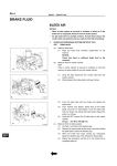
The procedure and diagrams outlined below provide the steps to be followed when replacing the
air filter cartridge in the VESDA LaserPLUS (VLP) and VESDA LaserSCANNER (VLS) detectors:
1.
2.
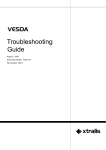
Slide down and remove the air filter cover (A) in Figure 1 below.
Unscrew the recessed phillips head screw (B) in Figure 1 below.
Document No. 10256_07
11
®
VESDA
Maintenance Guide
B
C
Figure 1: Replacing air filters in VLP and VLS detectors
3.
4.
5.
6.
7.
7.2
Pull out the air filter cartridge (C) in Figure 1 above. This will stop the aspirator. If the
aspirator does not stop, replace the filter switch.
Insert the replacement air filter cartridge (VSP-005).
Tighten the filter screw.
Replace the air filter cover.
Reset the filter counter using either the LCD Programmer or a PC running VSC/VSM4.
Replacing the LaserCOMPACT filter cartridge
The service interval of an air filter depends upon the environment. You can use the LCD
Programmer or VESDA PC Software guides to change the service interval for filters. The system
will generate a minor fault when the filter has reached 80% and an urgent fault when it reaches
120% of its capacity. We recommend that the installation date and replacement date are written
on the air filter cartridge label as a physical reminder of when the next service is expected.
Important Note: The detector must have the power turned on when the air filter cartridge is being
replaced.
The procedure and diagrams outlined below provide the steps to be followed when replacing the
air filter cartridge in the VESDA LaserCOMPACT (VLC) detector:
1.
2.
3.
4.
12
Open the front cover
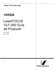
Locate the air filter cartridge (A), inside the detector compartment, as indicated in Figure 2
below.
Undo the recessed phillips head filter screw (B) in Figure 2 below.
Lift out the air filter cartridge.
Document No. 10256_07
®
VESDA
Maintenance Guide
A
B
Figure 2: Replacing the air filter cartridge in VLC detectors
5.
6.
7.
8.
9.
Insert a new air filter cartridge (A) in Figure 2 above.
Tighten the filter screw (B) in Figure 2 above.
Reset the filter counter by connecting a LCD programmer or a PC with VSC software to the
programming socket.
Using a PC only (applicable to RO version) or a PC with a PC-Link HLI (Applicable to VN
version only), reset the filter by entering your user level and PIN number to Log ON to the
detector then Initiate the Reset Filter Settings command located under the device menu.
Close up the detector.
7.3
Replacing the LaserFOCUS filter cartridge
The VESDA LaserFOCUS (VLF) detector uses a disposable dual stage air filter cartridge. This
filter removes dust contamination from sampled air and provides a clean air bleed to preserve the
detector chamber optics. The detector constantly monitors filter efficiency. To maintain the
operational integrity of the smoke detector, it is recommended that the filter be replaced every 2
years or when a filter fault occurs. More frequent filter replacement is necessary in environments
where there are high levels of contamination.
A fault is raised on the detector, when the filter needs to be replaced. During the replacement
process, the detector must be told that a new filter has been installed.
Note:
Prior to any work or maintenance being carried out on the VESDA VLF, take the
necessary steps to advise the monitoring authority that power may be removed and
that the system will be disabled.
Ensure that the area surrounding the filter is clear of dirt and debris, prior to
Document No. 10256_07
13
®
VESDA
Maintenance Guide
replacement.
The filter is for single use only, it cannot be cleaned and re-used.
Ensure that the detector remains powered up during filter replacement and that a
new filter cartridge is available:
The procedure and diagrams outlined below provide the steps to be followed when replacing the
air filter cartridge in the VLF detector:
1.
2.
3.
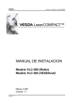
Push in the security tab and lift up the field service access door (A) in Figure 3 below.
Set the detector to 'Standby' mode by pressing the Disable button for 6 seconds. The
Disabled LED begins to flash rapidly. After releasing the Disable button the disabled LED
will flash more slowly.
Undo the recessed retaining screw (C) and pull out the old filter (B) in Figure 3 below.
Legend
A
C
D
A
Field service access door
B
Dual stage air filter cartridge
C
Retaining screw
D
Filter switch
B
Figure 3: Replacing the air filter cartridge in a VLF detector
4.
5.
6.
7.
8.
7.4
Using your finger, firmly press the filter switch (D), in the filter recess of the detector, 5 times
within 5 seconds to confirm with the detector that a new filter is about to be installed (see
inset). A LED next to the serial interface will flash each time you push the filter switch, and
will continue flashing once you have successfully pressed the switch 5 times in 5 seconds.
Insert the new filter (VSP-005) and tighten the retaining screw.
Press the Disable button for 6 seconds to return the detector to normal operating mode.
Record the filter replacement date on the filter.
Close the field service access door.
Replacing LaserPLUS and LaserSCANNER
chassis
You must disassemble the VESDA LaserPLUS (VLP) or VESDA LaserSCANNER (VLS)
detectors, before replacing their chassis, as follows:
14
Document No. 10256_07
®
VESDA
Maintenance Guide
1.
Isolate the detector by pressing the isolate button on the zone configured display or by
selecting "Isolate Zone" from the "Zone" menu in VSC or VSM4. This isolates the output
from the detector to a fire alarm panel or monitoring system.
Save Node Configuration by using VSC or VSM4, highlight the detector in the device tree
window and select "Save Node Configuration" from the "Device" menu.
Turn off the power by disconnecting the power cables.
Remove the front panel by first opening the cover plate and screw covers, then unscrewing
the cover plate screws as shown in Figure 4 below.
2.
3.
4.
Figure 4: Removing the VLP or VLS front cover for chassis replacement
5.
Disconnect the data cables that connect the chassis assembly to the termination card.
These include the front panel modules (if fitted) and manifold (behind chassis). Refer to
Figure 5, “Removing data cables for VLP or VLS chassis replacement,” on page 15.
Important Note: Performing this step with live power can result in lost detector calibration data.
Should this occur, detector warranties shall be void and service charges will be incurred.
D
Figure 5: Removing data cables for VLP or VLS chassis replacement
6.
7.
Unscrew the 2 recessed retaining screws (D) in the Figure 5 above.
Remove the chassis, holding the chassis by the aspirator assembly. Release the two lower
locking tabs by lifting the chassis upward and pulling outward. Use a screwdriver to assist
with tab release if necessary. Refer to Figure 6 below.
Document No. 10256_07
15
®
VESDA
Maintenance Guide
Note:
The part number for the VLP chassis is VSP-006; for the VLS chassis, the part
number is VSP-009.
Figure 6: Removing the VLP or VLS chassis
Caution:
Care must be taken not to damage the cable running to the manifold.
Note:
The detection chamber, head processor card and flow sensors are factory
calibrated as a matched set. Separating the set and replacing it with components
from another set may cause the Detector to malfunction, requiring re-calibration at
the factory.
8. Disconnect the flow sensor lead.
9. Unscrew the manifold retaining screws.
10. Remove the Manifold by sliding it downward, away from the pipe network as shown in
Figure 7.
Figure 7: Removing Pipe Inlet Manifold during VLP and VLS chassis replacement
11. Attach the replacement Manifold and Chassis by reversing the procedure above.
Note:
16
Ensure that power is turned off before reconnecting Data cables. All Data cables
must be connected properly before power is turned on. Failure to observe this
requirement may cause data corruption that requires factory re-calibration.
Document No. 10256_07
®
VESDA
Maintenance Guide
12. Configure the Node using VSC or VSM4 by highlighting the Detector in the Device Tree
Window and highlighting "Restore Node Configuration" from the Device Menu, or
reprogram the detector using the LCD Programmer.
7.5
Replacing LaserPLUS and LaserSCANNER
aspirators
When replacing the VESDA LaserPLUS (VLP) or VESDA LaserSCANNER (VLS) detector
aspirators, follow the instructions below:
1.
2.
3.
4.
Isolate and power down the detector.
Open the front cover.
Locate and unplug the cable loom that connects from the head processor card (HPC) to one
of the modules located on the front panel. Mark out this connector position, if unsure about
the cabling.
Remove the air filter cartridge, refer to Figure 7, “Removing Pipe Inlet Manifold during VLP
and VLS chassis replacement,” on page 16.
Figure 8: Removing the Air Filter Cartridge for VLP or VLS aspirator replacement
5.
Remove the HPCs securing screw.
Warning:
6.
7.
Hold the HPC at the edges. Static charges may damage it.
Remove the brown insulating sheet and lift up the HPC.
Locate the aspirator cable loom (red, white and blue wires) and disconnect the connector
from the HPC.
Document No. 10256_07
17
®
VESDA
Maintenance Guide
B
Legend
C
D
A
Filter switch connector
socket
B
Aspirator loom connector
C
Aspirator locking fingers
D
Move both locking fingers
outwards
E
Aspirator (Lift upwards)
E
A
Figure 9: Removing the HPC and Disconnecting the aspirator cable loom
8. Locate the two plastic fingers securing the aspirator to the chassis (D) in Figure 9 above.
9. Push fingers outwards (E) and lift the aspirator out.
10. Remove the exhaust pipe elbow and filter card assembly (A) from the aspirator (B) as
shown in Figure 10, “Removing the Exhaust Pipe Elbow and Aspirator,” on page 18.
Legend
A
Exhaust pipe elbow with
filter card switch
B
Aspirator
A
B
Figure 10: Removing the Exhaust Pipe Elbow and Aspirator
11. Reattach the exhaust pipe elbow and filter card assembly (A) to the aspirator (B) exhaust
outlet as shown in Figure 10 above.
12. Wipe the manifold outlet flange surface if dirty.
13. Slide the aspirator between the fingers until fingers lock over aspirator. Check that the
aspirator does not come off when lifted.
14. Reconnect the aspirator cable loom to the cable socket on the HPC.
15. Secure the HPC to the chassis, ensuring that the card locks under the plastic fingers.
16. Place the insulating sheet over the HPC and secure it with the screw.
17. Re-attach the air filter cartridge.
18. Re-connect the cable loom to the module on the front panel.
19. Check that all wires are secured to the connectors or terminals.
20. Power up the detector and check the aspirator is running.
18
Document No. 10256_07
®
VESDA
Maintenance Guide
21. Close the detector, refer to Figure 4, “Removing the VLP or VLS front cover for chassis
replacement,” on page 15.
7.6
Replacing the LaserCOMPACT aspirator
Aspirators, in VESDA LaserCOMPACT (VLC) detectors are replaced as follows:
1.
2.
3.
4.
5.
6.
7.
8.
Isolate and power down the detector.
Remove the four screws securing the termination card.
Disconnect the aspirator cable loom from the connector on the aspirator.
Gently pull the termination card out, away from the interface card (connected behind). Take
care not to dislodge any wires connected to the termination card and leave it suspended by
these wires.
Remove the air hose from the aspirator pipe by pulling.
Undo the three Phillips head screws securing the aspirator; these screws are captive.
Turn the aspirator anti-clockwise, using the exhaust port as the pivot point.
Push the aspirator upward to remove it.
Figure 11: Replacing the Aspirator in a VLC detector
9.
10.
11.
12.
13.
14.
15.
16.
17.
Check that the new aspirator has a gasket on the inlet flange and three attached screws.
Wipe the manifold outlet flange surface.
Secure the aspirator with the three screws.
Reconnect the previously removed air hose to the pipe on the aspirator. Ensure a tight fit
over the pipe.
Reinsert the termination card into the interface card.
Secure the termination card with the four screws.
Connect the aspirator cable connector to the socket on the aspirator; the connector is keyed
and can only be inserted one way.
Check that all wires are secured to their connectors or terminals.
Power up the detector and check that the aspirator is running.
Document No. 10256_07
19
®
VESDA
Maintenance Guide
18. Resolve all Fault conditions.
19. Close the detector.
20. Reset Isolate to normal conditions and check that the airflow % has returned to the level it
was at before Disassembly.
7.7
Replacing the LaserFOCUS aspirator
Important Note: Prior to replacing the aspirator, advise the monitoring authority that power is to
be removed and the system disabled.
Caution:
Electrostatic discharge precautions need to be taken, prior to removing the front
cover from the detector, otherwise damage may occur.
The following Aspirator removal instructions assume normal mounting, refer to Figure 12 below:
1.
2.
3.
4.
5.
6.
Disconnect power to the detector.
Push in the security tab and lift up the field service access door.
Unscrew the two front cover retaining screws, lift and swing down the front cover.
Only disconnect the fan wiring loom from the connection point (E) at the aspirator.
Undo the retaining screw on the aspirator (A).
Swing the aspirator out then lift and remove it from the detector.
Note:
Any time the aspirator is removed ensure that the area surrounding it is clear of dirt
and debris before it is replace.
Care must be taken, during aspirator replacement. The aspirator must be correctly
seated; this is essential to ensure that gaskets are not damaged or dislodged from
the underside of the aspirator.
7.
8.
9.
10.
11.
12.
20
Clip the aspirator (VSP-715) into the retaining clip (D) and swing it back into the detector.
Tighten the retaining screw (A) but do not over tighten.
Reconnect the fan loom to the aspirator (E).
Replace the front cover and screw it into place.
Close the field service access door.
Reconnect the power to the detector.
Document No. 10256_07
®
VESDA
Maintenance Guide
Legend
A
B
A
Aspirator securing screw
B
Swing aspirator out to remove
C
Aspirator
D
Retaining clip points
E
Fan loom connector must be
disconnected here
C
D
E
Figure 12: Replacing the aspirator in a VLF detector
7.8
Replacing LaserPLUS and LaserSCANNER
termination cards
Important Note: Disconnect the detector power supply before commencing replacement of the
termination card. Only reconnect the 24 VDC power supply once the replacement termination
card is secured.
Follow the instructions below to replace the VLP or VLS termination cards.
1.
2.
3.
4.
5.
6.
7.
8.
Mark out the wire positions on each terminal socket before removing them.
Remove all terminal plugs (C) from sockets, leaving the wires attached to the plugs, refer to
Figure 13 below.
Remove the 10 wire and 13 wire cable looms from their socket (B) in Figure 13 below.
Remove the five Phillips head screws (A) in Figure 13 below.
Remove the termination card.
Attach the Termination Card with five Phillips head screws (A).
Reattach the 10 wire and 13 wire cable looms to the sockets. (B) The connectors can only
be inserted into the socket one way. Turn the connector around if the connector does not fit
into its socket.
Reconnect the terminal plugs to their sockets, ensuring the plugs are connected to their
correct socket (C).
Document No. 10256_07
21
®
VESDA
Maintenance Guide
C
A
B
Figure 13: Replacing VLP/VLS head termination cards
7.9
Replacing the LaserCOMPACT termination card
Follow the instructions below to replace the VESDA LaserCOMPACT (VLC) detector termination
card:
1.
Remove the front cover of the detector (refer to Figure 2, “Replacing the air filter cartridge in
VLC detectors,” on page 13).
2. Isolate and power down the detector before you begin.
3. Record all wiring connections to the termination card so that you can connect the
replacement card properly.
4. Disconnect the wiring for power, communications and relays from the 45 deg screw
terminals.
5. Remove the four screws securing the termination card.
6. Disconnect the 3-way aspirator cable loom from the connector on the termination card.
7. Disconnect the 5-way front panel LED cable from the termination card.
8. Gently pull the termination card away from the interface card (connected behind).
9. Secure the replacement termination card with the four screws.
10. Reconnect the 3-way aspirator cable loom to the connector on the termination card.
11. Reconnect the 5-way front panel LED cable to the termination card.
Note:
12.
13.
14.
15.
16.
17.
22
Both the 3-way aspirator cable and the 5-way front panel LED cable are keyed so
that they can only be connected in one orientation.
Reconnect the wiring for power, communications and relays to the 45 deg screw terminals.
Check that all wires are secured to their correct terminals.
Power up the detector and check that the aspirator is running.
Resolve all Fault conditions.
Close the detector.
Reset Isolate to normal conditions and check that the airflow % has returned to the level it
was at before disassembly.
Document No. 10256_07
®
VESDA
Maintenance Guide
7.10 Replacing LaserPLUS and LaserSCANNER
detector modules
Important Note: Isolate and power down the detector before you begin.
Follow the instructions below to replace VESDA LaserPLUS (VLP) and VESDA LaserSCANNER
(VLS) detector modules:
1.
2.
3.
4.
5.
6.
Insert a screwdriver at the top between the Module and the Front Cover (refer to Figure 4,
“Removing the VLP or VLS front cover for chassis replacement,” on page 15),
Gently remove the module from the front cover by levering the screwdriver.
Disconnect the wire loom from the module processor card.
Connect the wire loom to the respective 10 or 11 way connector(s) on the module processor
card.
Secure the modules to the front cover by gently snapping the module into place ensuring
that none of the EMC Screening is trapped.
Power up the detector.
7.11 Inspecting and cleaning LaserSCANNER valves
The VESDA LaserSCANNER has four valves that open and close to allow the detector to draw
air from one sample pipe at a time. Since the air that reaches the valves has not been filtered, it
may contain dust, dirt, and background pollution such as soot or coal dust.
To inspect and clean VLS valves, follow the instructions below:
1.
2.
Remove the pipes leading into the VLS detector.
Press, and hold down, the Silence/Scan button on the front of your VLS detector. The valve
scan test will start. If your VLS does not have a Silence/Scan button, use your PC and
VESDA System Configurator (VSC) to start the valve scan test (step 3 to 6).
3. Logon to VSC
4. Select the VESDA Laser Scanner detector from the Device Tree
5. Select Device from the Main Menu
6. Select Start Manual Scan Test. A dialogue box confirms that you wish to proceed with the
test. Select Yes to continue.
7. Once the valve scan test is complete, look inside the inlet ports to see that the valves are
periodically opening and closing. Also look for evidence of a build-up of dirt.
8. If dirt is found, you will need to remove the chassis before flushing the valves. Refer to
Replacing LaserPLUS and LaserSCANNER chassis on page 14 for details.
9. Remove the air inlet manifold and clean it with compressed air. The manifold is sensitive so
do not clean with more than 87 KPa (6 bar) compressed air.
10. Once clean, reassemble the detector and perform a test to ensure system integrity.
Document No. 10256_07
23
Maintenance Guide
24
®
VESDA
Document No. 10256_07
®
VESDA
Maintenance Guide
Appendix A: Laser Products Parts List
Category
Part number
Description
VLP
VSP-000
Blank plate, non-EMC painted, with VESDA logo
VSP-001
Programmer Module
VSP-002
Display Module
VSP-005
Filter Cartridge
VSP-006
VLP Detector Chassis Assembly complete with Manifold
VSP-013
Detector Cover Assembly complete with EMC shields
VSP-014
7-relay Head Termination Card (HTC7)
VSP-015
VLP Detector Aspirator Assembly
VSP-019
Filter Cover
VSP-021
Imperial Pipe Adaptors (25 mm to 27 mm) (4 off) (US only)
VSP-100
Blank plate with FIRE 1 & OK LEDs, non-EMC painted, with
VESDAlogo
VSP-101
Blank plate with French FIRE 1 & Fault (FF) LEDs, non-EMC painted,
with Printed logo
VSP-200
Blank plate, EMC painted, without VESDA logo
VSP-540
Exhaust Deflector (black)
VSP-000
Blank plate, non-EMC painted, with VESDA logo
VSP-001
Programmer Module
VSP-004
Scanner Display Module
VSP-005
Filter Cartridge
VSP-009
Scanner Chassis Assembly complete with Manifold
VSP-013
Detector Cover Assembly complete with EMC shields
VSP-014
7-relay Head Termination Card (HTC7)
VSP-015
VLP Detector Aspirator Assembly
VSP-016
12-relay Head Termination Card (HTC12)
VSP-019
Filter Cover
VSP-021
Imperial Pipe Adaptors (25 mm to 27 mm) (4 off) (US only)
VSP-100
Blank plate with FIRE 1 & OK LEDs, non-EMC painted, with
VESDAlogo
VSP-101
Blank plate with French FIRE 1 & Fault (FF) LEDs, non-EMCpainted,
with Printed logo
VSP-200
Blank plate, EMC painted, without VESDA logo
VSP-540
Exhaust Deflector (black)
VLS
Document No. 10256_07
25
®
VESDA
Maintenance Guide
Category
Part number
Description
VLC
VSP-005
Filter Cartridge
VSP-021
Imperial Pipe Adaptors (25 mm to 27 mm) (4 off) (US only)
VSP-501
VLC Aspirator
VSP-502
VLC VN Remote Display Module
VSP-509
VESDAlink™ RS232 9-pin to 9-pin Serial Cable
VSP-510
VLC RO Termination Card (CTC-RO)
VSP-515
VLC VN Termination Card (CTC-VN)
VSP-540
Exhaust Deflector (black)
VSP-005
Filter Cartridge
VSP-021
Imperial Pipe Adaptors (25 mm to 27 mm) (4 off) (US only)
VSP-540
Exhaust Deflector (black)
VSP-702
VLF Remote Display Module
VSP-715
VLF Aspirator
VSP-001
Programmer Module
VSP-002
Display Module
VSP-004
Scanner Display Module
VSP-007
0-relay Remote termination card (RTC0)
VSP-008
7-relay Remote termination card (RTC7)
VSP-016
12-relay Head Termination Card (HTC12)
VSP-200
Blank plate, EMC painted, without VESDA logo
VSP-208
12-relay Remote termination card (RTC12)
VSP-300
Blank plate, non-EMC painted, without VESDA logo
VSP-003
VESDAnet Socket Kit
VSP-102
Detector Relay Processor Module (Blank + DRP)
VSP-103
Scanner Relay Processor Module (Blank + DRP)
VSP-200
Blank plate, EMC painted, without VESDA logo
VSP-300
Blank plate, non-EMC painted, without VESDA logo
VLF
Modules
Accessories
26
Document No. 10256_07
Fully enclosed, and strictly no leakage, fully air-conditioned, usually with
HEPA filters fitted, strictly maintained to high standards of cleanliness
such as Clean Room classification 1, 10,100 in accordance with US
Federal Standard 209D, computer rooms with restricted access, medical
facilities with positive pressure, installations within medical and
semiconductor equipment etc.
Fully enclosed and usually air-conditioned with some filters fitted, high
airflow extraction systems or standalone AHU, routinely maintained to
acceptable health recommendations for occupants. Frequent access. May
be multi-function facility. General office building, telecommunication base
station, equipment switch rooms, shopping mall, heritage building,
churches, document storage and general warehouse type building
(including cold storages) with high ceiling.
Similar to Environment Class 2 in countries with high levels of pollution
and no filtration of outside air. Facilities with light industrial sites,
manufacturing and processing without noticeable airborne particles,
prison cells, etc.
Partially enclosed, no air-conditioning but may use extraction system from
time to time.Usually industrial sites with noticeable air pollution, loading
bays, dusty production, underground platform, equipment rooms, facilities
using natural air ventilation.
Open environments, airborne particle clearly visible, sometime require
wash-down to maintain acceptable health standard for occupants. May
use extensive stage smoke or fog.Applications like amusement park rides,
coal fired power station, fertiliser factory, waste-treatment, tunnels, bus
terminals, etc.
2
3
4
5
Typical Application
1
Environment
Class
At least every 24
months (code
requirements
typically call for
12 month Service
Intervals
At least every 24
months (code
requirements
typically call for
12 month Service
Intervals)
At least every 12
months
At least every 12
months
At least every 6
months
At least every 36
months
At least every 24
months
At least every 18
months
At least every 12
months
Usually between
0.006-0.009% obs/m
{0.002-0.003%
obs/ft}
Usually less than
0.015% obs/m
{<0.005% obs/ft}
Usually less than
0.03% obs/m
{<0.01% obs/ft}
Usually above
0.03% obs/m
{>0.01% obs/ft}
Recommended
Maintenance
Period
At least every 60
months
Recommended
Filter
Replacement
Frequency
Usually less than
0.006% obs/m
(average)
{<0.002% obs/ft}
(average)
Background
Smoke Level
Appendix B: Recommended frequencies for general maintenance
and filter cartridge replacement
Document No. 10256_07
®
Refer to Class 6 (Special
Case). May require watertrap in high humidity climate.
High relative humidity,
frequent wash-down.May
require water-trap in high
humidity climate.
Low ceiling, higher airborne
particles level, high relative
humidity. May require water
trap in high humidity climate.
Frequent access and/or
excessive building leakage/
doors connected to a highly
polluted ambient
environment, infrequent
HVAC maintenance, high
relative humidity, activities
such as cooking, production,
dusty spaces like ceiling
void, suspension floor,
regular wash downs.
Higher clean room
classification, protection of
other areas such as wet
bench, subject to
contamination due to
frequent access or minor
building leakage
Factors that may affect
filter replacement
frequency.
Recommendations of use
VESDA
Maintenance Guide
27
28
6(Special
Cases)
Environment
Class
Usually fits within "High" and "Extreme" definitions. Regular fumigation
(such as tobacco storage), corrosive, radiative, irregular process, high
level of fine dusty environment such ascement, textile, welding, oily,
steamy, etc.
Typical Application
Varied
Background
Smoke Level
Closely monitor
for the first 3 to 6
months to
develop a filter
replacement
guideline
Recommended
Filter
Replacement
Frequency
Closely monitor
for the first 3 to 6
months to
develop a
maintenance
schedule
Recommended
Maintenance
Period
Consult with Risk Manager,
refer to local codes,
standards and regulations to
ensure compliance.Regular
smoke tests are required.
May require water-trap in
high humidity climate.
Factors that may affect
filter replacement
frequency.
Recommendations of use
Maintenance Guide
VESDA
®
Document No. 10256_07
®
VESDA
Maintenance Guide
Appendix C: Example Of A Typical Maintenance Log
Customer:
Date of visit:
Site:
Technician’s name:
Service company name:
Address:
Phone number:
Visit type:
scheduled / fault call out / annual test (circle appropriate visit)
VESDA detector type:
Detector serial no.:
Detector location:
Before you record any more information:
1. Record airflow
use table below
2. Download and save event log via VSC
Yes / No
3. Download and save configuration file via VSC
Yes / No
4. Give a copy of event log and configuration file to site manager
Yes / No
Flow (before):
%
actual
Flow (after):
Pipe 1
Pipe 1
Pipe 2
Pipe 2
Pipe 3
Pipe 3
Pipe 4
Pipe 4
Detector faults present:
Actions to fix:
Parts replaced:
Clean pipes:
filter
others
Have you done the following?
Document No. 10256_07
Yes / No
%
actual
pipe flush
Yes / No
in-pipe sampling holes
Yes / No
capillaries
Yes / No
Comments
29
®
VESDA
Maintenance Guide
reviewed service history
Yes / No
checked power supply/UPS
Yes / No
checked battery backup
Yes / No
checked battery charging
Yes / No
tested fire alarm and fault notification at detector
Yes / No
tested fire alarm and fault notification at monitoring system
Yes / No
compared current results to commissioning data
Yes / No
returned the system to normal operation mode
Yes / No
Record any other activities undertaken:
Circle the detector's environment class:
1
2
3
Record filter replacement frequency:
months
Exp. Date
Record detector maintenance period:
months
Next visit:
4
5
6
Signatures:
30
Technician:
Site Manager:
Date:
Date:
Document No. 10256_07