Download Caution! - Elektrosistem

Transcript
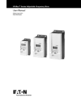
M-Max Series
adjustable frequency drive
User Manual
Effective November 2009
Danger!
Dangerous electrical voltage!
Before commencing the installation
• Disconnect the power supply of the device.
• Ensure that devices cannot be accidentally restarted.
• Verify isolation from the supply.
• Earth and short circuit the device.
• Cover or enclose any adjacent live components.
• Follow the engineering instructions (IL04020001E) for the
device concerned.
• Only suitably qualified personnel in accordance with
EN 50110-1/-2 (VDE 0105 Part 100) may work on this
device/system.
• Before installation and before touching the device ensure
that you are free of electrostatic charge.
• The functional earth (FE, PES) must be connected to the
protective earth (PE) or the potential equalisation. The system
installer is responsible for implementing this connection.
• Connecting cables and signal lines should be installed so
that inductive or capacitive interference does not impair the
automation functions.
• Install automation devices and related operating elements in
such a way that they are well protected against unintentional
operation.
• Suitable safety hardware and software measures should be
implemented for the I/O interface so that an open circuit on the
signal side does not result in undefined states in the
automation devices.
• Ensure a reliable electrical isolation of the extra-low voltage of
the 24 V supply. Only use power supply units complying with
IEC 60364-4-41 (VDE 0100 Part 410) or HD384.4.41 S2.
• Deviations of the mains voltage from the rated value must
not exceed the tolerance limits given in the specifications,
otherwise this may cause malfunction and dangerous
operation.
• Measures should be taken to ensure the proper restart of
programs interrupted after a voltage dip or failure. This should
not cause dangerous operating states even for a short time.
If necessary, emergency-stop devices should be implemented.
• Wherever faults in the automation system may cause injury or
material damage, external measures must be implemented to
ensure a safe operating state in the event of a fault or
malfunction (for example, by means of separate limit switches,
mechanical interlocks etc.).
• Depending on their degree of protection, adjustable frequency
drives may contain live bright metal parts, moving or rotating
components or hot surfaces during and immediately after
operation.
• Removal of the required covers, improper installation or
incorrect operation of motor or adjustable frequency drive may
cause the failure of the device and may lead to serious injury or
damage.
• The applicable national accident prevention and safety
regulations apply to all work carried on live adjustable
frequency drives.
• The electrical installation must be carried out in accordance
with the relevant regulations (e. g. with regard to cable cross
sections, fuses, PE).
• Transport, installation, commissioning and maintenance work
must be carried out only by qualified personnel (IEC 60364,
HD 384 and national occupational safety regulations).
• Installations containing adjustable frequency drives must be
provided with additional monitoring and protective devices in
accordance with the applicable safety regulations.
Modifications to the adjustable frequency drives using the
operating software are permitted.
Eaton Corp.
Safety instructions
• Emergency stop devices complying with IEC/EN 60204-1 must
be effective in all operating modes of the automation devices.
Unlatching the emergency-stop devices must not cause a
restart.
• Devices that are designed for mounting in housings or control
cabinets must only be operated and controlled after they have
been installed and with the housing closed. Desktop or
portable units must only be operated and controlled in
enclosed housings.
I
• All covers and doors must be kept closed during operation.
• To reduce the hazards for people or equipment, the user must
include in the machine design measures that restrict the
consequences of a malfunction or failure of the drive
(increased motor speed or sudden standstill of motor).
These measures include:
– Other independent devices for monitoring safety-related
variables (speed, travel, end positions etc.).
– Electrical or non-electrical system-wide measures
(electrical or mechanical interlocks).
– Never touch live parts or cable connections of the adjustable
frequency drive after it has been disconnected from the
power supply. Due to the charge in the capacitors, these
parts may still be live after disconnection. Fit appropriate
warning signs.
II
MN04020001E
Contents
About This Manual
Writing Conventions
Abbreviations and Symbols
– Units
1
2
M-Max Series
5
5
6
6
System overview
Checking the Delivery
Rating and Rating Plate
– Key to part numbers
– General rated operational data
– Technical data
M-Max Designation
Features
Selection criteria
Proper use
Maintenance and inspection
Service and warranty
7
7
8
9
10
12
14
16
17
18
20
20
20
Introduction
Electrical power network
– Mains connection and configuration
– Mains voltage and frequency
– Voltage balance
– Idle power compensation devices
– Mains reactors
Safety and switching
– Fuses and cable cross-sections
– Cables and fuses
– Residual-current device
– Mains contactor
EMC measures
Motor and Application
– Motor selection
– Connecting motors in parallel
– Motor and circuit type
– Bypass operation
– Connecting EX motors
21
21
22
22
22
22
23
23
24
24
24
24
25
26
27
27
27
28
29
29
Engineering
1
MN04020001E
3
Installation
Introduction
Installation guidelines
– Mounting position
– Cooling measures
– Fixing
EMC-compatible installation
– EMC measures in the control panel
– Grounding
– Shielding
Electrical Installation
– Power section connections
– Arrangement and connection of the power terminals
– Connection on control section
– Arrangement and connection of the control
signal terminals
– Function of the control signal terminals
– Block diagram
– Insulation testing
4
Operation
Checklist for commissioning
Hazard warnings
Commissioning with control signal terminals
(factory setting)
– Brief Instructions
5
Error and Warning Messages
Introduction
– Error messages
– Fault log (FLT)
– Alarm messages
6
Parameters
Control unit
– Display unit
– General information on menu navigation
– Setting parameters
Parameter menu (PAR)
– Parameter selection (P1)
– Analog input (P2)
– Digital input (P3)
– Analog output (P4)
– Digital output (P5)
– Drives control (P6)
– Motor (P7)
– Protective functions (P8)
– PI controller (P9)
– Fixed frequency setpoint value (P10)
– V/Hz-characteristic curve (P11)
– Braking (P12)
– System parameter
Operational data indicator (MON)
Setpoint input (REF)
2
31
31
31
31
31
32
35
35
35
35
37
38
40
42
43
44
49
51
53
53
54
55
58
61
61
61
61
61
65
65
66
66
67
69
71
73
75
78
79
80
84
86
89
91
93
96
99
101
103
MN04020001E
7
Serial interface (Modbus RTU)
Introduction
– Operating mode Modbus RTU
– Modbus Process Data
– Output process data
– Input process data
– Bit Definition
105
105
107
107
108
108
109
Special technical data
Dimensions and frame size
Cables and fuses
List of parameters
– Quick configuration (basis)
– All Parameters
111
111
115
117
118
118
120
Appendix
Index
127
3
MN04020001E
4
MN04020001E
About This Manual
This manual provides a description of the adjustable frequency
drives of the M-MaxTM Series. It provides special information
required for project planning, installation and for the operation of
the MMX adjustable frequency drive. All information applies to the
specified hardware and software versions.
Please read the manual thoroughly before you install and operate
the adjustable frequency drive.
h All the specifications in this manual refer to the hardware
and software versions documented in it.
h More information on the series described here can be
found on the Internet under:
www.eaton.com/M-Max
We assume that you have a good knowledge of engineering
fundamentals and that you are familiar with handling electrical
systems and machines, as well as with reading technical drawings.
Writing Conventions
The symbols used in this manual have the following meanings:
X
Indicates instructions to be followed
h Indicates useful tips and additional information.
h
Caution!
Warns about the possibility of minor property damage.
i
Warning!
Warns about the possibility of serious property damage
and minor injuries.
j
Danger!
Warns about the possibility of major property damage
and serious injuries or death.
h In order to make it easier to follow the manual, the name
of the current chapter is shown in the header of the lefthand page and the name of the current section is shown
in the header of the right-hand page. This does not apply
to pages at the start of a chapter or to empty pages at the
end of a chapter.
h In order to make it easier to understand some of the
figures included in this manual, the housing of the
adjustable frequency drive, as well as other safetyrelevant parts, have been left out. However, it is
important to note that the adjustable frequency drive
must always be operated with its housing placed properly,
as well as with all required safety-relevant parts.
h Please follow the installation instructions in the
IL04020001E installation instructions document.
h This manual was created in an electronic format. You can
also order a hard copy version of it.
5
MN04020001E
Abbreviations and Symbols
The abbreviations and symbols used in this manual have the
following meanings:
EMC
Electromagnetic compatibility
FS
Frame Size
GND
Ground, 0-V-Potential
IGBT
Insulated-gate bipolar transistor
PDS
Power Drives System
PES
EMC connection to PE for shielded lines
PNU
Parameter number
UL
Underwriters Laboratories
M-Max adjustable frequency drives are divided into three voltage
categories:
• 115 V (MMX11)
• 200 V (MMX12…, MMX32…)
• 400 V (MMX34…)
These voltage categories are based on standardized nominal line
voltage values (IEC 60038, VDE 017-1) at the electric utility's
(EVU) supply terminal:
• 115 V A 115 V ±10 % (50/60 Hz)
• 200 V A 230 V ±10 % (50/60 Hz)
• 400 VV
A 400 V ±10 % (50/60 Hz)
The wide tolerance range of adjustable frequency drive M-Max
takes into account a permissible voltage drop of an additional 4 %
(ULN - 14 %) in load networks, while, in the 400 V category, it
takes into account the North American line voltage of 480 V +10
% (60 Hz).
The permissible connection voltages for the M-Max series are
listed in the Technical Specifications section in the appendix.
Units
Every physical dimension included in this manual uses
international metric system units, otherwise known as SI (Système
international d’unités) units. For the purpose of the equipment's
UL certification, some of these dimensions are accompanied by
their equivalents in imperial units.
Table 1:
6
Unit conversion examples
Designation
US-American value
SI value
Conversion value
US-American
designation
Length
1 inch (’’)
25.4 mm
0.0394
inch
Power
1 HP = 1.014 PS
0.7457 kW
1.341
horsepower
Torque
1 lbf in
0.113 Nm
8.851
pound-force inches
Temperature
1 °F (TF)
-17.222 °C (TC)
TF = TC × 9/5 + 32
Fahrenheit
Speed
1 rpm
1 rpm
1
revolutions per minute
Weight
1 lb
0.4536 kg
2.205
pound
MN04020001E
1 M-Max Series
System overview
a
BACK
RESET
OK
LOC
REM
I
d
f
COMM
ERROR
AC DRIVE
e
Figure 1: System overview
a
b
c
d
Adjustable frequency drives MMX-…
Line reactor, Load reactor, Sinusoidal filter
Braking resistor
Communication module MMX-COM-PC
7
MN04020001E
Checking the Delivery
h Before opening the packaging go over the ratings plate on
the packaging and check for whether the delivered
adjustable frequency drive is the same type as the one you
ordered.
M-Max adjustable frequency drives have been carefully packaged
and prepared for delivery. These devices should only be shipped in
their original packaging with suitable transportation materials.
Please take note of the labels and instructions on the packaging,
as well as of those meant for the unpacked device.
Open the packaging with adequate tools and inspect the contents
immediately after receipt in order to ensure that they are complete
and undamaged.
The packaging must contain the following parts:
•
•
•
•
an M-Max adjustable frequency drive,
an accessory kit for EMC-suitable installation
installation instructions IL04020001E
a data carrier (CD-ROM) with documentation
and parameter configuration software
CD
BACK
RESET
OK
LOC
REM
I
Figure 2: Scope of supply
8
MN04020001E
Rating and Rating Plate
Label
Meaning
The rating for M-Max adjustable frequency drives is indicated on
the corresponding rating plate, located on the side of the device.
MMX34AA3D3F0-0
Part no.:
MMX = M-Max series adjustable frequency
drive
3 = Three-phase power connection
4 = 400 V voltage category
AA = Instance (Software version A and
alphanumerical display)
3D3 = 3.3 A rated operational current
(3-decimal-3)
F = Integrated radio interference
suppression filter
0 = IP20 protection type
0 = No integrated optional assembly
Input
Power connection rating:
Three-phase AC voltage (Ue 3~ AC),
380 - 480 V voltage, 50/60 Hz frequency,
input phase current (4.0 A)
Output
Load side (motor) rating:
Three-phase AC voltage (0 - Ue), output
phase current (3.3 A), output frequency
(0 - 320 Hz)
Motor
Assigned motor rating
1.1 kW at 400 V/1.5 HP at 460 V for a fourpole internally-cooled or surface-cooled
three-phase asynchronous motor
(1500 rpm at 50 Hz/ 1800 rpm at 60 Hz)
S/N
Serial number
a
adjustable frequency drive is an electrical
apparatus.
Read the manual (in this case IL04020001E)
before making any electrical connections
and commissioning.
Figure 3: Rating plate on side of device
Max amb. 50 °C
The maximum ambient temperature during
operation may not exceed +50 °C.
Figure 4: M-Max adjustable frequency drive rating plate (example)
The inscription of the nameplate has the following meaning
(example):
9
MN04020001E
Key to part numbers
The type designation code and the part no. of the M-Max
adjustable frequency drive series are in the following order:
MMX 3
4
AA
1D3
F
0
- 0
Explanation
0 = No optional assembly integrated
1 = Optional assembly integrated
0 = IP20 protection type
1 = Protection type IP21, NEMA 1
F = Radio noise filter (internal)
N = Without internal radio noise filter (No filter)
Rated operational current
1D3 = 1.3 A (D = decimal)
011 = 11 A
AA = Specification (Software version, display unit)
Voltage categories
1 = 100 V (110 V – -15 % to 115 V + +10 %)
2 = 200 V (208 V – -15 % to 240 V + +10 %)
4 = 400 V (380 V – -15 % to 480 V + +10 %)
1 = Single-phase power supply
3 = Three-phase mains supply voltage
MMX = M-Max series adjustable frequency drive
Figure 5: Type designation code of the M-Max adjustable frequency
drive
10
MN04020001E
Examples
Label
Meaning
MMX12AA1D7F0-0
M-Max series adjustable frequency drive:
1 = Single-phase mains connection
2 = Rated voltage 230 V
AA = Software version
1D7 = 1.7 A (rated current)
F = Integrated radio noise filter
0 = IP20 protection type
-0 = No integrated optional assembly
MMX32AA2D4F0-0
M-Max series adjustable frequency drive:
3 = Three-phase power connection
2 = Rated voltage 230 V
AA = Software version
2D4 = 2.4 A (rated current)
F = Integrated radio noise filter
0 = IP20 protection type
-0 = No integrated optional assembly
MMX34AA012F0-0
M-Max series adjustable frequency drive:
3 = Three-phase power connection
4 = Rated voltage 400 V
AA = Software version
012 = 12 A (rated current)
F = Integrated radio noise filter
0 = IP20 protection type
-0 = No integrated optional assembly
11
MN04020001E
General rated operational data
Technical data
Unit
Value
General
Standards and regulations
EMC: IEC/EN61800-3,
Safety: IEC/EN61800-5, UL508C
Certifications and manufacturer's declarations on conformity
EMC: CE, CB, c-Tick
Safety: CE, CB, UL, cUL
Production quality
RoHS, ISO 9001
Climatic proofing
< 95 %, average relative humidity, non-condensing (EN50178)
Air quality
Chemical vapors
IEC721-3-3: Device in operation, Class 3C2
Mechanical particles
IEC721-3-3: Device in operation, Class 3S2
Ambient temperature
Operation
°C/°F
-10 – +501) / +14 – +1221)
Storage
°C/°F
-40 – +70 / -40 – +158
H
0 – 1000 m above sea level, over 1000 m with 1 % power reduction per
100 m, maximum 2000 m with corner grounding, maximun 4700 m with
non-corner grounding, max. +50 °C ambient temperature
Installation altitude
Mounting position
Vertical (± 90 degrees lateral rotation)
Protection type
IP 20
Protection against direct contact
BGV A3 (VBG4, finger and back-of-hand safe)
Over-voltage category/degree of pollution
-
Mechanical shock resistance
IEC 68-2-27
Storage and transport: 15 g, 11 ms (in the packaging)
UPS drop test (for applicable UPS weights)
Vibration
EN 60068-2-6
3 – 150 Hz, oscillation amplitude 1 mm (Peak) at 3 – 15.8 Hz,
maximum acceleration amplitude 1 g at 15.8 – 150 Hz
Emitted interference with internal EMC filter
(maximum motor cable length)
C2: Class A in 1st environment (residential area with commercial
utilization)
C3: Class A in 2nd environment (Industrial)
C2 (5 m), C3 (30 m)
MMX11, MMX12, MMX32, MMX34
Power section
Rated operational voltage
at 50/60 Hz
MMX11
Ue
1 AC 115V
MMX12
Ue
1 AC 230 V (177 – 264 ±0 %)
MMX32
Ue
3 AC 230 V (177 – 264 ±0 %)
MMX34
Ue
3 AC 400 V (323 – 528 ±0 %)
Mains network configuration (AC power supply network)
Center-point grounded star network (TN-S network)
Phase grounded AC networks are not permitted.
Mains switch-on frequency
Maximum one time per minute
Mains current
THD
max. < 50 kA
Short-circuit current
Mains frequency
fLN
50/60 Hz (45 – 66 Hz ±0 %)
Pulse frequency (switching frequency of the inverter)
fPWM
1 kHz – 16 kHz (WE: 6 kHz)1)
Operating mode
Output voltage
12
>120 %
V/Hz-characteristic curve control (WE), sensorless vector control (open loop)
U2
3 AC Ue
MN04020001E
Technical data
Unit
Value
Output frequency
f2
0 – 320 Hz (WE: 0 – 50 Hz)
Frequency resolution (setpoint value)
Hz
0.01
Rated current
Ie
100 % continuous current at maximum +50 °C ambient temperature
Overload current
150 % for 60 s every 600 s
Starting current
200 % for 2 s every 20 s
Braking torque
Maximum 30 % MN for all sizes
up to maximum 100 % MN only as of size MMX34…4D3..
with external braking resistance
Control section
Control voltage (output)
V DC
24, max. 50 mA
Reference voltage (output)
V DC
10, max. 10 mA
Input, digital, parameter definable
6 x, max. +30 V DC, Ri > 12 kO
Permitted residual ripple with external control voltage (+24 V)
max. 5 % DUa/Ua
Input, analog, parameter definable
1 x 0 – +10 VDC, Ri > 200 kO
1 x 0 (4) – 20 mA, RB ~ 200 O
Resolution
Bit
Output, analog, parameter definable
Resolution
10
1 x 0 (4) – 20 mA, RB < 500 O
Bit
10
Output, digital, parameter definable
1 x transistor, open collector, 48 V DC, maximum 50 mA
Output relay, parameter definable
1 x N/O 250 V AC, maximum 2 A/250 V DC, maximum 0.4 A
Output relay, parameter definable
1 x C/O 250 V AC, maximum 2 A/250 V DC, maximum 0.4 A
Serial interface
RS485/Modbus RTU
1) With MMX34AA014F0-0, the maximum permitted ambient temperature is limited to +40 °C and the maximum pulse frequency (fPWM) to 4 kHz.
13
MN04020001E
Technical data
Part no.
Rated current
Overload
current (150 %)
Assigned motor rating
Installation
size
Ie
I150
P
(230 V, 50 Hz)
[A]
[A]
[kW]
[A]1)
[HP]
[A]1)
P
(230 V, 60 Hz)
Power connection voltage: 1 AC 230 V, 50/60 Hz
(177 - 264 V g0 %, 45 - 66 Hz g0 %)
MMX12AA1D7F0-0
1.7
2.6
0.25
1.4
- 2) 1/3
- 2)
FS1
MMX12AA2D4F0-0
2.4
3.6
0.37
2
1/2
2.2
FS1
MMX12AA2D8F0-0
2.8
4.2
0.55
2.7
3/4
2.2
FS1
MMX12AA3D7F0-0
3.7
5.6
0.75
3.2
1
3.2
FS1
MMX12AA4D8F0-0
4.8
7.2
1.1
4.6
1 1/2
4.2
FS2
MMX12AA7D0F0-0
7
10.5
1.5
6.3
2
6.8
FS2
MMX12AA9D6F0-0
9.6
14.4
2.2
8.7
3
9.6
FS3
Power connection voltage: 3AC 230 V, 50/60 Hz (177 – 264 V g0 %, 45 – 66 Hz g0 %)
MMX32AA1D7F0-0
1.7
2.6
0.25
1.4
1/3
-
FS1
MMX32AA2D4F0-0
2.4
3.6
0.37
2
1/2
2.2
FS1
MMX32AA2D8F0-0
2.8
4.2
0.55
2.7
3/4
2.2
FS1
MMX32AA3D7F0-0
3.7
5.6
0.75
3.2
1
3.2
FS1
MMX32AA4D8F0-0
4.8
7.2
1.1
4.6
1 1/2
4.2
FS2
MMX32AA7D0F0-0
7
10.5
1.5
6.3
2
6.8
FS2
MMX32AA011F0-0
9.6
14.4
2.2
8.7
3
9.6
FS3
1) Rated motor currents for normal four-pole internally-cooled and surface-cooled three-phase asynchronous motors
(1500 rpm at 50 Hz, 1800 rpm at 60 Hz)
2) No standardized motor output allocated
14
MN04020001E
Part no.
Rated current
Overload
current (150 %)
Assigned motor rating
Ie
I150
P
(400 V, 50 Hz)
[A]
[A]
[kW]
Installation
size
P
(460 V, 60 Hz)
[A]1)
[HP]
[A]1)
Power connection voltage: 3AC 400 V, 50/60 Hz (323 – 528 V g0 %, 45 – 66 Hz g0 %)
MMX34AA1D3F0-0
1.3
2
0.37
1.1
1/2
1.1
FS1
MMX34AA1D9F0-0
1.9
2.9
0.55
1.5
3/4
1.6
FS1
MMX34AA2D4F0-0
2.4
3.6
0.75
1.9
1
2.1
FS1
MMX34AA3D3F0-0
3.3
5
1.1
2.6
1-1/2
3
FS1
MMX34AA4D3F0-0
4.3
6.5
1.5
3.6
2
3.4
FS2
MMX34AA5D6F0-0
5.6
8.4
2.2
5
3
4.8
FS2
MMX34AA7D6F0-0
7.6
11.4
3
6.6
4
7.6
FS3
MMX34AA9D0F0-0
9
13.5
4
8.5
5
7.6
FS3
MMX34AA012F0-0
12
18
5.5
11.3
7-1/2
11
FS3
MMX34AA014F0-0
14
21
7.52)
(15.2)3)
102)
14
FS3
Power connection voltage: 1AC 115V, 50/60 Hz (93 – 132 V g0 %, 45 – 66 Hz g0 %)
MMX11AA1D7N0-0
1.7
2.6
0.19
1.4
1/4
1.4
FS2
MMX11AA2D4N0-0
2.4
3.6
0.37
2
1/2
2.2
FS2
MMX11AA2D8N0-0
2.8
4.2
0.55
2.7
3/4
2.7
FS2
MMX11AA3D7N0-0
3.7
5.6
0.75
3.2
1
3.2
FS2
MMX11AA4D8N0-0
4.8
7.2
1.10
4.6
1 1/2
4.2
FS3
1) Rated motor currents for normal four-pole internally-cooled and surface-cooled three-phase asynchronous motors
(1500 rpm at 50 Hz, 1800 rpm at 60 Hz)
2) Allocated motor output at a maximum ambient temperature of +40 °C and a maximum pulse frequency of 4 kHz
3) Operation with reduced load torque (about -10 % MN)
15
MN04020001E
M-Max Designation
The following drawing shows an M-Max device.
a
b
c
d
j
i
BACK
RESET
OK
h
LOC
REM
I
g
e
f
Figure 6: Designations on M-Max
a
b
c
d
e
f
g
h
i
16
Mounting holes (screw fastening)
Release (removal from mounting rail)
Recess for mounting on mounting rail (DIN EN 50022-35)
EMC installation accessories
Power section terminals
Cover for control signal terminals
Interface for MMX-COM-PC
Control unit
Display unit (LCD)
MN04020001E
voltage with adjustable voltage and frequency values. This
adjustable output voltage enables a smooth variable speed
adjustment for AC asynchronous motors.
Features
The adjustable frequency drives of the M-Max series converts
voltage and frequencies from an existing AC network into DC
voltage and from this DC voltage it generates a three phase AC
R+
a
R-
b
f
U/T1
L1
c
L2/N
d +
e
V/T2
L3
W/T3
PE
PE
M
3h
i
h
EMC
g
Figure 7: Block diagram, subassemblies of the adjustable frequency drive M-Max
a Supply L1, L2/N, L3, PE, mains connection voltage Ue at 50/60 Hz:
MMX11: 100-V class, single-phase mains connection (1 AC 115 V)
MMX12: 200-V class, single-phase mains connection (1 AC 230 V)
MMX32: 200-V class, three-phase mains connection (3 AC 230 V)
MMX34: 400-V class, three-phase mains connection (3 AC 460 V)
b Internal radio noise filter, category C2 and C3, conforming with IEC/EN61800-3. EMC-connection of the internal radio noise filter with PE
c Rectifier bridge, single phase (MMX1…) or three-phase (MMX3…), converts the AC voltage of the electrical network into DC voltage.
d DC voltage link circuit with load resistance, capacitor and switched power supply
2 X Ue (mains supply voltage)
DC link voltage UDC ~ W
e Inverter. The inverter equipped with IGBT converts the DC voltage of the link circuit (UDC) into a variable three-phase AC voltage (U2) with variable
frequency (f2). Sinusoidally evaluated pulse width modulation (PWM) with sensorless vector control, switching to V/Hz-controller
f Motor connection U/T1, V/T2, W/T3 with output voltage U2 (0 to 100 % Ue) and output frequency f2 (0 to 320 Hz)
Output current (I2):
MMX11: 1.7 A – 4.8 A
MMX12: 1.7 A – 9.6 A
MMX32: 1.7 A – 9.6 A
MMX34: 1.3 A – 14 A
100 % at an ambient temperature of +50 °C with an overload capacity of 150 % for 60 s, every 600 s and a starting current of 200 % for 2 s every
20 s
g Operating unit with LCD display, control voltage, control signal terminals and interface
h Braking transistor, connections R+ and R- for external braking resistance (only with MMX34)
i Three-phase asynchronous motor
Variable speed control of three-phase asynchronous motors for assigned motor outputs (P2):
MMX12: 0.19 – 1.1 kW (230 V, 50 Hz) / 0.25 – 1.5HP (230 V, 60 Hz)
MMX32: 0.25 – 2.2 kW (230 V, 50 Hz) / 0.25 – 3 HP (230 V, 60 Hz)
MMX34: 0.37 – 7.5 kW (400 V, 50 Hz) / 0.5 – 10 HP (460 V, 60 Hz)
MMX11: 0.25 – 1.5 kW (115 V, 60 Hz)
17
MN04020001E
Selection criteria
h When connecting multiple motors in parallel to the output
Selecting the adjustable frequency drive c is done based on the
supply voltage ULN of the supply network a and the rated
operational current of the assigned motor b. In this case, the
switching operation (D / Y) of the motor must be selected for the
supply voltage a. The rated output current Ie of the adjustable
frequency drive must be greater than or equal to the rated motor
current.
U, I, f
a
of a adjustable frequency drive, the motor currents are
added geometrically – separated by effective and idle
current components. Calculate the size of the adjustable
frequency drive large enough so that the total current can
be supplied by the adjustable frequency drive. If
necessary, for dampening and compensating the
deviating current values, motor reactors or sinusoidal
filters must be connected between the adjustable
frequency drive and the motor.
The parallel connection of multiple motors in the output
of the adjustable frequency drive is only permitted with V/
Hz-characteristic curve control.
h If you connect a motor to an operational adjustable
frequency drive, the motor draws a multiple of its rated
current. When you select a adjustable frequency drive,
make sure that the starting current plus the sum of the
currents of the running motors will not exceed the rated
output current of the adjustable frequency drive.
c
BACK
RESET
OK
LOC
REM
b
I
Switching in the output of the adjustable frequency drive
is only permitted with V/Hz-characteristic curve control.
230 / 400 V d / Y
0,75 kW
1410 min-1
4.0 / 2.3 A
cos j 0.67
50 Hz
Figure 8: Selection criteria
When selecting the drive, the following criteria must be known:
• Type of motor (three-phase asynchronous motor)
• Mains voltage = rated operating voltage of the motor
(e.g. 3 AC ~ 400 V),
• Rated motor current (guide value, dependent on the circuit type
and the supply voltage)
• Load torque (quadratic, constant),
• Starting torque,
• Ambient temperature (rated value +40 °C).
18
MN04020001E
Voltage class 100 V: 50/60 Hz c
Mains supply voltage 100V - 15% - 120V + 10%
Motor rating d
(230 V, 50 Hz)
Motor rating d
(230 V, 60 Hz)
Part no. e
(at ULN = 3 AC)
P
Ie
P
Ie
Ie
[kW]
[A]1)
[HP]
[A]1)
[A]
0.19
1.4
1/4
1.4
MMX11AA107N0-0
1.7
0.37
2
1/2
2.2
MMX11AA2D4N0-0
2.4
0.55
2.7
3/4
2.7
MMX11AA2D8N0-0
2.8
0.75
3.2
1
3.2
MMX11AA3D7N0-0
3.7
1.1
4.6
1 1/2
4.2
MMX11AA4D8N0-0
4.8
Rated operational
current of MMX
1) Rated motor currents for normal four-pole, internally and externally ventilated three-phase asynchronous motors with 1500 rpm (at 50Hz) and 1800 rpm (at 60Hz)
Voltage class 230 V: 50/60 Hz c
Mains supply voltage 208 V -15 % – 240 V + +10 %
Motor rating d
(230 V, 50 Hz)
Motor rating d
(230 V, 60 Hz)
Part no. e
(at ULN = 1 AC)
Part no. e
(at ULN = 3 AC)
P
Ie
P
Ie
Ie
[kW]
[A]1)
[HP]
[A]1)
[A]
0.25
1.4
-
-
MMX12AA1D7F0-0
MMX32AA1D7F0-0
1.7
0.37
2
1/2
2.2
MMX12AA2D4F0-0
MMX32AA2D4F0-0
2.4
0.55
2.7
1/2
2.2
MMX12AA2D8F0-0
MMX32AA2D8F0-0
2.8
0.75
3.2
3/4
3.2
MMX12AA3D7F0-0
MMX32AA3D7F0-0
3.7
1.1
4.6
1
4.2
MMX12AA4D8F0-0
MMX32AA4D8F0-0
4.8
1.5
6.3
2
6.8
MMX12AA7D0F0-0
MMX32AA7D0F0-0
7
2.2
8.7
3
9.6
MMX12AA9D6F0-0
MMX32AA011F0-0
9.6
Rated operational
current of MMX
1) Rated motor currents for normal four-pole, internally and externally ventilated three-phase asynchronous motors with 1500 rpm (at 50 Hz) and 1800 rpm (at 60 Hz)
Voltage class 400 V: 50/60 Hz c
Mains supply voltage 380 V -15 % – 480 V + +10 %
Motor rating d
(400 V, 50 Hz)
Motor rating d
(460 V, 60 Hz)
Part no. e
(at ULN = 3 AC)
P
Ie
P
Ie
Ie
[kW]
[A]1)
[HP]
[A]1)
[A]
0.37
1.1
1/2
1.1
MMX34AA1D3F0-0
1.3
0.55
1.5
3/4
1.6
MMX34AA1D9F0-0
1.9
0.75
1.9
1
2.1
MMX34AA2D4F0-0
2.4
1.1
2.6
1-1/2
3
MMX34AA3D3F0-0
3.3
1.5
3.6
2
3.4
MMX34AA4D3F0-0
4.3
2.2
5
3
4.8
MMX34AA5D6F0-0
5.6
3
6.6
5
7.6
MMX34AA7D6F0-0
7.6
4
8.5
5
7.6
MMX34AA9D0F0-0
9
5.5
11.3
7-1/2
11
MMX34AA012F0-0
12
7.52)
(15.2)3)
10
14
MMX34AA014F0-0
14
Rated operational
current of MMX
1) Rated motor currents for normal four-pole, internally and externally ventilated three-phase asynchronous motors with 1500 rpm (at 50 Hz) and 1800 rpm (at 60 Hz)
2) Assigned motor output at a maximum ambient temperature of +40 °C and a maximum pulse frequency of 4 kHz
3) Operation with reduced load torque (about-10%)
19
MN04020001E
Proper use
Maintenance and inspection
The M-Max adjustable frequency drives are not domestic
appliances.
They are designed only for industrial use as system components.
M-Max adjustable frequency drives are maintenance-free if the
general rated operational data is observed (see section "Rating
and Rating Plate", page 12) and with the consideration of the
special technical data (see section "Special technical data" in the
appendix).
The M-Max adjustable frequency drives are electrical apparatus for
controlling variable speed drives with three-phase motors. They
are designed for installation in machines or for use in combination
with other components within a machine or system.
After installation in a machine, the adjustable frequency drives
must not be taken into operation until the associated machine has
been confirmed to comply with the safety requirements of
Machinery Safety Directive (MSD) 89/392/EEC (meets the
requirements of EN 60204). The user of the equipment is
responsible for ensuring that the machine use complies with the
relevant EU Directives.
If the M-Max adjustable frequency drive is damaged by external
influences, repair is not possible. Dispose of the device in
accordance with the respectively applicable environmental laws
and provisions for the disposal of electrical or electronic devices.
The CE markings on the M-Max adjustable frequency drive confirm
that, when used in a typical drive configuration, the apparatus
complies with the European Low Voltage Directive (LVD) and the
EMC Directives (Directive 73/23/EEC, as amended by 93/68/EEC
and Directive 89/336/EEC, as amended by 93/68/EEC).
In the unlikely event that you have a problem with your Eaton
M-Max adjustable frequency drive, please contact your local sales
office.
In the described system configurations, M-Max adjustable
frequency drives are suitable for use in public and non-public
networks.
• the exact adjustable frequency drive part no.
(see nameplate),
• the date of purchase,
• a detailed description of the problem which has occurred with
the adjustable frequency drive.
A connection to IT networks (networks without reference to earth
potential) is permissible only to a limited extent, since the device’s
built-in filter capacitors connect the network with the earth
potential (enclosure). On earth free networks, this can lead to
dangerous situations or damage to the device (isolation
monitoring required).
h To the output of the adjustable frequency drive
(terminals U, V, W) you must not:
• connect a voltage or capacitive loads (e.g. phase
compensation capacitors),
• connect multiple adjustable frequency drives in
parallel,
• make a direct connection to the input (bypass).
Observe the technical data and connection requirements. For
additional information, refer to the equipment nameplate or label
at the adjustable frequency drive and the documentation.
Any other usage constitutes improper use.
20
There are no plans for replacing or repairing individual
components of M-Max adjustable frequency drives.
Service and warranty
When you call, have the following information ready:
If some of the information printed on the nameplate is not legible,
please state only the information which is clearly legible.
Information concerning the guarantee can be found in the Eaton
General Terms and Conditions of Sale.
For technical assistance: 1-877-ETN-CARE (877-386-2273),
Option 2.
MN04020001E
2 Engineering
Introduction
This chapter describes the most important features in the energy
circuit of a drive system (PDS = Power Drive System), which you
should take into consideration in your project planning.
a
L1
L2
L3
PE
b
I> I> I>
c
RCD
d
e
L1 L2/N L3
PE
f
R+
R-
PE
U
V
W
#
g
k
h
PES
i
PES
M
3
˜
i
j
Figure 9: Drive system (PDS)
a
b
c
d
e
f
g
h
i
j
k
Network configuration, mains voltage, mains frequency, interaction with p.f. correction systems
Fuses and cable cross-sections, line protection
Protection of persons and domestic animals with residual-current protective devices
Mains contactor
Mains reactor, radio interference suppression filter, mains filters
adjustable frequency drive: mounting, installation; power connection; EMC measures; circuit examples
Motor reactor, du/dt filter, sine-wave filter
Motor protection; thermistor
Cable lengths, motor cables, shielding (EMC)
Motor and application, parallel operation of multiple motors on a adjustable frequency drive, bypass-circuit; DC braking
Braking resistance; dynamic braking
21
MN04020001E
Electrical power network
Mains voltage and frequency
Mains connection and configuration
The standardized mains voltages (IEC 60038, VDE017-1) for
energy suppliers (EVU) guarantee the following conditions at the
transition points:
The adjustable frequency drives of the M-Max series can be
connected and operated with all control-point grounded AC power
networks (see IEC 60364 for more information in this regard).
L1
L2
L3
N
PE
L1
L2
L3
PEN
Figure 10: AC power networks with grounded center point
(TN-/TT networks)
h While planning the project, consider a symmetrical
distribution to the three external conductors, if multiple
adjustable frequency drives with single phase supplies are
to be connected. The total current of all single phase
consumers is not to cause an overload of the neutral
conductor
(N-conductor).
The connection and operation of adjustable frequency drives to
asymmetrically grounded TN networks (phase-grounded Delta
network "Grounded Delta", USA) or non-grounded or highresistance grounded (over 30 O) IT networks is only conditionally
permissible.
If the adjustable frequency drives of the M-Max series are
connected to an asymmetrically earthed TN network or an IT
network (not earthed, insulated), the RFI filter must be switched
off (unscrew the screw labeled with EMC, see section "Electrical
Installation", page 37).
The required filter winding for electromagnetic compatibility
(EMC) no longer exists in this case.
h Measures for electromagnetic compatibility are
mandatory in a drive system, to meet the legal
requirements for EMC- and low-voltage regulations.
Good grounding measures are a prerequisite for the
effective insert of further measures such as shielding or
filters here. Without respective grounding measures,
further steps are superfluous.
• deviation from the rated value of voltage:
maximum ±10 %
• deviation in voltage phase balance: maximum ±3 %
• deviation from rated value of the frequency:
maximum ±4 %
The broad tolerance band of the M-Max adjustable frequency drive
considers the rated value for
European as (EU: ULN = 230 V/400 V, 50 Hz) and
American as (USA: ULN = 120 V/240 V/480 V, 60 Hz) standard
voltages:
• 100 V, 50 Hz (EU) and 120 V, 60 Hz (USA) at MMX11
• 200 V, 50 Hz (EU) and 240 V, 60 Hz (USA) at MMX12 and
MMX32,
• 400 V, 50 Hz (EU) and 480 V, 60 Hz (USA) at MMX34…
For the bottom voltage value, the permitted voltage drop of 4 %
in the consumer circuits is also taken into account, therefore a
total of ULN - 14 %.
• 100-V device class (MMX11):
110V -15 % – 120 V +10 % (93 V -0 % – 132 V +0 %)
• 230-V device class (MMX12, MMX32):
208 V -15 % – 240 V +10 % (177 V -0 % – 264 V +0 %)
• 400-V device class (MMX34):
380 V -15 % – 480 V +120 % (323 V -0 % – 528 V +0 %)
The permitted frequency range is 50/60 Hz here (45 Hz -0 % –
66 Hz +0 %).
Voltage balance
Because of the uneven loading on the conductor and with the
direct connection of greater power ratings, deviations from the
ideal voltage form and unsymmetrical voltages can be caused in
three-phase AC power networks. These asymmetric divergences in
the mains voltage can lead to different loading of the diodes in
mains rectifiers with three-phase supplied adjustable frequency
drives and as a result, to an advance failure of this diode.
h In the project planning for the connection of three-phase
supplied adjustable frequency drives (MMX32, MMX34),
consider only AC power networks that handle permitted
asymmetric divergences in the mains voltage F +3 %.
Should this condition not be met or if the symmetry is not known
at the connection site, using an assigned mains reactor is
recommended.
22
MN04020001E
Total harmonic distortion (THD)
The THD (Total Harmonic Distortion) is a measurement for the
occurring harmonic distortion of the sinusoidal oscillation (mains
power side) input variables with the adjustable frequency drive.
The entry is done as a percentage, with reference to the total
value.
K =
2
2
2
2
U 2 + U 3 + U 4 + …+ U n
----------------------------------------------------------------------------------------- ⋅ 100%
2
2
2
2
2
U 1 + U 2 + U 3 + U 4 + …+ U n
U1 = fundamental component
THD k = 0.1 l K = 10 % ~ -20 dB (THD suppression)
2
2
2
2
U 2 + U 3 + U 4 + …+ U n
THD = ---------------------------------------------------------------------------U1
THD (Total Harmonic Distortion)
With the adjustable frequency drives of the M-Max series, the
permitted value for the total harmonic distortion THD >120 %.
Idle power compensation devices
Compensation on the power supply side is not required for the
adjustable frequency drives of the M-Max series. From the AC
power supply network they only take on very little reactive power
of the fundamental harmonics (cos v ~ 0.98).
h In the AC power networks with non-choked idle current
compensation devices, current deviations can enable
parallel resonance and undefinable circumstances.
Mains reactors
A mains reactor (also called commutation inductors) increases the
inductance of the power supply line. This extends the current flow
period and dampens mains deviations.
On adjustable frequency drives, a mains reactor limits the mains
feedback to permissible values. The harmonic current emissions
that are fed back into the mains network ("mains feedback") are
reduced. This reduces the mains-side apparent current to about 30
%.
Towards the adjustable frequency drive, the mains reactors
dampen the interference from the supply network. This increases
the withstand voltage of the adjustable frequency drive and
lengthens the lifespan (diodes of the mains power rectifier,
intermediate circuit capacitors).
h For the operation of the M-Max adjustable frequency
drive, the application of mains reactors is not necessary.
We do recommend however that an upstream mains
reactor is used since the network quality is not known in
most cases.
While planning the project, consider that a mains reactor
is only assigned to a single adjustable frequency drive for
isolation. Using a large mains reactor for multiple small
adjustable frequency drives should therefore be avoided if
at all possible.
When using an adapting transformer (assigned to a single
adjustable frequency drive), a mains reactor is not
necessary.
Mains reactors are designed based on the mains-side input current
(ILN) of the adjustable frequency drive. Mains reactors and the
assignment to M-Max adjustable frequency drives are explained in
the appendix.
In the project planning for the connection of adjustable
frequency drives to AC power networks with undefined
circumstances, consider using mains reactors.
23
MN04020001E
Safety and switching
Fuses and cable cross-sections
The fuses and wire cross-sections allocated for power-side
connections depend on the rated mains current ILN of the
adjustable frequency drive (without mains reactor).
h
Caution!
Consider, when selecting the cable cross-section, the
voltage drop with respective loading.
The consideration of other standards (e.g. VDE 0113 or
VDE 0289) is the responsibility of the user.
The recommended fuses and their allocation to the adjustable
frequency drives are listed in the appendix on page 117 ff.
The national and regional standards (for example VDE 0113,
EN 60204) must be observed and the necessary approvals (for
example UL) at the site of installation must be fulfilled.
When the device is operated in a UL-approved system, use only
UL-approved fuses, fuse bases and cables.
The leakage currents to earth (to EN 50178) are greater than
3.5 mA. The connection terminals marked PE and the enclosure
must be connected to the earth circuit.
The leakage currents for the individual performance variables are
listed in the appendix on page 111 ff..
h
Caution!
The specified minimum PE conductor cross-sections (EN
50178, VDE 0160) must be maintained.
h Choose the cross-section of the PE conductor in the motor
lines at least as large as the cross-section of the phase
lines (U, V, W).
Cables and fuses
The cross-sections of the cables and line protection fuses used
must correspond with local standards.
For an installation in accordance with UL guidelines, the fuses and
copper cable that are UL-approved and have a heat-resistance of
+60/75 °C are to be used.
Use power cables with insulation according to the specified mains
voltages for the permanent installation. A shielded cable is not
required on the mains side.
On the motor side however, a complete (360°), low-impedance,
shielded cable is necessary. The length of the motor cable depends
on the radio interference class and is a maximum of 30 m with the
M-Max.
Residual-current device
RCD (Residual Current Device): Residual current device, residual
current circuit breaker (FI circuit breaker)
Residual current circuit breakers protect persons and animals from
the existence (not the origination) of impermissibly high contact
voltages. The prevent dangerous, in cases deadly injuries caused
by electrical accidents and also serve as fire prevention.
j
Warning!
With adjustable frequency drives, only AC/DC sensitive
residual current circuit breakers (RCD type B) are to be
used (EN 50178, IEC 755).
Identification on the residual-current circuit-breakers
universal current sensitive
(RCD, type B)
adjustable frequency drives work internally with rectified AC
currents. If an error occurs, the DC currents can block an RCD
circuit breaker of type A from triggering and therefore disable the
protective functionality.
h
Caution!
Residual current circuit breakers (RCD) are only to be
installed between the AC power supply network and the
adjustable frequency drive.
Safety-relevant leakage currents can occur while handling and
when operating the adjustable frequency drive, if the adjustable
frequency drive is not grounded (because of a fault).
Leakage currents to ground are mainly caused by foreign
capacities with adjustable frequency drives; between the motor
phases and the shielding of the motor cable and via the Ycapacitors of the noise filter. The size of the leakage current is
mainly dependent upon the:
• length of the motor cable,
• shielding of the motor cable,
• height of the pulse frequency (switching frequency of the
inverter),
• design of the noise filter,
• Grounding measures at the site of the motor.
h The leakage current to ground is greater than 3.5 mA with
a adjustable frequency drive. Based on the requirements
of EN 50178, an increased ground (PE) has to be
connected. The cable cross-section must be at least
10 mm2 or consist of two separately connected ground
cables.
h As long as you use residual current circuit breakers, they
must be suitable for:
• the protection of installations with DC current
component in case of fault scenario (RCD type B),
• high leakage currents (300 mA),
• brief discharges of pulse current spikes.
24
MN04020001E
Mains contactor
The mains contactor enables an operational switching on and off
of the supply voltage for the adjustable frequency drive and
switching off in case of a fault.
The mains contactor is designed based on the mains-sie input
current (ILN) of the adjustable frequency drive and the
consumption category AC-1 (IEC 60947). Mains contactors and
the assignment to M-Max adjustable frequency drives are
explained in the appendix.
h While planning the project, make sure that inching
operation is not done via the mains contactor of the
adjustable frequency drive on frequency-controlled drives,
but through a controller input of the adjustable frequency
drive.
The maximum permitted operating frequency of the mains
voltage with the M-Max adjustable frequency drive is one
time per minute (normal operation).
25
MN04020001E
EMC measures
When planning the project for drive systems (PDS = Power Drive
System) with adjustable frequency drives, you should take
electromagnetic compatibility (EMC) measures into account.
Improvements and changes to mounting and installing in the
installation site are often accompanied with higher costs.
adjustable frequency drives do not work in inverters with fast
electronic switches (IGBT). For this reason, radio interference can
be caused in a PDS with adjustable frequency drives and this
interference can have an effect on sensitive electronic devices in
the vicinity (e.g. radio receivers, measuring devices, PLCs). To
protect against these high-frequency interferences, you should
install these (sensitive) devices distanced from one another and
shielded from a frequency-controlled PDS.
In Europe, maintaining the EMC guidelines is mandatory.
The EMC product standard for drive systems (PDS) is the standard
IEC/EN 61800-3. It covers the complete drive system (PDS), from
the mains-side supply to the adjustable frequency drive to the
motor, including cables (see figure 9, page 21 ). A drive system
can consist of multiple drives as well. Generic standard
components are not applicable here.
A declaration of conformity (CE) always refers to a "typical" drive
system: adjustable frequency drives with specified cable length,
allocated motor and radio noise elimination measures for a single
drive. The responsibility for the complete drive system (PDS) is with
the installer (e.g. mechanical engineer).
The M-Max adjustable frequency drive, with the integrated radio
noise elimination filters, meets the requirements of the EMC
product standard
IEC/EN 61800-3 for sensitive residential area (first environment)
and therefore also the higher limit value in the industrial range
(second environment).
26
MN04020001E
Motor and Application
Motor selection
General recommendations for motor selection:
• Use three-phase powered asynchronous motors with shortcircuit rotors and surface cooling, also called asynchronous
motors or standard motors for the frequency-controlled drive
system (PDS). Other specifications such as external rotor
motors, slip-ring motors, reluctance motors, synchronous or
servo motors can also be run with a adjustable frequency drive
but normally require additional planning and discussion with
the motor manufacturer.
• Use only motors with at least heat class F
(155 °C maximum steady state temperature).
• 4-pole motors are preferred (synchronous speed:
1500 rpm at 50 Hz or 1800 rpm at 60 Hz).
• Take the operating conditions into account for S1 operation
(IEC 60034-1).
• When operating multiple motors in parallel on one adjustable
frequency drive, the motor output should not be more than
three power classes apart.
• Avoid overdimensioning the motor.
With an under-dimensioning in vector operation, the motor
outptut is only allowed to be one power level less.
Connecting motors in parallel
The M-Max adjustable frequency drives allow parallel operation of
several motors in V/Hz control mode:
• V/Hz control: several motors with the same or different rated
operational data. The sum of all motor currents must be less
than the adjustable frequency drive’s rated current.
• V/Hz control: parallel control of several motors. The sum of the
motor currents plus the motors’ inrush current must be less than
the adjustable frequency drive’s rated current.
Parallel operation at different motor speeds can be implemented
only by changing the number of pole pairs and/or changing the
motor’s transmission ratio.
a
Q11
Q12
F1
F2
U1 V1 W1
M1
Q13
M
3
˜
F3
U1 V1 W1
M2
M
3
˜
U1 V1 W1
M3
M
3
˜
Figure 11: Parallel connection of several motors to one adjustable
frequency drive
h
Caution!
If you are connecting multiple motors on one adjustable
frequency drive, you must design the contactors for the
individual motors according to utilization category AC-3.
Selecting the motor contactor is done according to the
rated operational current of the motor to be connected.
Connecting motors in parallel reduces the load resistance at the
adjustable frequency drive output. The total stator inductance is
lower and the leakage capacity of the lines greater. As a result, the
current distortion is greater than in a single-motor circuit. To
reduce the current distortion, you should use motor reactors (see
a in figure 11) in the output of the adjustable frequency drive.
h The current consumption of all motors connected in
parallel must not exceed the adjustable frequency drive’s
rated output current I2N.
h Electronic motor protection can not be used when
operating the adjustable frequency drive with several
parallel connected motors. You must, however, protect
each motor with thermistors and/or overload relays.
h The use of motor-protective circuit-breaker at the
adjustable frequency drive’s output can lead to nuisance
tripping.
27
MN04020001E
Motor and circuit type
The motor’s stator winding can be connected in a star or delta
configuration in accordance with the rated operational data on the
nameplate.
The three-phase motor with the ratings plate based on figure 12,
can be run in a star- or delta-circuit.
The operational characteristic curve is determined by the ratio of
motor voltage and motor frequency in this case.
U2 [V]
230
a
3.5 / 2 A
cos ϕ 0.79
50 Hz
/ 400
V
S1 0,75 kW
1430 rpm
c
400
230
b
Figure 12: Example of a motor ratings plate
0
U1
V1
W1
U1
V1
W1
W2
U2
V2
W2
U2
V2
fmax f [Hz]
a Star connection: 400 V, 50 Hz
b Delta connection: 230 V, 50 Hz
c Delta connection: 400 V, 87 Hz
The following table 2 shows the allocation of possible adjustable
frequency drives depending on the mains voltage and the type of
circuit.
Assignment of adjustable frequency drives to example motor circuit (figure 11)
adjustable frequency
drives
MMX12AA3D7…
MMX32AA3D7…
MMX34AA2D4…
MMX34AA4D3…
Rated current
3.7 A
3.7 A
2.4 A
4.3 A
Mains voltage
1 AC 230 V
3 AC 230 V
3 AC 400 V
3 AC 400 V
Motor circuit
Delta
Delta
Star
Delta
V/Hz-characteristic curve
b
b
a
c
Motor current
3.5 A
3.5 A
2.0 A
3.5 A
Motor voltage
3 AC 0 to 230 V
3 AC 0 to 230 V
3 AC 0 to 400 V
3 AC 0 to 230 V
Motor speed
1430 rpm
1430 rpm
1430 rpm
2474 rpm 1)
Motor frequency
50 Hz
50 Hz
50 Hz
87 Hz1)
1) Note the permitted limit values of the motor!
28
87
Figure 14: V/Hz-characteristic curve
Figure 13: Circuit types: Star, Delta
Table 2:
50
MN04020001E
87-Hz Characteristic curve
In the delta circuit with 400 V and 87 Hz, the motor in figure 12
was released with W
3-fold output (~ 1.3 kW).
Because of the higher thermal loading, only utilizing the next
higher motor output according to the list (1.1 kW) is
recommended. The motor (in this example) therefore still has
1.47-fold higher output compared with the listed output
(0.75 kW).
With the 87-Hz characteristic curve, the motor also works in the
range from 50 to 87 Hz with an unattenuated field. The pull-out
torque remains at the same level as in mains operation with 50 Hz.
h The heat class of the motor must be at least F in 87-Hz
operation.
Bypass operation
If you want to have the option of operating the motor with the
adjustable frequency drive or directly from the mains supply, the
input branches must be interlocked mechanically.
h
Caution!
A changeover between the adjustable frequency drive and
the mains supply must take place in a voltage-free state.
i
Caution!
The adjustable frequency drive outputs (U, V, W) must not
be
connected to the mains voltage (destruction of the device,
risk of fire)
h
Caution!
Switch S1 must switch only when adjustable frequency
drive T1 is at zero current.
h Contactors and switches (S1) in the adjustable frequency
drive output and for the direct start must be designed
based on utilization category AC-3 for the rated
operational current of the motor.
Connecting EX motors
Note the following when connecting explosion-protected motors
please:
• The adjustable frequency drive must be installed outside the EX
area.
• Note the branch- and country-specific standards for explosionprotected areas (ATEX 100a).
• Note the standards and information of the motor manufacturer
regarding operation on adjustable frequency drives - e.g. if
motor reactors (du/dt-limiting) or sinus filters are specified.
• Temperature monitors in the motor windings (thermistor,
thermo-Click) are not to be connected directly to adjustable
frequency drives but must be connected via an approved trigger
apparatus for EX areas.
L1 L2 L3
Q1
I> I> I>
Q11
L1 L2 L3
T1
U V W
S1
M1
M
3h
Figure 15: Bypass motor control (example)
29
MN04020001E
30
MN04020001E
3 Installation
Introduction
Cooling measures
This chapter provides a description of the installation and the
electrical connections for the adjustable frequency drive M-Max
series.
In order to guarantee sufficient air circulation (thermal), free space
of at least 100 mm above the adjustable frequency drive M-Max
and at least 50 mm under the adjustable frequency drive is
required.
h While installing and/or assembling the adjustable
frequency drive, cover all ventilation slots in order to
ensure that no foreign bodies can enter the device.
The required cooling airflow is 10 m3/h for sizes FS1 and FS2 and
30 m3/h for size FS3 (refer to section "Dimensions and frame size"
in the appendix on page 115).
h Perform all installation work with the specified tools and
l
f 100
f 3.94”
without the use of excessive force.
Installation guidelines
In order to meet the requirements in accordance with NEMA 1
(IP21), you must, depending on the size of the housing, use the
optional housing accessories MMX-IP21-FS1, MMX-IP21-FS2 or
MMX-IP21-FS3.
The required installation instructions are shown in the setup
instructions IL04020001E.
f 50
f 1.97”
The instructions for installation in this manual apply for adjustable
frequency drives of the M-Max series under protection class IP20.
f 15
f 0.59”
FS1, FS2: 10 m3/h; FS3: 30 m3/h
Figure 17: Space for air-cooling
Mounting position
The vertical mounting position may be tilted by up to 90° degrees.
The space in front should not be under 15 mm.
h Please note that the installation makes it possible to open
and close the control signal terminal covers without any
problems.
F 90˚
h The adjustable frequency drives of the M-Max series are
air-cooled with an internal fan.
F 90˚
F 90˚
F 90˚
Figure 16: Mounting position
h An installation that is turned by 180° (stood on its head)
is not permitted.
31
MN04020001E
Fastening with screws
The number and arrangement of required bore holes (mounting
dimensions a1 and b1 in figure 19) are also imprinted in the base
plate of the M-Max device.
a1
f0
f0
i F 40 °C
i > 40 °C (max. 50 °C)
fPWM F 4 kHz (P11.9)
fPWM > 4 kHz (P11.9)
Figure 18: Free space at the sides
Up to an ambient temperature of +40 °C, a set-up height of up to
1000 m and a pulse-frequency of up to 4 kHz, the adjustable
frequency drives of the M-Max series do not require any space at
the sides.
Higher ambient temperatures (up to a maximum of +50 °C), pulse
frequencies fPWM (up to maximum 16 kHz) and set-up heights (up
to 2000 m) require space on the sides of at least 20 mm.
b1
f 20
f 0.498”
7
0.275”
Figure 19: Mounting dimensions
Install the screws in the specified positions first. Then set the
adjustable frequency drive on the prepared wall-mount and
tighten all screws. The permitted maximum tightening torque for
the fastening screws is 1.3 Nm.
= M4
= M5
h The pulse frequency (fPWM) can be adjusted with
parameter P11.9.
h Devices with high magnetic fields (e. g. inductors or
transformers) should not be installed close to the M-Max
device.
Fixing
You can mount an M-Max adjustable frequency drive on screw
mounts or on a mounting rail.
1.3 Nm (11.5 lb-in)
h Install the adjustable frequency drive only on a
nonflammable mounting base (e.g., on a metal plate).
h Dimensions and weights of the adjustable frequency drive
M-Max are located in the appendix.
32
1.3 Nm (11.5 lb-in)
Figure 20: Configuration for mounting with screws
MN04020001E
Dismountling from mounting rails
To remove the device, you must press the spring-loaded latch
downward. A marked gap is provided on the top edge of the
M-Max device for this.
To unlatch it, a screwdriver with a flat edge is recommended
(e.g. blade width 5 mm).
25
35
Fastening on mounting rails
As an alternative, you can also fasten to a mounting rail
conforming with IEC/EN 60715.
1
1
2
f5
f 0.197“
7.5
15
Figure 21: Mounting rail conforming with IEC/EN 60715
Set the adjustable frequency drive onto the mounting rail [1] from
above and press until is rests in place [2].
1
3
Figure 23: Dismounting
2
Figure 22: Fastening to the mounting rail
33
MN04020001E
Cable flange plate (Accessories)
An accessories pack with cable router plate and brackets are
included within the scope of delivery of the M-Max. You can then
route the connecting lines directly on the adjustable frequency
drive and fasten shielded cables properly in accordance with EMCguidelines if necessary.
First, install the cable clamp plate for the connection lines in the
power section [1] and then the cable clamping plate [2] for the
control lines. The required installation screws (M4) included as
standard.
[3] = gland plates in the power section.
h Mount the cable routing plate before the electrical
installation.
2
1
L1 L2/N
L3
U/T1 V/T2
W/T3
3
PZ2
1.3 Nm
(11.5 lb-in)
Figure 24: Mounting the cable routing plate and the brackets
34
MN04020001E
EMC-compatible installation
Grounding
In a drive system (PDS) with adjustable frequency drives, you
should take measures for electromagnetic compatibility (EMC)
while doing your planning, since changes or improvements to the
installation site, which are required in the installation or while
mounting, are normally associated with additional higher costs as
well.
The ground connection (PE) in the cabinet should be connected
from the mains supply to a central grounding point (mounting
plate). All ground conductors should be routed in star formation
from this grounding point and all conductive components of the
PDS (adjustable frequency drive, motor reactor, motor filter, mains
reactor) are to be connected..
Leakage currents are frequently found in a drive system during
operation of a adjustable frequency drive for technological and
system-related reasons. Therefore, all grounding measures must
be kept at low resistance and over a broad area.
Avoid ground loops when installing multiple adjustable frequency
drives in one cabinet. Make sure that all metallic devices that are
to be grounded have a broad area connection with the mounting
plate.
With leakage currents greater than 3.5 mA, in accordance with
VDE 0160 or EN 60335, either
Shielding
mm2,
• the protective conductor must have a cross-section f 10
• the protective conductor must be open-circuit monitored, or
• the second protective conductor must be fitted.
For an EMC-compliant installation, we recommend the following
measures:
• Installation of the adjustable frequency drive in a metallically
conductive housing with a good connection to ground,
• shielded motor cables (short cable lengths).
Ground all conductive components and housings in a drive system
using as short a line as possible with the greatest possible crosssection (Cu-braid).
Cables that are not shielded work like antennas (sending,
receiving). Make sure that any cables that may carry disruptive
signals (e.g. motor cables) and sensitive cables (analog signal and
measurement values) are shielded apart from one another with
EMC-compatible connections.
The effectiveness of the cable shield depends on a good shield
connection and a low shield impedance.
Use only shields with tinned or nickel-plated copper braiding.
Braided steel shields are unsuitable.
h Control and signal lines (analog, digital) should always be
grounded on one end, in the immediate vicinity of the
supply voltage source (PES).
EMC measures in the control panel
For the EMC-compatible installation, connect all metallic parts of
the device and the switching cabinet together over broad surfaces
and so that high-frequencies will be conducted. Mounting plates
and cabinet doors should make good contact and be connected
with short HF-braided cables. Avoid using painted surfaces
(Anodized, chromized). An overview of all EMC measures is
provided in figure 25 on page 36.
Install the adjustable frequency drive as directly as possible
(without spacers) on a metal plate (mounting plate).
X Run the power and motor cables as close to a ground potential
in the cabinet. Free lines work like antennas.
X If you run HF lines (e. g. shielded motor cables) and
interference-suppressed lines (e. g. power lines, control and
signal lines) are run in parallel, the distance between them
should be at least 300 mm to prevent electromagnetic
interference. You should also use separate cable guides if there
is a great difference in voltage potentials. Whenever control
lines and power lines have to cross one-another, they should
cross at right angles (90 degrees).
X Never lay control or signal cables in the same duct as power
cables. Analog signal cables (measured, reference and
correction values) must be shielded.
X
35
15
MN04020001E
PES
BACK
RESET
OK
LOC
REM
I
PE
PES
W2 U2 V2
U1 V1 W1
PE
b
a
24 V DC
f 300
115/120 V AC
230/240 V AC
400 V AC
460/480 V AC
24 V DC
115/120 V A
230/240 V A
400 V AC
460/480 V A
Figure 25: EMC-compliant setup
Example: M-Max
c Power cable: L1, L2/N, L3 and U/T1, V/T2, W/T3, R+, Rd Control and signal lines: 1 to 26, A, B, fieldbus connection
Large-area connection of all metallic control panel components.
Mounting surfaces of adjustable frequency drive and cable shielding must be free from paint.
Cable shielding of cables at adjustable frequency drive’s output with earth potential (PES) across large surface area
Large-area cable shield contacts with motor.
Large-area earth connection of all metallic parts.
36
MN04020001E
Electrical Installation
i
Warning!
Carry out wiring work only after the adjustable frequency
drive has been correctly mounted and secured.
j
Danger!
Electric shock hazard - risk of injuries!
Carry out wiring work only if the unit is de-energized.
h
Caution!
Fire hazard!
Only use cables, protective switches, and contactors that
feature the indicated permissible nominal current value.
h
Caution!
Ground contact currents in adjustable frequency drives
are greater than 3.5 mA (AC). According to product
standard IEC/EN 61800-5-1, an additional equipment
grounding conductor must be connected, or the crosssection of the equipment grounding conductor must be at
least 10 mm2.
j
Danger!
The components in the adjustable frequency drive's
power section remain energized up to five (5) minutes
after the supply voltage has been switched off
(intermediate circuit capacitor discharging time).
Pay attention to hazard warnings!
.
h Complete the following steps with the specified tools and
without using force.
37
MN04020001E
Power section connections
The following figure shows the general connections for the
adjustable frequency drive in the power section.
MMX11...
MMX12...
L1 L2/N
L3
Input
L2/N L3
Input
L1 L2/N
e
MMX32..., MMX34...
Input
L1 L2/N L3
e
Output
U/T1 V/T2 W/T3
U/T1 V/T2
W/T3
U1
V1
3~
Motor
PE
L1
N
PE
L1
N
PE
L1
L2
e
W1
e
L3
PES
PE
M
3~
3 AC, PE
Figure 26: Connection to power section
PE L1 L2 L3
PE U V W
8
0.314“
8
0.314“
8
0.314“
35
1.378“
20
0.787“
PE R+ R-
20
0.787“
h The adjustable frequency drive must always be connected
The shielded cables between the adjustable frequency drive and
the motor should be as short as possible. Connect the shielding on
both ends and over a large surface area with protective ground
PES (Protective Earth Shielding). You can connect the shielding of
the motor cable directly to the cable clamp plate (360 degrees
coverage) with the protective ground.
8
0.314“
• U/T1, V/T2, W/T3: Connection terminals for the three-phase line
to the AC motor (output, adjustable frequency drive)
• R+, R-: Connection terminals for external brake resistance (only
with MMX34…, output braking transistor)
• e , PE: Connection for protective ground (reference potential).
PES with mounted cable clamp plate for shielded lines.
The ground connection is connected directly with the cable clamp
plates.
35
1.378“
Terminal designations in the power section
• L1, L2/N, L3: Connection terminals for the supply voltage (input,
mains voltage):
– Single phase AC voltage:
Connection to L2/3 and L3 with MMX11…
– Single phase AC voltage:
Connection to L1 and L2/N with MMX12…
– Three-phase AC voltage:
Connection to: L1, L2/, L3 with MMX32… and MMX34…
with ground potential via a grounding conductor (PE).
PZ2
4.3
0.17’’
PE
e
M4
1.3 Nm
(0.96 lb-ft)
Figure 27: Ground connection
38
Figure 28: Connection in power section
MN04020001E
Prevent the shielding from becoming unbraided, i.e. by pushing
the separated plastic covering over the end of the shielding or with
a rubber grommet on the end of the shielding. As an alternative,
in addition to a broad area cable clip, you can also twist the
shielding braid at the end and connect to protective ground with
a cable clip. To prevent EMC disturbance, this twisted shielding
connection should be made as short as possible (see figure 30).
The following figure shows the construction of a four-wire,
shielded motor line (recommended specifications).
b
a
15
0.59’’
e
d
c
PES
Figure 31: Four-core shielded motor supply cable
Figure 29: Shielded connecting line
Shielded, four-wire cable is recommended for the motor cables.
The green-yellow line of this cable connects the protective ground
connections from the motor and the adjustable frequency drive
and therefore minimizes the equalizing current loads on the
shielding braid.
Twisted shielding braid should be connected with a ring cable
terminal (see figure 27, page 38) on PES.
U/T1 V/T2
W/T3
PES
a
a
b
c
d
e
Cu shield braid
PVC outer sheath
Drain wire (copper strands)
PVC core insulation, 3 x black, 1 x green–yellow
Textile and PVC fillers
If there are additional subassemblies in a motor circuit (i.e. motor
contactors, relays, motor reactor, sinusoidal filters or terminals),
interrupt the shielding of the motor cable in the vicinity of these
subassemblies. Connect this over a broad surface area with the
mounting plate (PES). Free or non-shielded connection cables
should not be any longer than about 300 mm.
b
Figure 30: Connection with twisted cable shielding
Recommended value for twisted cable shielding:
b f 1/5 a
39
MN04020001E
Arrangement and connection of the power terminals
The arrangement and size of the connection terminals depends on
the construction of the power section (FS1, FS2, FS3).
The cross-sections to use in the connections, the tightening
torques for screws and respective fuses are listed in the following.
M3
MMX11AA1D7N0-0
MMX11AA2D4N0-0
MMX11AA2D8N0-0
MMX11AA3D7N0-0
mm2
AWG
mm
Nm
ft-lbs
mm
0.2 – 4
24 –10
8
0.5 –0.6
0.37 – 0.44
0.6 x 3.5
FS2
L1 L2/N L3
U/T1 V/T2 W/T3
e
MMX11AA4D8N0-0
0.2 – 4
24 –10
8
0.5 –0.6
0.37 – 0.44
0.6 x 3.5
e
FS3
L1 L2/N L3
U/T1 V/T2 W/T3
e
MMX12AA1D7F0-0
MMX12AA2D4F0-0
MMX12AA2D8F0-0
MMX12AA3D7F0-0
0.2 – 2.5
24 –12
8
0.5 –0.6
0.37 – 0.44
0.6 x 3.5
e
FS1
U/T1 V/T2 W/T3
L1 L2/N
e
MMX32AA1D7F0-0
MMX32AA2D4F0-0
MMX32AA2D8F0-0
MMX32AA3D7F0-0
MMX34AA1D3F0-0
MMX34AA1D9F0-0
MMX34AA2D4F0-0
MMX34AA3D3F0-0
0.2 – 2.5
MMX12AA4D8F0-0
MMX12AA7D0F0-0
0.2 – 2.5
24 – 12
8
0.5 – 0.6
0.37 – 0.44
0.6 x 3.5
e
FS1
L1 L2/N L3
e
24 – 12
8
0.5 – 0.6
0.37 – 0.44
0.6 x 3.5
U/T1 V/T2 W/T3
e
FS2
U/T1 V/T2 W/T3
L1 L2/N
e
MMX32AA4D8F0-0
MMX32AA7D0F0-0
0.2 – 2.5
24 – 12
8
0.5 – 0.6
0.37 – 0.44
0.6 x 3.5
e
FS2
L1 L2/N
L3
U/T1 V/T2 W/T3
e
MMX34AA4D3F0-0
MMX34AA5D6F0-0
0.2 – 2.5
24 – 12
8
0.5 – 0.6
0.37 – 0.44
0.6 x 3.5
e
FS2
L1 L2/N
L3 R+
R- U/T1 V/T2 W/T3
e
MMX12AA9D6F0-0
0.2 – 4
24 – 10
8
0.5 – 0.6
0.37 – 0.44
0.6 x 3.5
e
FS3
L1 L2/N
e
40
U/T1 V/T2 W/T3
e
MN04020001E
M3
MMX32AA011F0-0
mm2
AWG
mm
Nm
ft-lbs
mm
0.2 – 4
24 – 10
8
0.5 – 0.6
0.37 – 0.44
0.6 x 3.5
FS3
L1 L2/N
L3
e
MMX34AA7D6F0-0
MMX34AA9D0F0-0
MMX34AA012F0-0
MMX34AA014F0-0
0.2 – 4
24 – 10
8
0.5 – 0.6
0.37 – 0.44
0.6 x 3.5
U/T1 V/T2 W/T3
e
FS3
L1 L2/N
e
L3 R+
R- U/T1 V/T2 W/T3
e
41
MN04020001E
Connection on control section
The control signal terminals are arranged under the frontal cover
flap.
L1 L2/N
L3
As an alternative, in addition to a broad area cable clip, you can
also twist the shielding braid at the end and connect to protective
ground with a cable clip. To prevent EMC disturbance, this twisted
shielding connection should be made as short as possible (see
figure 30 on page 39.).
U/T1 V/T2
W/T3
Figure 34: Example for a single-side connection (PES) to the adjustable
frequency drive
Figure 32: Position of control signal terminals
The cable hold down clamps contained in the scope of delivery can
be mounted on the cable clamp plate of the power section.
The control lines should be shielded and twisted. The shielding is
exposed on one side (PES) – on the cable hold down clamps on the
adjustable frequency drive for instance.
Prevent the shielding from becoming unbraided, i.e. by pushing
the separated plastic covering over the end of the shielding or with
a rubber grommet on the end of the shielding.
On the other end of the control line, you should prevent any
unraveling with a rubber grommet. The shielding braid is not to
make any connection with protective ground here because this
would cause problems with an interference loop.
+ 10V AI1 GND 24V DI1
1
2 3
6 8
4K7
R11
M
M
FWD
REV
15
0.59’’
Figure 35: Example for an insulated end of the control cable
PES
Figure 33: Preventing shielding from becoming unbraided
42
DI2
9
MN04020001E
Arrangement and connection of the control signal
terminals
The following figure shows the arrangement and designation of
the control signal terminals of the M-Max.
AI2 GND DO- DI4 DI5 DI6 AO DO+
4 5 13 14 15 16 18 20
1
2
3
6
7
8
9
R13 R14
22 23
- R24
26
10
+ 10V AI1 GND 24V DI-C DI1 DI2 DI3
25 24
A
B
R21 R22
Figure 36: Assignments and designations for control signal terminals
Table 3:
Possible sizes and specifications of the connection lines on the
control signal terminals
M3
mm2
mm2
AWG
mm
Nm
ft-lbs
mm
0.25 – 0.5
0.14 – 1.5
26 – 16
5
0.22 – 0.25
0.16 – 0.18
0.4 x 2.5
43
MN04020001E
Function of the control signal terminals
The functions that are set in the factory and the electrical
connection data of all control signal terminals are listed in the
following table.
Table 4:
Factory-set functions of the control terminals
Terminal
Signal
Factory setting
Description
1
+10V
Output nominal voltage
-
Maximum load 10 mA, Reference potential
GND
2
AI1
Analog signal input 1
Frequency reference value1)
0 – +10 V (Ri > 200 kO)
3
GND
Reference potential
-
0V
6
24V
Control voltage for DI1 to DI6,
output (+24 V)
-
Maximum load 50 mA, reference potential GND
7
GND
Reference potential
-
0V
Digital input 1
FWD start enable, forward1)
8
DI1
9
DI2
Digital input 2
REV start enable,
10
DI3
Digital input 3
Fixed frequency B0
actual value1)
0 – +30 V (Ri > 12 kO)
4
AI2
Analog input 2
PI
5
GND
Reference potential
-
0V
13
GND
Reference potential
-
0V
14
DI4
Digital input 4
Fixed frequency B1
0 – +30 V (Ri = 12 kO)
15
DI5
Digital input 5
Error acknowledgment1)
0 – +30 V (Ri = 12 kO)
16
DI6
Digital input 6
PI controller deactivated1)
0 – +30 V (Ri = 12 kO)
18
AO
Analog output
Output frequency1)
0 (4) – 20 mA (RB = 500 O)
20
DO
Digital output
Active = READY1)
Open collector, maximum load: 48 V, 50 mA,
reference potential: GND
A
A
RS485 signal A
BUS-Communication
Modbus RTU
B
B
RS485 signal B
BUS-Communication
Modbus RTU
Maximum switching load:
250 V AC/2 A or 250 V DC/0.4 A
0 (4) – 20 mA (RB = 200 O)
22
R13
Relay 1, normally open contact
Active = RUN1)
23
R14
Relay 1, normally open contact
Active = RUN1)
Maximum switching load:
250 V AC/2 A or 250 V DC/0.4 A
24
R21
Relay 2, changeover contact
Active = FAULT1)
Maximum switching load:
250 V AC/2 A or 250 V DC/0.4 A
25
R22
Relay 2, changeover contact
Active = FAULT1)
Maximum switching load:
250 V AC/2 A or 250 V DC/0.4 A
26
R24
Relay 2, changeover contact
Active = FAULT1)
Maximum switching load:
250 V AC/2 A or 250 V DC/0.4 A
1) Programmable function (see parameter list in appendix, page 118)
44
reverse1)
MN04020001E
Analog inputs
The adjustable frequency drive M-Max has two analog inputs for
specifying the frequency setpoint value and the actual value return
to the PI controller:
GND
• Terminal 2 (AI1), voltage signal 0 (2) – +10 V,i
input resistor 200 kO
• Terminal 4 (AI2), current signal 0 (4) – 20 mA,
load resistor 200 O
Adjusting and the parameter definition of analog inputs are
described in section "Analog input (P2)", page 73.
The analog input AI1 (Terminal 2) has default setting for the
frequency setpoint value (P6.2). The setpoint input can be done via
an external potentiometer for instance (recommended fixed
resistance 1 kO to 10 kO). The fixed resistance of the setpoint
potentiometer is supplied by the adjustable frequency drive via
terminal 1 with +10 V (maximum load rating: 10 mA). Reference
point (GND) for the analog setpoint value signals are terminals 3,
5, 7 or 13.
AO
< 500 O
Figure 38: Analog setpoint value signal – e. g. from a superordinate
controller (PLC)
Analog output
On terminal 18, the adjustable frequency drive provides an analog
current signal (4 – 20 mA). This signal is set proportional to the
output frequency in the factory (0 – fmax). Adjustments and
parameter definitions for the analog outputs are described in
section "Analog output (P4)", page 78.
Figure 37: Analog setpoint value inputs AI1 and AI2
Connection example: Potentiometer (4.7 kO)
M22-R4K7; Article No. 229490
18
f-Out
5
AO
< 500 O
GND
18
f-Out
0...+10 V
5
AO
< 10 mA
18
GND
GND
5
f-Out
0 (4)...20 mA
AI2
4
AI1
2
PI-Ist
0 (4)...20 mA
1
200 O
f-Soll
0...+10 V
3
200 kO
+10 V Out
< 10 mA
GND
–
+
2
f-Soll
0...+10 V
3
AI1
200 kO
R Q 500 O
+
+
-
–
0 … +10 V
Figure 39: Analog output AO (connection examples)
You can shape the current signal into a proportional voltage signal
with a load resistor (500 O, 0.25 W). Note: Instead of 500 O, you
can also connect two 1 kO (Standard value) resistors with
0.125 W each in parallel.
45
MN04020001E
The functions set in the factory and the electrical connection data
is provided in section "Function of the control signal terminals",
page 44.
Digital inputs
Range of digital and analog inputs and outputs.
Digital output (Transistor)
The transistor output (Open Collector) switches terminal 20 to the
internal reference potential GND. The maximum permitted load
current is 50 mA (+48 V).
As supply voltage, you can connect the device-internal control
voltage from terminal 6 (+24 V, maximum 50 mA) or an external
voltage source (+24 V), the residual ripple of which is less than
±5 % DUa/Ua. The functions for which parameters can be defined
are described in section "Digital output (P5)", page 79.
+ 24 V
Figure 40: Control signal terminals (digital and analog inputs/outputs)
DO
The adjustable frequency drive has six digital inputs (DI1 to DI6),
which are identical in their functionality and operation. The
actuation is done with +24 V. Yuu can use the device-internal
control voltage from terminal 6 (+24 V, maximum 50 mA) or an
external voltage source (+24 V) with a residual ripple of less than
±5 % DUa/Ua for this. The functions for which parameters can be
defined are described in section "Digital input (P3)", page 75.
20
< 50 mA
PI-Off
–
+
–
+
24 V
7
20
6
DO
< 50 mA
–
+
6
7
Ui F +48 V
20
Ready
+24 V Out
< 50 mA
GND
Ui F +30 V
R i > 12 kO
+24 V Out
< 50 mA
GND
13
DO
< 50 mA
16
Ready
FF2
FF1
Reset
15
GND
DI2
14
0V
Figure 43: Digital output DO (activity)
DI6
DI1
10
DI5
9
DI4
8
DI3
7
24 V Out
< 50 mA
GND
6
REV
FWD
GND
Figure 41: Digital inputs with internal supply voltage
+
+
+24 V
+24 V
Dua
(F g 5 % U )
16
13
GND
15
PI-Off
Reset
FF1
FF2
14
DI6
DI2
10
DI5
9
DI4
8
DI3
7
DI1
FWD
)
REV
a
GND
(
0V
Du
Fg5% Ua
a
0V
Figure 42: Digital inputs with external supply voltage
46
Figure 44: Digital output DO and connection examples (coupling relay
with freewheeling diode)
MN04020001E
24
26
250 V h : F 2 A
250 V : F 0.4 A
Error
25
I
R24
R22
R21
23
Run
22
R14
R13
Digital outputs (relays)
The following figure shows the arrangement of the connection
terminals for both relay contacts.
(-)
Varistor
AC
DC
AC
RC filter
(+)
Diode
AC
DC
Figure 45: Relay outputs with connection examples: Control relay with suppressor circuit
The two relay outputs (Terminals 22 to 26) enable the adjustable
frequency drive electrically isolated feedback responses in a
control circuit with other potentials:
• maximum switching capacity: 250 V DC, 0.4 A (DC voltage)
• maximum switching capacity: 250 V AC, 2 A (AC voltage)
h If the supply voltage of the adjustable frequency drive is
switched off upon the occurrence of an error message, the
N/O R22/R24 opens again (relay drops out).
The functions for which parameters can be defined for both relays
RO1 and RO2 are described in section "Digital output (P5)",
page 79.
h With voltages greater than 24 V, you should fasten the
connection cables of the relay in the opening on the right
(housing).
The functions for which parameters can be defined are described
in section "Digital output (P5)", page 79.
Open contacts R13/R14 (terminal 22/23) of relay RO1 indicate the
operation (RUN) with factory default settings.
The N/O R22/R24 (terminal 25/26) from relay RO2 indicate a
detected fault (ERROR = FAULT).
47
MN04020001E
Serial interface A-B MODBUS
The following figure shows the connections of the serial interface
and the position of the micro-switch for the bus termination
resistor.
AI2 GND DO- DI4 DI5 DI6 AO DO+
4 5 13 14 15 16 18 20
1
2
3
6
8
7
9
R13 R14
22 23
- R24
26
10
25 24
+ 10V AI1 GND 24V DI-C DI1 DI2 DI3
A
B
R22 R21
A-B: 120 O
Figure 46: Serial interface with micro-switch S1 (bus termination resistor)
(120 O) connected at each physical end to prevent
reflections and the resulting transmission faults.
A
B
B
PES
RS485
- term
h The network cable must have a bus termination resistor
A
PES
Both control terminals A and B allow the connection of a shielded
RS485 twisted-pair cable. The required bus termination resistor on
the end of the data cable is built into the adjustable frequency
drive and can be connected via micro-switch S1.
RS485
Modbus (RTU)
A
B
120 O
S1
120 O
S1
S1
120 O
Figure 47: Two-wire RS485 connection
(Slave = adjustable frequency drive M-Max)
A
1
B
A
2
B
n
Host computer
A-B: 120 O
S1
OFF
Figure 48: Bus connection with multiple nodes
The parameter definition of the serial interface is described in
chapter "Serial interface (Modbus RTU)".
48
A-B: 120 O
A-B: 120 O
S1
OFF
S1
ON
MN04020001E
Block diagram
EMC
15
16
120 O
DI6
Reset
14
DI4
10
DI5
9
FF2
8
FF1
REV
DI_COM
+24 V Out
< 50 mA
7
DI3
6
DI2
PE
S4
S1
22
23
M
3~
24
26
3
1
2
5
200 O
AO
< 10 mA
S3
AI2
S2
GND
AI1
+10 V Out
< 10 mA
GND
R24
R22
R21
25
200 kO
4
18
f-Out
0...+10 V
PE
200 O
f-Soll
0...+10 V
W
Error
V
Run
U
R14
R13
200 kO
PI-Ist
0 (4)...20 mA
L2/N
FWD
L1
DI1
24 V
1 AC 240 V
1 AC 230 V
PI-Off
The following diagrams show all the connection terminals of
M-Max adjustable frequency drive and default settings.
e
3 AC 230 V
Figure 49: MMX12 block diagram
49
EMC
15
16
120 O
DI6
Reset
FF2
14
DI4
10
DI5
FF1
REV
9
DI3
8
S4
S1
R+
23
e
M
3~
24
26
3
1
2
5
e
3 AC
Figure 50: Block diagram MMX32 and MMX34
a Connection terminals R+ and R- for external braking resistance (optional), only with
MMX34…4D3…, MMX34…5D6…, MMX34…7D6…, MMX34…9D0, MMX34…012… and MMX34…014….
50
AI2
AI1
+10 V Out
< 10 mA
GND
R24
R22
R21
25
200 O
4
18
f-Out
0...+10 V
22
S3
PI-Ist
0 (4)...20 mA
PE
S2
f-Soll
0...+10 V
W
Error
V
Run
U
R14
R13
PE
200 O
200 kO
AO
< 10 mA
200 kO
R-
GND
a
DI_COM
+24 V Out
< 50 mA
7
DI2
6
FWD
PE
L1 L2/N L3
DI1
24 V
3 AC
PI-Off
MN04020001E
MN04020001E
Insulation testing
The adjustable frequency drive of the M-Max series are tested,
delivered and require no additional testing.
i
Caution!
On the control signal and the connection terminals of the
adjustable frequency drive, no leakage resistance tests
are to be performed with an insulation tester.
j
Warning!
Wait at least 5 minutes after switching the supply voltage
off before you disconnect a connection on the connection
terminals (L1, L2/N, L3, U/T1, V/T2, W/T3, R+, R-) of the
adjustable frequency drive.
If insulation testing is required in the power circuit of the PDS,
you must consider the following measures.
Testing the motor cable insulation
Disconnect the motor cable from the connection terminals U/T1,
V/T2 and W/T3 of the adjustable frequency drive and from the
motor (U, V, W). Measure the insulation resistance of the motor
cable between the individual phase conductors and between the
phase conductor and the grounding conductor.
The insulation resistance must be greater than 1 MO.
Testing the mains cable insulation
Disconnect the power cable from the mains supply network and
from the connection terminals L1, L2/N and L3 of the adjustable
frequency drive. Measure the insulation resistance of the mains
cable between the individual phase conductors and between each
phase conductor and the grounding conductor.
The insulation resistance must be greater than 1 MO.
Testing the motor insulation
Disconnect the motor cable from the motor (U, V, W) and open the
bridge circuits (star or delta) in the motor terminal box. Measure
the insulation resistance of the individual motor windings. The
measurement voltage must at least match the rated voltage of the
motor but is not to exceed 1000 V.
The insulation resistance must be greater than 1 MO.
h Consider the information from the motor manufacturer in
testing the insulation resistance.
51
MN04020001E
52
MN04020001E
4 Operation
Checklist for commissioning
Before placing the adjustable frequency drive into operation,
make sure to check the following (checklist):
No.
Activity
1
Installation and wiring have been carried out in accordance with the corresponding installation
instructions (a IL0402001E).
2
All wiring and line section leftovers, as well as all the tools used, have been removed from the
adjustable frequency drive's proximity.
3
All terminals in the power section and in the control section were tightened with the specified
torque.
4
The lines connected to the output terminals of the adjustable frequency drive (U/T1, V/T2, W/T3,
R+, R-)
are not short-circuited and are not connected to ground (PE).
5
The adjustable frequency drive has been earthed properly (PE).
6
All electrical terminals in the power section (L1, L2/N, L3, U/T1, V/T2, W/T3, R+, R- , PE) were
implemented properly and were designed in line with the corresponding requirements.
7
Each single phase of the supply voltage (L1, L2, L3) is protected with a fuse.
8
The adjustable frequency drive and the motor have been adjusted for the corresponding line voltage
(a section “Rating and Rating Plate”, page 9).
9
The quality and volume of cooling air are in line with the environmental conditions required for the
adjustable frequency drive.
10
All connected control lines comply with the corresponding stop conditions (e.g., switch in OFF
position and setpoint = zero).
11
The parameters that were preset at the factory have been checked with the list of parameters
(a section “List of parameters”, page 118).
12
The effective direction of a coupled machine will allow the motor to start.
13
All emergency switching off functions and safety functions are in an appropriate condition.
Note
53
MN04020001E
Hazard warnings
Please observe the following notes.
j
Danger!
Commissioning is only to be completed by qualified
technicians.
j
Danger!
Hazardous voltage!
h
Contactors and switching devices (repair and
maintenance switches) on the motor side are never to be
opened while the motor is in operation, if the adjustable
frequency drive is set to speed control operating mode
(sensorless vector, P11.8 = 1).
Inching operation of the motor with contactors and
switching devices in the output of the adjustable
frequency drive is not permitted.
The safety instructions on pages I and II must be followed.
j
Danger!
The components in the adjustable frequency drive's
power section are energized if the supply voltage (line
voltage) is connected. For instance: power terminals L1,
L2/N, L3, R+, R-, U/T1, V/T2, W/T3.
The control signal terminals are isolated from the line
power potential.
There can be a dangerous voltage on the relay terminals
(22 to 26) even if the adjustable frequency drive is not
being supplied with line voltage (e.g., integration of relay
contacts in control systems with 230 V AC).
j
Danger!
The components in the adjustable frequency drive's
power section remain energized up to five (5) minutes
after the supply voltage has been switched off
(intermediate circuit capacitor discharging time).
Pay attention to hazard warnings!
j
Danger!
Following a shutdown (fault, line voltage off), the motor
can start automatically (when the supply voltage is
switched back on) if the automatic restart function has
been enabled.
(h parameter P6.13)
54
Caution!
Any contactors and switching devices on the power side
are not to be opened during motor operation. Inching
operation using the power switch is not permitted.
h
Caution!
Make sure that there is no danger in starting the motor.
Disconnect the driven machine if there is a danger in an
incorrect operational status.
h The START button is only functional if the KEYPAD
operating mode is activated. The stop button is active in
all operating modes.
h If motors are to be operated with frequencies higher than
the standard 50 or 60 Hz, then these operating ranges
must be approved by the motor manufacturer. The motors
could be damaged otherwise.
MN04020001E
Commissioning with control signal terminals
(factory setting)
M-Max adjustable frequency drives are set in the factory and can
be started directly via the control signal terminals by connecting
the motor outputs allocated for the mains voltage (see connection
example below).
h You can skip this section if you want to set up the
parameters directly for optimal operation of the
adjustable frequency drive based on the motor data
(rating plate) and the application.
The following shows a simplified connecting example of a
connection with default settings.
Circuit example
L1
L2
L3
Terminal
Designation
L1
Single-phase mains
connection (MMX12)
PE
Three-phase mains connection
(MMX32, MMX34)
PE
U
V
M
3~
W
PE
REV
L1 L2/N L3
6
8
9
3
1
L3
-
PE
Ground connection
6
Control voltage +24 V (output, maximum 50 mA)
8
FWD, Start release clockwise rotating field
9
REV, Start release left rotating field
U
Connection for three-phase ac motor
(three-phase motor)
2
V
f-Soll
0...+10 V
PE
FWD
N
L1
24 V
L2/N
W
e
Connect the adjustable frequency drive according to the
connection example for the simple commissioning with the
specified factory setting (see connection example above).
h If the connections for the setpoint value potentiometer
cannot be clearly allocated with terminals 1, 2 and 3, you
should set the potentiometer to about 50% before giving
the start release (FWD/REV) for the first time.
PE
3
Setpoint value voltage +10 V (Output, maximum 10 mA)
1
Ground GND (0 V)
2
Frequency setpoint f-Set (Input 0 – +10 V)
The arrows D in the top status line of the LCD display show the
operating status:
• READY = proper operating status
• STOP = stop (no start command)
The arrows C in the bottom status line show the controller
commands. Actuation is done via the control signal terminals (I/O
= Control Input/Output) in the factory setting.
By attaching the specified power supply to connection terminal L1
and L2/N (MMX12) or L1, L2/N and L3 (MMX32, MMX34), the LCD
display is illuminated and all segments are shown briefly.
The FWD mark (Forward) designates the basic rotational direction
(phase sequence for a clockwise rotating field) on connection
terminals U/T1, V/T2 and W/T3.
The adjustable frequency drive runs a self-test automatically when
the power is applied.
The operating data of the output frequency is shown in the LCD
display in alternating sequence with M1.1 and 0.00 Hz.
The arrow Y in the left status line indicates the menu mode MON
(Monitor = Operating data display).
55
MN04020001E
READY
RUN
STOP
ALARM
FAULT
REF
REF
MON
MON
d Display in automatic alternation c
PAR
FLT
READY
RUN
STOP
FWD
REV
I/O
ALARM
FAULT
PAR
FLT
FWD
REV
I/O
KEYPAD
BUS
KEYPAD
BUS
Figure 51: Operational data indicator (operational)
OK
By actuating the OK button, you can set the display
mode to stay on the value for the output frequency
(0.00 Hz).
The start release is done by actuating one of the digital inputs with
+24 V:
A controlled run-down can be set using parameter P6.8 (STOP
function) (P6.8 = 1).
• Terminal 8: FWD = Clockwise rotating field (Forward Run)
• Terminal 9: REV = Counterclockwise rotating field (Reverse
Run)
The respective deceleration time is set in parameter P6.6. The
acceleration time is set in parameter P6.5.
The control commands are interlocked (exclusive OR) and require
a rising voltage edge.
The start release (FWD, REV) is shown in the top status line (LCD
display) by the arrow D switching from STOP to RUN.
The frequency is shown with a minus sign with a start release with
a left rotating field (REV).
READY
RUN
STOP
FWD
REV
I/O
ALARM
FAULT
REF
MON
PAR
FLT
KEYPAD
BUS
Figure 52: Operation (RUN) via control signal terminal (I/O) with left
rotating field (REV) (e.g. -12.34 Hz)
You can now set the output frequency (0 – 60 Hz) and therefore
the speed of the connected ac motor (0 – nmotor.) with the setpoint
value potentiometer via terminal 2 (proportional voltage signal
0 – +10 V). The change in output frequency here is delayed based
on the specified acceleration and deceleration ramps. In the
factory settings, these times are set to 3 seconds.
The acceleration and deceleration ramps specify the time change
for the output frequency: from zero to fmax
(WE = 60 Hz) or from fmax back to zero.
figure 53 on page 57 shows a good example of the process, if the
release signal (FWD/REV) is switched on and the maximum
setpoint voltage (+10 V) is applied. The speed of the motor follows
the output frequency depending on the load and moment of
inertia (slip), from zero to nmax.
If the release signal (FWD, REV) is switched off during operation,
the inverter is blocked immediately (STOP). The motor comes to an
uncontrolled stop (see a in figure 53, page 57).
56
The stop command can also be given via the STOP
button on the operating unit. The STOP button is
active in all operating modes.
Information on settings and the description of the parameters used
here is provided in section "Drives control (P6)", page 80.
MN04020001E
FWD
REV
+24 V
t
RUN
STOP
f
P6.4 = 50 Hz
fmax ~ nmax
a
0
t
P6.5 = 3 s
P6.8 = 0
Figure 53: Start-Stop command with maximum setpoint value voltage, acceleration ramp 3 s
As an alternative (OR) to operation via control signal terminals,
you can also operate the adjustable frequency drive without
connecting the control signal terminals by simply switching the
control level and the setpoint value input.
The following brief instructions indicate the required steps.
57
MN04020001E
Brief Instructions
The brief instructions (see figure on page 57) is a graphic
description of the few steps to motor-start.
LOC
REM
I
BACK
RESET
By actuating the LOC/REM button, you can switch
from the control signal terminal (I/O) to the
operating unit (KEYPAD).
The start command can now be given via the START
button on the operating unit.
The requested frequency setpoint value can be set in
the REF menu. The selection is done with the BACK/
RESET button (the arrow on the left side of the LCD
display flashes).
Use the arrow button Í to switch from menu level
MON to REF (Reference, setpoint input).
OK
Use the OK button to activate the setpoint input and
display the frequency setpoint (0.00 Hz).
Actuate the OK button again until the number
display flashes.
h A change in the frequency setpoint value (REF) is only
possible when the display is flashing. The activation is
done with the OK button.
You can set the required frequency setpoint value
with the two arrow buttons Í or Ú (when the
frequency display is flashing (0.00 Hz) (Frequency
set value).
By actuating the arrow keys, you can change the
value by one unit each time. Hold the arrow key
down to change the value automatically
(logarithmic increase).
OK
58
By actuating the OK button again, the set value is
saved, even if the supply voltage is switched off. The
saved value is displayed continuously (without
flashing).
h In the factory settings, a direction change (FWD – REV)
only occurs if the start button is pressed again at zero
(0.00 Hz). An automatic rotational direction change (0.00
Hz continuous) can be set under parameter P6.14 = 1.
When a counter-clockwise field of rotation (REV) is
selected, the frequency setpoint value is shown with a
minus sign.
Self test, set up
By attaching the specified power supply to connection terminal L1
and L2/N (MMX12) or L1, L2/N and L3 (MMX32, MMX34), the LCD
display is illuminated and all segments are shown briefly.
Ready to start
After a self-test, the operating data of the output frequency
(M1.1 m l 0.00 Hz) is shown in automatic alternating sequence.
MN04020001E
READY
RUN
STOP
ALARM
FAULT
REF
MON
Self test, Set up
PAR
FLT
FWD
REV
I/O
KEYPAD
BUS
L
READY
RUN
STOP
ALARM
FAULT
READY
REF
RUN
STOP
ALARM
FAULT
REF
MON
m
PAR
l
FLT
MON
OK
PAR
FLT
FWD
REV
I/O
KEYPAD
BUS
FWD
REV
I/O
KEYPAD
BUS
Ready to start
L
l
OR
Start (Stop):
L
FWD/REV l RUN
R11 = Frequency set value
LOC
REM
+ 10V AI1 GND 24V DI1
2 3
6 8
1
Stop
DI2
9
L
READY
RUN
STOP
ALARM
FAULT
REF
MON
4K7
PAR
FLT
R11
FWD
REV
I/O
KEYPAD
M
M
FWD
REV
BUS
L
BACK
RESET
L
READY
RUN
STOP
L
ALARM
FAULT
REF
REF
MON
MON
PAR
PAR
FLT
READY
RUN
FWD
REV
STOP
ALARM
FAULT
FLT
FWD
REV
I/O
KEYPAD
BUS
L
I/O
RUN
STOP
BUS
Frequency set value, FWD
L
READY
KEYPAD
L
ALARM
FAULT
REF
Frequency set value, REV
MON
PAR
FLT
FWD
REV
I/O
L
OK
KEYPAD
BUS
I
OK
Start l RUN
Stop
0 Hz
Set/Save
L
59
MN04020001E
60
MN04020001E
5 Error and Warning Messages
Introduction
Alarm messages
The M-Max adjustable frequency drive have several internal
monitoring functions. When deviations from the optimal operating
status are detected, faults (FAULT) and warning messages
(ALARM) are differentiated between.
A warning message warns of possible damages and indicates
threatening faults, which can still be avoided however. For
example, with an excessive increase in temperature.
Error messages
Faults can cause faulty functionality and technical defects. The
inverter (adjustable frequency drive output) is automatically
disabled if a fault is detected. The connected motor then runs
down freely to a stop.
Error messages are shown on the display with an arrowhead D
under FAULT and with the error code F… (F1 = first fault, F2 =
second fault, etc.).
Warning messages appear on the display with an arrow D under
ALARM and AL with the respective code number. The code
numbers for faults and warning messages are identical.
READY
RUN
STOP
FWD
REV
I/O
ALARM
FAULT
REF
MON
PAR
FLT
KEYPAD
BUS
Figure 55: Example of an alarm message
READY
RUN
STOP
ALARM
FAULT
h If a warning message occurs, the adjustable frequency
REF
MON
drive remains active (READY, RUN).
PAR
FLT
FWD
REV
I/O
KEYPAD
BUS
Figure 54: Error message example
Fault log (FLT)
The last nine faults can be called up and shown in succession in
the fault log (FLT). If an active fault exists, the respective error
number (e. g. F1 09 = undervoltage) is shown alternating with the
main menu.
In the example (AL 50 = current setpoint signal
4–20 mA interrupted), the drive stops following a missing setpoint
value. If no more measures are introduced because of the warning
message (e. g. a shut-off), the drive can start again automatically
in the example AL 50 when the current signal returns (e.g. a
contact fault in the signal line).
The alarm message (AL) is displayed alternating with the active
operational display value.
The following table 5 shows the error code, the possible causes
and indicates corrective measures.
If you switch between faults, the error codes for active faults will
flash. You can reset active faults by pressing the STOP button for
one second. Faults that cannot be reset will continue to flash.
You can browse through the menu structure even if there are
active faults. However, the error code will be shown again
automatically if no button on the control unit is pressed. The
operating hours, operating minutes, and operating seconds are
shown on the value menu to a fault.
61
MN04020001E
Table 5:
62
List of fault messages (F) and warning messages (AL)
Display
Designation
Possible cause
Instructions
01
Overcurrent
• The adjustable frequency drive has detected an
excessive current (> 4 × IN) in the motor cable.
• Sudden load increase
• Short circuit in motor cable
• Inadequate motor
• Check the load
• Check the motor size
• Check the cable
(h parameter P6.6)
02
Overvoltage
• The DC intermediate circuit voltage has exceeded the
internal safety limit.
• The delay time is too short.
• High overvoltage peaks in line power
Increase braking time
03
Ground fault
• An additional leakage current was detected when
starting by means of a current measurement.
• Insulation fault in the cables or in the motor
Check the motor cable and the motor
08
System fault
• Component fault
• Malfunction
Reset the fault and restart
If the fault occurs again, please contact your closest Eaton
representative.
09
Undervoltage
The DC intermediate circuit voltage has exceeded the
internal safety limit.
Probable cause:
• The supply voltage is too low
• Internal device fault
• Power failure
• If a brief power failure takes place, reset the fault and restart
the adjustable frequency drive.
• Check the supply voltage. If it is OK, there is an internal fault.
If this is the case, please contact your closest Eaton
representative.
13
Under-temperature
The IGBT switch temperature is below -10 °C
Check the ambient temperature
14
Overtemperature
The IGBT switch temperature is above 120 °C.
An excessive temperature warning is issued if the IGBT
switch temperature goes above 110 °C.
• Make sure that there is an unobstructed flow of cooling air
• Check the ambient temperature
• Make sure that the switching frequency is not too high in
relation to the ambient temperature and to the motor load
15
Motor blocked
The motor blocking protection mechanism has been
triggered.
Check the motor
16
Motor overtemperature
The adjustable frequency drive's motor temperature
model has detected motor overheating. The motor is
overloaded.
Decrease the motor load
If the motor is not overloaded, check the temperature model
parameter.
22
EEPROM checksum
error
•
•
•
•
Please contact your closest Eaton representative.
25
Watchdog
Error in microprocessor monitoring
• Malfunction
• Component fault
Reset the fault and restart
If the fault occurs again, please contact your closest Eaton
representative.
34
Internal communication
error
Environment interferences or faulty hardware
If the fault occurs again, please contact your closest Eaton
representative.
35
Application error
The application is not working.
Please contact your closest Eaton representative.
50
4 mA fault
(Analog input)
Selected signal range: 4 – 20 mA
h parameter P2.1
• Current less than 4 mA.
• Signal line broken detached
• The signal source is faulty
Check the analog input's current source and circuit.
51
External fault
Error message on digital input. The digital input was
programmed as an input for external error messages.
The input is active.
• Check the programming and check the device indicated by
the error message.
• Check the cabling for the respective device as well.
53
Field bus error
The communication link between the master device and
the drive's field bus has been interrupted.
Check the installation.
If the installation is OK, please contact your closest Eaton
representative.
Error when storing parameters
Malfunction
Component fault
Error in the microprocessor monitoring
MN04020001E
Acknowledge fault (Reset)
By switching the supply voltage off, the error message (F, FAULT)
is acknowledged and reset. The error code with the respective
operating times (d = days, H = hours, M = minutes) remains stored
(FLT).
In the factory setting, you can also acknowledge the error with a
24-V-DC signal on terminal 15 (DI5 = Reset). The error code is not
deleted in this case.
The following table shows the required operations for
acknowledging an error message via the operating unit.
h If the fault log (FLT) is activated and you hold the STOP
button pressed for five seconds in STOP status, the
contents of the fault log will be deleted.
Operating unit element
READY
RUN
STOP
FWD
REV
I/O
Explanation
ALARM
FAULT
REF
F1 = Current fault message (flashing display)
09 = undervoltage (example)
MON
PAR
FLT
KEYPAD
BUS
Actuate the BACK/RESET button or terminal DI5 (Reset) to acknowledge the fault message.
BACK
RESET
READY
RUN
STOP
FWD
REV
I/O
READY
RUN
STOP
FWD
REV
I/O
ALARM
FAULT
REF
Reset
MON
FLT
BUS
6
24 V Out
< 50 mA
KEYPAD
ALARM
FAULT
15
DI5
PAR
The acknowledged fault message is displayed with READY and the failure code.
REF
MON
PAR
FLT
KEYPAD
BUS
By actuating the OK button, the number of operating days (e.g.. d = 13 days) until this fault
message is displayed.
You can also show the respective hours (H) and minutes (M) of operation with the arrow button
Ú.
OK
READY
RUN
STOP
FWD
REV
I/O
ALARM
FAULT
REF
MON
PAR
FLT
BACK
RESET
OK
KEYPAD
BUS
You exit the fault log (FLT) with the BACK/RESET button.
The arrow Y changes to level MON.
Use the OK button to activate the operating data display now or select another menu level with
the arrow keys Í or Ú.
63
MN04020001E
64
MN04020001E
6 Parameters
Tabelle 6:
Control unit
The following figure shows and indicates the elements of the
M-Max's integrated control unit.
Control unit elements
Operating unit element
READY
RUN
STOP
FWD
REV
I/O
ALARM
FAULT
REF
MON
Explanation
Backlit liquid crystal display (LCD)
Plain text with alphanumeric
characters
PAR
FLT
READY
RUN
STOP
ALARM
FAULT
REF
MON
FWD
REV
I/O
BACK
RESET
KEYPAD
BUS
Resets the error message (Reset).
Activates the selection for the menu
levels.
LOC
REM
Switch between the different control
levels
(I/O – KEYPAD – BUS)
Select function and parameter
Increase numerical value
LOC
REM
OK
I
BUS
BACK
RESET
PAR
FLT
KEYPAD
OK
Confirm and activate selection
(store)
Lock display
Select function and parameter
Reduce numerical value
Stops the running motor (active in
any operating mode).
When the menu level selection is
active (arrow on left side flashes),
the commissioning assistant can be
started (hold the button pressed for
5 seconds).
Figure 56: View: Control unit with LCD display, function keys, and
interface
I
Motor start with selected direction
of rotation (only active in KEYPAD
control level)
Interface for communication
(Option: MMX-COM-PC)
h
The function of the STOP button is active in all
operating modes, independent of the selected
control position (I/O – KEYPAD –BUS).
h Actuating the arrow keys causes the active value to
increase or decrease the parameter number or the function by one unit.
If you hold one of the two arrow keys pressed,
the respective units increase or decrease automatically (logarithmic change).
65
MN04020001E
Display unit
General information on menu navigation
The following shows the display unit (LCD display with all display
elements).
By applying the specified supply voltage to the connection
terminal L1 and L2/N (MMX12) or L1, L2/N and L3 (MMX32,
MMX34), the adjustable frequency drive automatically runs the
following functions:
a
READY
RUN
STOP
ALARM
FAULT
REF
MON
c
b
PAR
FLT
FWD
REV
I/O
KEYPAD
BUS
d
Figure 57: LCD display (areas)
The display unit consists of a backlit liquid crystal display (LCD).
It is divided into four areas:
Tabelle 7:
• The lighting of the LCD display is switched on and all segments
are actuated briefly.
• After the self-test, the top status line of the LCD display indicates that the device is ready to start and proper operation by
an arrow D under READY.
The arrow under STOP indicates that there is no start command
(FWD or REV).
• The arrow C in the bottom status line shows the actuation via
control signal terminals with the factory setting on I/O Control
(Control Input/Output). The arrow over FWD (Forward) indicates the basic rotational direction (phase sequence for a clockwise rotating field) on the output terminals U/T1, V/T2 and
W/T3).
• Display for the operating data M1.1 and 0.00 Hz (output
frequency) in automatic alternating sequence. The arrow Y in
the left-hand status line indicates menu level MON (Monitor =
Operating data display).
Areas of the LCD display
Area
Description
READY
RUN
STOP
FWD
REV
I/O
ALARM
FAULT
REF
a
b
c
d
66
Status display
Plain text
display
Menu level
Control
commands
The arrowheads D on the top border show
information regarding the drive
• READY = Ready to start
• RUN = Operating notification
• STOP = Stop, stop comman activated
• ALARM = Alarm message activated
• FAULT = The drive has been stopped due to
an error message.
MON
PAR
FLT
The arrowhead C points to the selected rotating field direction and the active control level:
• FWD = Clockwise rotating field (Forward
Run)
• REV = Counterclockwise rotating field
(Reverse Run)
• I/O = Via control terminals (Input/Output)
• KEYPAD = Via control unit
• BUS = Via fieldbus (interface)
BUS
L
Two 14- and three 7-segment blocks for
displaying:
• AL = Alarm message
• F = Error messages
• M = Measurement value (operating data)
• P = Parameter numbers
• S = System parameter
• - = Anticlockwise field of rotation (REV)
The respective units of measurement are
displayed in the bottom line.
The arrow Y shows the selected main menu:
• REF = Reference value input (Reference)
• MON = Operational data indicator
(Monitor)
• PAR =Parameter levels
• FLT = Fault log (Fault)
KEYPAD
Display in automatic alternation
M
READY
RUN
STOP
FWD
REV
I/O
ALARM
FAULT
REF
MON
PAR
FLT
KEYPAD
BUS
Figure 58: Operational data indicator (operational)
OK
By actuating the OK button, you can set the alternating display mode to stay on the output frequency
(0.00 Hz).
The adjustable frequency drive is ready for operation and can be
started via the control signal terminal with the specified values
from the factory settings when connecting the allocated motor
output (see section "Commissioning with control signal terminals
(factory setting)", page 55).
MN04020001E
Setting parameters
The following table shows a good example of the general
execution for selecting and setting parameters.
Sequence
Commands
Display
Description
0
READY
RUN
STOP
FWD
REV
I/O
READY
RUN
STOP
FWD
REV
I/O
ALARM
FAULT
REF
Measured value 1.1
The display changes automatically with the value of the output
frequency 0.00 Hz (at STOP).
MON
PAR
FLT
1
BACK
RESET
KEYPAD
ALARM
BUS
FAULT
By actuating the BACK/RESET button, you activate the menu level
(arrow flashes).
REF
MON
PAR
FLT
KEYPAD
BUS
You can select the individual main menus with the two arrow keys
(closed circuit):
• REF = Reference value input (Reference)
• MON = Operational data indicator (Monitor)
• PAR =Parameter levels
• FLT = Fault log (FAULT)
Use the OK button to open the selected main menu.
OK
2
READY
RUN
STOP
FWD
REV
I/O
ALARM
FAULT
REF
MON
PAR
The numerical first value is always shown from the selected main
menu.
Example: Main menu PAR, Parameter P1.1
The display automatically switches between the parameter number
and the defined value.
FLT
KEYPAD
BUS
L
Display in automatic alternation
M
OK
READY
RUN
STOP
FWD
REV
I/O
ALARM
FAULT
REF
Use the OK button to activate the selected parameter.
The value (1) flashes.
MON
PAR
FLT
KEYPAD
BUS
67
MN04020001E
Sequence
Commands
Description
Display
3
READY
RUN
STOP
FWD
REV
I/O
ALARM
FAULT
REF
If the parameter value is flashing, you can use the two arrow keys
to change the value within the permitted range.
MON
PAR
FLT
OK
READY
RUN
STOP
FWD
REV
I/O
READY
RUN
STOP
KEYPAD
ALARM
BUS
FAULT
REF
The selected value is confirmed with the OK button.
The display now changes automatically between the new value and
the respective parameter number.
MON
PAR
FLT
KEYPAD
BUS
4
ALARM
FAULT
The other parameters in the main menu PAR can be selected with
the two arrow keys (closed circuit, Example: Factory setting).
REF
MON
PAR
P14.16
FLT
FWD
REV
I/O
READY
RUN
STOP
KEYPAD
ALARM
BUS
FAULT
P2.1
P1.1
REF
MON
S4.2
PAR
FLT
5
BACK
RESET
FWD
REV
I/O
READY
RUN
STOP
FWD
REV
I/O
KEYPAD
ALARM
BUS
FAULT
REF
MON
PAR
FLT
KEYPAD
h All settings are stored automatically by actuating
the OK button.
h Parameters marked in column "Access right RUN“
with /, can be changed during operation (RUN mode).
68
BUS
S1.1
By actuating the BACK/RESET button, you exit main menu PAR
(arrow flashes, see sequence 1).
MN04020001E
Parameter menu (PAR)
You have access to all M-Max parameters in the parameter menu
(OPAR) (see parameter list in the appendix on page 118).
READY
RUN
STOP
FWD
REV
I/O
ALARM
FAULT
REF
MON
PAR
FLT
KEYPAD
BUS
The quick-configuration is completed with the automatic switch to
the frequency display M1.1. By selecting the main menu PAR
again, you can call up the parameters of the quick-configuration
again if necessary.
Besides the parameters of the quick-configuration, system parameters S1.1 to S4.2 are also shown then (see section "System
parameters in the quick-configuration", page 119).
P1.1 = 0 activates access to all parameters (free parameter definition, see B in figure 60).
This exits the quick-configuration and the guided setup with the
quick-start assistant.
L
Display in automatic alternation
M
READY
RUN
STOP
FWD
REV
I/O
ALARM
FAULT
REF
MON
PAR
FLT
KEYPAD
BUS
Figure 59: Parameter menu (P1.1 = 1, quick-configuration)
The parameter menu always starts with parameter P1.1.
In factory setting (delivery status or by activating S4.2 = 1), the
quick-configuration (P1.1 = 1) is always activated to start with.
Quick configuration
In the quick-configuration, you are guided through all major
settings that have to be made or that you should check for your
application (see A in figure 60). The parameters that are called
during the process are listed in table 8, page 72 in column "Basic
(Standardoperation)".
h The process is run from parameter to parameter.
Returning is not possible here.
If you hold the OK button pressed, all parameters of the
quick-configuration run through automatically up to the
frequency display M1.1.
OK
In the quick-configuration, the OK button activates
the individual parameter values and then moves on
to the next parameter. Every parameter always
shows the value that is set in alternating sequence.
By actuating the OK button again, you activate the
value (value flashes).
By using both arrow keys Í and Ú, you can
change only the values for the selected
parameter in the quick-configuration.
69
MN04020001E
A
B
P1.1 = 1
a
P1.2 = 0
b
P1.1 = 0
a
P1.2 = 1
P1.1 = 0
b
P1.2 = 2
P1.2 = 1
P1.1 = 3
P1.2 = 2
P1.1 = 3
P6.1
P1.3
d
P11.7
P12.3
M1.1
c
P12.4
S1.1
S4.2
Figure 60: Schematic representation of parameter access
A Access and selected parameters with the quick-start assistant
B B free access to all parameters
a Parameter range selection
P1.1 = 1 (Factory setting)
The quick-start assistant guides you to the selected parameters
(pre-defined parameter change)
P1.1 = 0 allows access to all parameters (free parameter selection).
b Selection of pre-defined parameter values for various applications
(see table 8 on page 72)
P1.2 = 0: Basic, no preliminary setting
P1.2 = 1: Pump drive
P1.2 = 2: Fan drive
P1.2 = 3: Feed unit (high load)
c Conclusion of the quick-configuration and automatic switch to the
frequency display
Selecting the PAR menu level again allows the free selection of the
selected parameters of the quick-configuration and the system
parameter (S) now.
d Free selection of all parameters (P1.1 = 0) with the two arrow keys
Í and Ú .
70
MN04020001E
Parameter selection (P1)
In the parameter selection (P1), you are able to select between the
factory defined quick-configuration
(P1.1 = 1) with reduced parameter set, all parameters
(P1.1 = 0) and the pre-defined application parameters (P1.2).
Setting the parameters with the quick-configuration and the application is run with a quick-start assistant (see section "Parameter
menu (PAR)", page 69). In this case, each parameter executed
must be processed serially until the frequency display M1.1.
All major settings that have to be made or that you should check
for your application are called up here. When the quick-start assistant is finished (Frequency display M1.1), you can call up each
parameter individually again.
h With P1.1 = 0 (all parameters) and P1.2 = 1, 2 or 3, you
can link the predefined application values with all parameters.
h Every single parameter value is set to factory settings
Returning to a previous parameter is not possible. Only after the
quick-start assistant (M1.1) is complete can you call up the parameter again and individually.
PNU
ID
P1.1
115
P1.2
Access right
RUN
Value
/
every time that the application menu is activated.
Description
Factory setting
Parameter ranges
1
0
all Parameters
All parameters are shown and can be changed.
1
Only quick configuration parameters
Only the selected parameters of the quick configuration
are shown and can be changed.
540
Applications
0
Base
1
Pump drive
2
Fan drive
3
Hoisting device (high load)
0
71
MN04020001E
The following table shows the preset application parameters of
parameter P1.2.
Tabelle 8:
Predefined application parameters from parameter P1.2
Parameters
Basic
(Standard drive)
Pump drive
Fan drive
Feed unit
(high load)
Designation
P1.1
1 = Only quick configuration parameters
Parameter range
P1.2
0 = Basic
1 = Pump
2 = Fan
3 = Conveying
Application
P6.1
1 = Control signal
terminals (I/O)
(I/O)
1 = Control terminals
(I/O)
1 = Control terminals
(I/O)
1 = Control terminals
(I/O)
Control level
P6.2
3 = AI1 (analog
setpoint 1)
3 = AI1 (analog
setpoint 1)
3 = AI1 (analog
setpoint 1)
3 = AI1 (analog
setpoint 1)
Set value definition (0 – 10 V)
for terminal 2
P6.3
0.00 Hz
20.00 Hz
20.00 Hz
0.00 Hz
Minimum frequency
P6.4
50.00 Hz
50.00 Hz
50.00 Hz
50.00 Hz
Maximum frequency
P6.5
3.0 s
5.0 s
20.0 s
1.0 s
Acceleration time
P6.6
3.0 s
5.0 s
20.0 s
1.0 s
Deceleration time
P6.8
0 = Fee coasting
1 = Ramp
(deceleration)
0 = Fee coasting
0 = Fee coasting
Stop function
P7.1
Ie
Ie
Ie
Ie
Motor rated operational
current
(= device rated operational
current)2)
P7.3
1440 rpm
1440 rpm
1440 rpm
1440 rpm
Nominal motor speed (rpm)2)
P7.4
0.85
0.85
0.85
0.85
Motor power factor (cos v)2)
P7.5
230/400 V1)
230/400 V1)
230/400 V1)
230/400 V1)
Motor nominal voltage
P7.6
50.00 Hz
50.00 Hz
50.00 Hz
50.00 Hz
Motor nom. Frequency
P11.7
0 = Not enabled
0 = Not enabled
0 = Not enabled
1 = Enabled
Torque increase
M1.1
0.00 Hz
0.00 Hz
0.00 Hz
0.00 Hz
Output frequency
1) 230 V = MMX12…, MMX32…
400 V = MMX34…
2) Depends on performance variables
72
MN04020001E
Analog input (P2)
In parameter group P2, you can adapt the analog inputs:
200 kO
• AI1 (terminal 2): voltage signal 0 – +10 V.
Factory setting: frequency setpoint value (f-Set) proportional to
output frequency f-Out = 0 – fmax (P6.4)
• AI2 (terminal 4: current signal 4 – 20 mA.
Factory setting: process variable 0 – 100 % as actual value for
the PI controller (PI-Act)
0...+10 V
AI2
GND
4
5
PI-Ist
2
f-Soll
3
Ground potential for the analog inputs (AI1, AI2) is GND (Terminals 3, 5, 7, 13).
h The allocation of the analog inputs (AI1, AI2) can be set
AI1
GND
200 O
0 (4)...20 mA
Figure 61: Analog inputs AI1 and AI2
under parameter P6.2 (setpoint input) and P9.6 (PI controller, actual value).
PNU
ID
P2.1
379
P2.2
380
Access right
RUN
Value
/
Description
Factory setting
AI1 signal range (Analog input)
0
0
0 – +10 V, voltage signal
1
2 – +10 V, voltage signal (live-zero)
AI1, minimum value
/
0.00
Scaling (-100.00 % – 100.00 %) for the analog input voltage (AI1
= +10 V) in zero range (minimum response value).
a section “Scaled value range (AI1, AI2)”, page 74
P2.3
381
AI1, maximum value
/
100.00
Scaling (-100.00 % – 100.00 %) of the analog input voltage
(AI1 = +10 V) in limit value range (highest limit value).
a section “Scaled value range (AI1, AI2)”, page 74
P2.4
378
AI1, filter time constant
/
0.1
0.0 no filter function
0.1 – 10.0 s, filter time constants for the analog input voltage (AI1
= +10 V) a section “Filter time constant”, page 74
P2.5
P2.6
390
391
AI2 Signal range (analog input)
/
/
2
0 – 20 mA, current signal
3
4 – 20 mA, current signal (live-zero)
AI2, minimum value
3
0.00
Scaling (-100.00 % – 100.00 %) of the analog input current (AI2
= 20 mA) in zero range (minimum response value).
a section “Scaled value range (AI1, AI2)”, page 74
P2.7
392
/
AI2, maximum value
100.00
Scaling (-100.00 – 100.00 %) of the analog input current
(AI2 = 20 mA) in the limit value range (highest limit value).
a section “Scaled value range (AI1, AI2)”, page 74
P2.8
389
/
AI2, filter time constant
0.1
0.0 no filter function
0.1 – 10.0 s filter time constant for the analog input current
(AI2 = 20 mA) a section “Filter time constant”, page 74
73
MN04020001E
Scaled value range (AI1, AI2)
The following graphics show a good example of the curve progress
of the scaled and non-scaled input signals.
Filter time constant
Faults in the incoming analog signal can be filtered out with the
filter time constant.
Example A
P2.2 (P2.6) = 30 %, P2.3 (P2.7 = 80 %)
The filter time constant is active at 0.1 seconds in the factory
settings. Greater values can be set under parameters P2.4 (AI1)
and P2.8 (AI2). The time value set here applies for 63 % of the
maximum set value (+10 V, 20 mA).
The incoming, analog input signal 0 – +10 V (4 – 20 mA) is used
here in the selected range from 30 to 80 %. This limited signal
range is predefined as 0 to 100 % input signal (AIscal):
– as frequency setpoint value from 0 – fmax (P6.4)
– as process variable from 0 – 100 % actual value for the PI
controller
ALscal.
h Long filter times lead to a delay in the analog signal
processing.
You can deactivate the filter time constant by setting value 0.0
under parameters P2.4 or P2.8.
AI1
AI2
100 %
a
100 %
b
63 %
0
0
30
P2.2
80 100 [%]
P2.3
P2.6
P2.7
Figure 62: Example of scaled analog input signals
Example B
P2 (P2.6) = -30 %, P2.3 (P2.7) = 100 %
– as frequency setpoint value: 23 % fmax – fmax (P6.4)
– as process variable: 23 % – 100 % actual value for the PI
controller
AIscal.
100 %
23 %
P2.6
0
100 [%]
P2.3
P2.7
Figure 63: Example of scaled analog input signals with offset
74
P2.4
AI1
P2.8
AI2
Figure 64: Filter time constant
The incoming analog input signal 0 – +10 V (4 – 20 mA) is not
evaluated in the selected range from 0 to 30 %. In relation to the
30 %-signal, a constant offset signal of (here) 23 % is predefined
in this case. The scaled input signal (AIscal) is therefore 23 to
100 %:
-30
P2.2
c
a Analog signal with faults (unfiltered)
b Filtered analog signal
c Filter time constant at 63 % of the set value
t [s]
MN04020001E
Digital input (P3)
In the parameter group P3, you can assign the digital inputs DI1 to
DI6 with different functions.
10
14
15
PI-Off
Reset
9
FF2
8
7
FF1
REV
6
FWD
+24 V
16
The operation of the M-Max via control signal terminals (I/O) is
active with factory settings:
• DI1 (Terminal 8): FWD (Forward = Start release clockwise rotating field)
• DI2 (Terminal 9): REV (Reverse = start release counter-clockwise rotating field)
• DI3 (Terminal 10): FF1 (Fixed frequency 1 = 10 Hz)
• DI4 (Terminal 14): FF2 (Fixed frequency 2 = 15 Hz)
• DI5 (Terminal 15): Reset (Error message ALARM acknowledge)
• DI6 (Terminal 16): PI-Off (Block PI controller)
DI1 DI2 DI3 DI4 DI5 DI6
h The common actuation from terminal 10 (FF1) and
Figure 65: Digital inputs (factory setting)
terminal 14 (FF2) activates the fixed frequency FF3 (15 Hz)
in the factory setting.
h The functions can be assigned multiple times. The assi-
gned function is activated if the control signal terminal is
actuated with +24 V (reference potential GND) (rising
edge, wire-breakage-safe).
PNU
ID
P3.1
300
P3.2
P3.3
403
404
Access right
RUN
Value
/
Description
Factory setting
Start-Stop-Logic (rising edge)
3
0
DI1 (FWD), DI2 (REV), REAF
REAF (Restart after Fault) = Restart after an error message
Function same as P3.1 = 3
The automatic restart after an error message (FAULT) requires setting
P6.13 = 1.
The rising edge of the control voltage on terminal 8 (DI1) or terminal 9 (DI2)
is not checked in this case.
1
DI1 (FWD) + DI2 = REV (see example A, page 74)
2
DI1 (Start pulse), DI2 (Stop pulse)
Start- and Stop command via terminal 8 (DI1 = Start) and
9 (DI2 = Stop) with a brief pulse (+24 V).
(see example B, page 74)
3
DI1 (FWD), DI2 (REV)
DI1 (Terminal 8) starts the drive with a clockwise rotating field (FWD) and
DI2 (Terminal 9) with counter-clockwise rotating field (REV). Both control
commands are interlocked (Exclusive OR).
Start signal 1
/
/
The operation via control signal terminals (I/O) can be activated
with the button LOC/REM or via parameter P6.1 = 1 (control signal
terminals).
0
Deactivated
1
Activated via terminal 8 (DI1)
2
Activated via terminal 9 (DI2)
3
Activated via terminal 10 (DI3)
4
Activated via terminal 14 (DI4)
5
Activated via terminal 15 (DI5)
6
Activated via terminal 16 (DI6)
Start signal 2
1
2
Allocation of the function to control signal terminals same as P3.2
P3.4
412
/
Reversing (changes the direction of the field of rotation from FWD to REV.)
0
Allocation of the function to control signal terminals same as P3.2
75
MN04020001E
PNU
ID
P3.5
405
Access right
RUN
/
Value
Description
Factory setting
External fault (High-Signal)
0
Allocation of the function to control signal terminals same as P3.2
Error message when applying +24 V to the assigned control signal terminal
(DI1 to DI6).
P3.6
406
/
External fault (Low-Signal)
0
Allocation of the function to control signal terminals same as P3.2
Error message when switching off or interrupting (wire-breakage-safe) the
applied control voltage (+24 V) from the assigned control signal terminal
(DI1 to DI6).
P3.7
414
/
Error acknowledgment (Reset)
5
Allocation of the function to control signal terminals same as P3.2
Acknowledges a displayed error message (Reset) when switching on +24
V on the assigned control signal terminal (DI1 to DI6).
P3.8
407
/
Start enable
0
Allocation of the function to control signal terminals same as P3.2
Rotational direction-independent start release when switching on +24 V
on the assigned control signal terminal (DI1 to DI6).
P3.9
419
/
Fixed frequency B0
3
Allocation of the function to control signal terminals same as P3.2
The binary connection of three digital inputs enable calling seven fixed
frequencies (eight fixed frequencies if parameter P6.2 = 0 is set).
The limitation of the fixed frequencies is done based on parameters P6.3
(minimum frequency) and P6.4 (maximum frequency).
The switch between the individual fixed frequencies is done with the acceleration time and deceleration times in P6.5 and P6.6.
Input
B0
Fixed frequency
B1
B2
(Factory setting)
FF0, P10.1 = 5 Hz, only if P6.2 = 0
X
X
FF1, P10.2 = 10 Hz
X
FF2, P10.3 = 15 Hz
X
FF3, P10.4 = 20 Hz
X
FF4, P10.5 = 25 Hz
X
FF5, P10.6 = 30 Hz
X
X
FF6, P10.7 = 40 Hz
X
X
FF7, P10.8 = 50 Hz
X
X
P3.10
420
/
Fixed frequency B1
4
Allocation of the function to control signal terminals same as P3.2
P3.11
421
/
Fixed frequency B2
0
Allocation of the function to control signal terminals same as P3.2
P3.12
1020
/
Deactivate PI controller
Allocation of the function to control signal terminals same as P3.2
When switching on +24 V power, the PI controller is blocked via the assigned control signal terminal (DI1 to DI6).
76
6
MN04020001E
Example A: P3.1 = 1 (P6.8 = 0)
DI1 (FWD)
Example B: P3.1 = 2
+ 24 V
Stopp
Start
DI2 (REV)
FWD
OFF = FWD
ON = REV
Start
K1
fout
(Motor)
REV
Stopp
8
9
10
DI1
DI2
DI3
K1
P3.4 = 3
Figure 66: DI1 (FWD) + DI2 = REV
The start-release via terminal 8 (DI1) is always required for operation:
• Actuation on terminal 8 (DI1) = Start-release clockwise field of
rotation (FWD)
• Actuation on terminal 8 (DI1) plus terminal 9 (DI2) = Startrelease counter-clockwise field of rotation (REV)
The separate actuation on terminal 9 (DI2) does not allow startrelease here.
Figure 67: Example: Start stop impulse
Standard actuation for a drive with push-button switch (Normally
open, Normally closed) and self-actuating
With parameter P3.1 = 2, this actuation can be replicated on
terminals 8 (DI1) and 9 (DI2).
With parameter P3.4 = 3, a switch in directions for the field of
rotation (FWD – REV) can be activated on terminal 10 (DI3)
(reversing starter).
77
MN04020001E
GND
An analog current signal from 4 - 20 mA is output on terminal 18.
The signal is proportional to the output frequency f-Out = 0 – fmax
(P6.4).
The maximum permitted external load resistor is 500 O
(20 mA on 500 O q10 V, see figure 68)
5
18
f-Out
Reference potential for the analog output (AO) is GND (Terminals
3, 5, 7, 13). The analog output works independently of the
selected control level and operating mode.
AO
< 500 O
Analog output (P4)
0 (4)...20 mA
Figure 68: Analog output AO
PNU
ID
P4.1
307
P4.2
310
Access right
RUN
Value
/
Description
Factory setting
AO signal (Analog Output)
1
0
Deactivated (no current signal is output)
1
Output frequency f-Out = 0 – fmax (P6.4)
2
Output current I2 = 0 – IN Motor (P7.1)
3
Torque MN = 0 – 100 % (calculated value)
4
PI controller, output (0 – 100 %)
AO, minimum value
/
0
0 mA
1
4 mA (live-zero)
h The 4 mA output signal is not monitored by the adjustable
frequency drive.
78
1
MN04020001E
Digital output (P5)
22
25
24
Run
R24
R21
R14
23
R22
R13
• Relay RO1: N/O R13-R14, Terminals 22 and 23,
• Relay RO2: C/O R21-R22 (N/C, Terminals 24 and 25)/ R22-R24
(N/O, Terminals 25 and 26),
• Transistor output DO: terminal 20 (open collector, switch to
GND)
26
DO
< 50 mA
GND
The adjustable frequency drives of the M-Max series have three
digital outputs in different specifications:
20
Ready
Error
Notes on electrical connections are found on page 47 and 48.
The messages listed under P5.1 can be assigned multiple times.
These are independent of the selected control level and operating
mode.
+
+24 V
Figure 69: Digital outputs
PNU
ID
P5.1
314
P5.2
313
Access right
RUN
Value
/
/
Description
Factory setting
RO1 Signal (Relay 1 Output)
2
0
Not used
1
Ready for operation: The adjustable frequency drive is ready for
operation.
2
Operation (RUN): The inverter of the adjustable frequency drive is
released (FWD, REV).
3
Error message: An error was detected (FAULT).
4
Error message inverted: A detected error will not lead to switching
off.
5
Warning (ALARM): A warning will not lead to switching off the
adjustable frequency drive but indicates a certain event (see
protective functions P8.1 to P8.6).
6
Reversing: The command for changing the direction of rotation
(FWD n REV) was given.
7
Setpoint value achieved: The output frequency (f-Out) has
achieved the set frequency setpoint value.
8
Motor controller active: A limit value controller was activated
(e.g. current limit, torque limit).
RO2 Signal (Relay Output 2)
3
Assignment of the function same as P5.1
P5.3
312
/
DO Signal (Digital Output)
1
Assignment of the function same as P5.1
79
MN04020001E
Drives control (P6)
In this parameter group (P6), you can define the operating
conditions for the adjustable frequency drive M-Max.
PNU
ID
P6.1
125
Access right
RUN
Value
/
Description
Factory setting
Select control level
1
1
Control signal terminals (I/O)
You can switch directly between I/O and KEYPAD with the LOC/
REM button
2
Control unit (KEYPAD)
The LOC/REM button has no function here.
3
Interface (BUS)
You can switch directly between BUS and KEYPAD with the LOC/
REM button.
h Selecting the control levels can be done directly with the
LOC/REM button between the control levels selected in
P6.1 and the operating unit.
READY
RUN
STOP
FWD
REV
I/O
ALARM
FAULT
REF
MON
PAR
The control level selected with parameter P6.1 or with the LOC/
REM button is shown on the bottom page in the LCD display (see
figure 70).
FLT
KEYPAD
BUS
Figure 70: Example: Control level I/O activated
PNU
ID
P6.2
117
Access right
RUN
Value
/
Description
Factory setting
Setpoint input
3
0
Fixed frequency (FF0)
The value can be set in parameter P10.1.
1
Control unit
For the setpoint input via the two arrow keys, the menu mode REF
must be selected.
READY
RUN
STOP
FWD
REV
I/O
ALARM
FAULT
REF
MON
PAR
FLT
KEYPAD
BUS
Note: The behavior for running set value zero through (stop or
change in rotational direction) can be set in P6.14.
80
2
Interface (BUS)
Setpoint input via Modbus RTU (control signal terminal A and B)
3
AI1 (analog setpoint 1)
Voltage set value: 0 (2) – +10 V at control signal terminal 2
Scaling and filtering: P2.1 to P2.4
4
AI2 (analog setpoint 2)
Current setpoint value: 0 (4) – 20 mA to control signal terminal 4
Scaling and filtering: P2.5 to P2.8
MN04020001E
PNU
ID
Access right
RUN
P6.3
101
-
Value
Description
Factory setting
Minimum frequency
0.00
0.00 – P6.4 [Hz]
P6.4
102
-
Maximum frequency
50.00
P6.3 – 320 Hz
P6.5
103
-
Acceleration time
3.0
0.1 – 3000 s (see figure 71 below)
P6.6
104
-
Deceleration time
3.0
0.1 – 3000 s (see figure 71 below)
fout
[Hz]
P6.4
a
P6.3
P6.3
P6.5
t1
P6.6
t [s]
t2
Figure 71: Acceleration and deceleration time
Reference points for the acceleration and deceleration times set in parameters P6.5 and P6.6 are always 0 Hz (P6.3) and the maximum output
frequency is fmax (P6.4).
a When setting a minimum output frequency (P6.3 greater than 0 Hz), the acceleration and deceleration time of the drive is reduced to t1
or t2.
The values for the acceleration time t1 and the deceleration time
t2 are calculated as follows:
t1 =
t2 =
(P6.4 - P6.3) × P6.5
P6.4
(P6.4 - P6.3) × P6.6
P6.4
h The defined acceleration (P6.5) and deceleration times
(P6.6) apply for all changes to the frequency setpoint
value.
If the start-release (FWD, REV) is switched off, the output
frequency (fOut) is immediately set to zero. The motor runs
down uncontrolled.
If a controlled run-down is requested (with value from
P6.6), parameter P6.8 must be 1.
Starting friction and load inertia can lead to longer acceleration times for the drive than are set in P6.5. With large
centrifugal masses or if driven by the load, the deceleration time of the drive can be greater than is set in P6.6.
81
MN04020001E
PNU
ID
Access right
RUN
P6.7
505
-
P6.8
P6.9
506
500
Value
Description
Factory setting
Start function
0
0
Ramp (acceleration)
The acceleration time with the value set under parameter P6.5
1
Flying restart circuit
Starting on a running motor. By switching on a small current value,
a small torque is created.
With a frequency search (beginning with the maximum frequency
P6.4), the correct rotational field frequency is determined. The
output frequency is then adapted to the specified setpoint
frequency based on the defined acceleration (P6.5) and deceleration (P6.6) times.
You should use this function if the motor is already turning at the
start command, with flow-machines (pumps, fans) and with short
interruptions in input voltage for instance.
-
Stop function
0
Free coasting
The motor runs down uncontrolled after switching the start-release
off (FWD/REV).
1
Ramp (deceleration) = dynamic braking
Deceleration time with the value set under P6.6
If the energy that is fed back by the motor during the dynamic
braking is too high, the deceleration time has to be extended. On
devices with internal braking transistors, the excess energy can be
dispelled through an external braking resistance (optional)
(seesection "Braking (P12)", page 96)
-
Wave form, time-based S-form
0.0
0.0
Linear acceleration and deceleration time based on P6.5 and P6.6
0.1 – 10.0 s
Time-graded transition to start and end of the acceleration ramp
(P6.5) and deceleration ramp (P6.6).
The time set here applies for both ramps (see figure 72).
f
f
P6.4
P6.4
P6.3
P6.3
t
P6.5
P6.9
P6.9
Figure 72: S-formed curve for acceleration and deceleration ramps
82
0
t
P6.6
P6.9
P6.9
MN04020001E
PNU
ID
Access right
RUN
P6.10
717
-
Value
Description
Factory setting
Waiting time before an automatic restart
0.50
0.10 – 10.00 s
Active, if P6.13 = 1
Waiting time until automatic restart, after the detected error has
disappeared
P6.11
718
-
Testing period across three automatic restarts
30.00
0.00 – 60.00 s
Active, if P6.13 = 1
Timed monitoring of the automatic restart
The test time begins with the first automatic restart. If more than
three error messages occur during the testing period, fault status
is activated. Otherwise, the error is acknowledged after the test
time has elapsed and the test time is only started again with the
next error.
P6.12
P6.13
P6.14
719
731
1600
-
Start function with automatic restart
0
Ramp
1
Flying restart circuit
2
Based on P6.5 (acceleration ramp)
-
Automatic restart after an error message
0
Not active
1
Active, activates function REAF (see P3.1 = 0, page 75).
Stop on direction change wehn REF crosses 0Hz
/
0
0
1
Setpoint input operating unit (UP - STOP - DOWN)
Setpoint input, if P6.2 = 1 and menu level REF is active
0
Changes the direction of rotation (FWD n REV) when set value
of zero passes through.
1
Stops the drive upon setpoint input zero and requests a new actuation of the start button.
P6.10
P6.10
P6.10
c
d
a
b
a
b
c
d
First automatic restart
Second automatic restart
Shut-off when error detected
Motor stop signal
TEST = monitored test time
FAULT = shut-off when error message occurs
RESET = reset error message (FAULT)
START
TEST
P6.11
FAULT
RESET
Figure 73: Automatic restart after error message (two start attempts)
83
MN04020001E
Motor (P7)
For optimal operation, you should enter the enter the ratings plate
information for the motor here. This information makes up the
base values for the motor controller (electrical reproduction, see
section "V/Hz-characteristic curve (P11)", page 93).
Switching type for stator windings of the motor
When selecting the rating data, take the dependency of the type
of switching on the strength of the feeding mains voltage into
account:
• 230 V (P7.5) A delta circuit A P7.1 = 4 A
• 400 V (P7.5) A Star connection A P7.1 = 2.3 A
P7.1
P7.5
230/400 V
4.0/2.3 A
cos v 0.67
0,75 KW
1410 min-1
50 Hz
U1
V1
W1
U1
V1
W1
W2
U2
V2
W2
U2
V2
ULN = 230 V
Figure 75: Circuits (delta, star)
P7.4
P7.3
P7.6
Figure 74: Motor parameters from ratings plate
h The motor data is set to the rated operation data for the
adjustable frequency drive and depends on the performance variables in factory settings (1)).
84
ULN = 400 V
Example
Single-phase connection for adjustable frequency drive
MMX12AA4D8… on a mains voltage of 230 V. The stator winding
of the motor is a delta circuit (motor rated operation current 4 A in
accordance with the rating plate in figure 74). See 1) in the factory
settings.
Required changes for the electrical reproduction for the motor:
P7.1 = 4.0, P7.3 = 1410, P7.4 = 0.67
MN04020001E
PNU
ID
Access right
RUN
P7.1
113
-
Value
Description
Factory setting
Motor nominal current
4.81)
Setting range: 0.2 × Ie – 1.5 × Ie [A]
Ie = adjustable frequency drive’s rated current
(h motor rating label)
P7.2
107
-
Current limitation
5.281)
Setting range: 0.2 × Ie – 2 × Ie [A]
Factory setting: 1.1 × Ie
P7.3
112
-
Motor nominal speed
14401)
Setting range: 300 – 20000 rpm
(h Motor ratings plate)
P7.4
120
-
Motor power factor (cos v)
0.851)
Setting range: 0.30 – 1.00 (h Motor ratings plate)
P7.5
110
-
Motor nominal voltage
2301)
Setting range: 180 – 500 V (h Motor ratings plate)
Pay attention to the supply voltage and the type of circuit in the
stator winding!
P7.6
111
-
Motor nom. Frequency
50.001)
Setting range: 30 – 320 Hz (h Motor ratings plate)
1) Example:
Values of factory setting MMX12AA4D8… in allocation to the ratings plate of the figure 74
Single-phase connection for adjustable frequency drive (MMX12…) on a mains voltage of 230 V
The stator winding of the motor is a delta circuit (Motor rated current 4 A).
Required changes to the parameter for the electrical reproduction of the motor: P7.1 = 4.0, P7.3 = 1410, P7.4 = 0.67
85
MN04020001E
Protective functions (P8)
In parameter range P8, you can set the reaction of the adjustable
frequency drive to external influences and increase the protection
to the drive system (PDS):
The error - (FAULT) and warning messages (ALARM) are described
in chapter 5.
• 0 = deactivated, no reaction
• 1 = Warning (e.g. Warning message AL 50)
• 2 = Error (stop mode after error message based
on parameters P6.8, e.g. F…50)
PNU
ID
Access right
RUN
P8.1
700
-
Value
Description
Factory setting
Response to 4mA reference fault
1
When using the 4–20-mA setpoint value signal, a warning or an
error message (F… 50) is output, if the signal drops under 3.0 mA
or 5 seconds or under 0m6 mA for 0.5 seconds.
P8.2
727
0
Deactivated
1
Warning (AL 50)
Note: When the signal current is reestablished, the drive starts
automatically as long as no shut-off has occurred because of the
warning message.
2
Error (F… 50 ), stop function according to P6.8
-
Response to undervoltage error
2
Under-voltage error in the intermediate circuit because of a low
mains-side supply voltage, e.g. by connecting 230 V to a 400 V
device or if a phase drops out
P8.3
703
0
Deactivated
1
Warning (AL 09)
Note: A start signal (START button, rising edge on the control
terminals) must exist again for restarting.
2
Error (F… 09), stop function according to P6.8
-
Earth fault protection
2
The earth-fault monitoring checks the currents in the motor phases
and is continually active. It protects the adjustable frequency drive
from ground faults with high currents.
P8.4
709
0
Deactivated
1
Warning (AL 03)
2
Error (F… 03), stop function according to P6.8
-
Blocking protection mechanism
The blocking protection is functions as an overload protection.
It protects the motor from brief overloads (e. g. blocked motor
shaft) and is set via parameter P7.2.
Note: With long motor cable lengths and low motor power (poor
efficiency cos v), a higher (capacitive) motor current can flow
causing early tripping. Solution: Motor reactor or sinus filter.
86
0
Deactivated
1
Warning (AL 15)
2
Error (F… 15), stop function according to P6.8
1
MN04020001E
PNU
ID
Access right
RUN
P8.5
713
-
P8.6
704
Value
Description
Factory setting
Underload protection
The underload protection monitors the load on the connected
motor in the range of 5 Hz to rated frequency (50/60 Hz).
If the underload protection is activated, weak or torn drive belts or
dry pumps can be detected and reported without additional
sensors.
This requires that the output current of the adjustable frequency
drive be monitored. A message is output if less than 50 % of the
rated value is achieved within 20 seconds. Under 5 Hz, the monitoring limit is at 10 %.
0
0
Deactivated
1
Warning (AL 17)
2
Error (F…17), stop function according to P6.8
-
Motor temperature protection
2
The motor temperature protection should protect the motor from
overheating. It is based on a heat-calculation model and uses the
motor current (P7.1) to determine the motor load (see figure 77,
page 88)
P8.7
705
-
0
Deactivated
1
Warning (AL 16)
2
Error (F… 16), stop function according to P6.8
Motor ambient temperature
40
Setting range: -20 °C – +100 °C
P8.8
706
-
Cooling factor at zero frequency
40.0
Setting range: 0.0 – 150 %
The cooling factor of the motor at zero frequency defines the ratio
for cooling the motor at the rated frequency without an external fan
at rated current (see figure 76, page 88).
P8.9
707
-
Motor temperature time constant
45
Setting range: 1 – 200 min
The temperature time constant determines the time-span in which
the heat calculation model achieves 63% of its end value. It
depends on the design of the motor and is different from manufacturer to manufacturer. The larger the motor, the greater the time
constant.
87
MN04020001E
Heat protection of the motor (P8.6 – P8.9)
PCool
h The motor temperature protection is based on a calcu-
lated temperature model and uses the motor current set
in parameter P7.1 to determine the motor load. It does
not use a temperature measurement in the motor.
h
150 %
Ith
100 %
P7.1
Caution!
The calculated temperature model cannot protect the
motor if the cooling flow to the motor is influenced, by a
blocked air entry-way for instance.
P8.8
The temperature model is based on the assumption that the motor
achieves a winding temperature of 140 °C at rated speed and an
ambient temperature of 40 °C, with 105 % rated load.
The cooling efficiency, without external cooling, is a function of
the speed (corresponding with the output frequency of the adjustable frequency drive). When the motor is stationary (zero
frequency), heat is also dissipated through the housing surface.
When the motor is under a great load, the current required by the
motor can be higher than the rated operational current. The
current provided by the adjustable frequency drive can be higher
than the rated operational current of the motor. If the load
requires this much current, there is a danger of a thermal overload.
This is especially the case at lower frequencies (< 25 Hz). Here, the
cooling effect (speed of the motor fan) and the load rating of the
motor (see data sheet of the motor) are reduced similarly with
lower frequencies. On motors that are equipped with an external
fan, there is less of a load reduction at lower speeds.
With parameters P8.6 to P8.9, a motor temperature protection can
be set for the adjustable frequency drive M-Max which protects
the motor from overheating. The temperature protection is calculated.
A direct temperature measuring in the windings of the motor (see
thermistor protection) offers great protection.
The reaction of the adjustable frequency drive M-Max on a determined thermal overload can be set via parameter P8.6. With parameter P8.8, you can set the cooling power (PCool) on the motor
with zero frequency (standstill). Note the information of the motor
manufacturer in this case.
Possible adjustment values are 0 to 150 % of the cooling power at
rated frequency fN (see ratings plate of the motor = P7.6).
P7.6
fN
f [Hz]
Figure 76: Motor cooling power
The time constant for the motor temperature (P8.9) defines how
long it takes until the temperature has achieved 63% of its end
value in the motor. In practice, this temperature time is constant
depending on the type and design of the motor. It varies between
the different design sizes at the same shaft power and between
the different motor manufacturers.
The larger the motor, the greater the time constant.
The factory default value (P8.9 = 45 min) can be set in a range
between 1 and 200 minutes. The recommended value is the
doubled t6-time of a motor. The t6-time provides the time period
in seconds, while a motor can be operated safely at six times the
rated current (see the data sheet of the motor, manufacturer's
information).
If the drive is stopped, the time constant is increased internally to
three times the set parameter value (P8.9).
iM
b
P8.6
105 %
a
d
P8.9
c
h If the protection function is deactivated (P8.6 = 0), the
temperature model of the motor is reset to zero.
t
The thermal current Ith corresponds with the load current at
maximum thermal loading on the motor. In continuous operation,
at rated frequency (fN = P7.6) and rated loading, the value of Ith
corresponds with the rated current of the motor (see ratings plate
of the motor = P7.1).
88
Figure 77: Calculation of motor temperature
a Motor current I/IT
b Trip value shut-off (error message) or warning
according to P8.6
c Calculated value for the motor temperature Q = (I/IT)2 × (1 - e-t/T)
d Motor temperature ϑ M (example)
P8.9 = Motor temperature time constant (T)
MN04020001E
PI controller (P9)
The PI controller integrated in the M-Max can be used for process
controllers with returns. It must be activated under parameter P9.1
in this case.
PNU
ID
P9.1
163
P9.2
118
Access right
RUN
Value
/
You can select the source for the set value (w) under parameter
P6.2, the input for the return for actual value (x) under P9.6. The
continuous setpoint-/actual value comparison of the PI controller
detects a deviation (e = w - x) in the process and eliminates this
completely.
Description
Factory
setting
PI controller
0
0
Deactivated
1
to drive control
The PI controller internally generates the output frequency for the motor.
By continually comparing the actual value (return signal from the process) with the
setpoint value (speed specification for the process), the required motor frequency
is determined by the PI controller.
Note: The times for acceleration (P6.5) and deceleration (P6.6) should be set to
zero here.
2
For external application
The output signal of the PI controller does not influence the output frequency for
the motor.
The output signal of the PI controller can be used as an analog output signal
(AO, Terminal 18, see P4.1) independent of the motor controller for the adjustable
frequency drive.
PI controller, P amplification
/
100.0
0.0 – 1000 %
Proportional gain factor of PI controller
The control deviation (e = w - x k 0) is multiplied with this factor.
The factory default value of 100 % causes a change in the control output of 10 %
with a system deviation of 10 %.
Note: When the gain factor is too great, the controller oscillates.
P9.3
119
PI controller, I time constant
/
10.0
0.00 – 320.0 s
The control deviations are added up over time in the integral portion of the PI controller. The longer a control deviation exists, the greater the manipulated variable
of the I controller.
A value of one second set here changes the control output per second on the value
(gain x deviation/second) influenced by the gain (P9.2).
Note: If the time values are set too low, the sign change in the control deviation
is prevented and therefore a comparison with zero.
P9.4
167
PI controller, setpoint (w) via control unit
/
0.0
0.0 – 100.0 %
Setpoint input for the PI controller via the operating unit. The setting is done with
the selected parameter directly with the arrow keys Í and Ú.
P9.5
332
PI controller, setpoint source
/
0
Control unit
1
Interface (BUS)
2
AI1
Terminal 2, Analog input 1: 0 (2) – +10 V
Reference point GND: Terminals 3, 5, 7, 13
3
AI2
Terminal 4, Analog input 2: 0 (4) – 20 mA
Reference point GND: Terminals 3, 5, 7, 13
0
89
MN04020001E
PNU
ID
P9.6
334
P9.7
336
Access right
RUN
Value
/
Description
Factory
setting
PI controller, actual value (x)
0
0
Deactivated
1
AI1
Terminal 2, Analog input 1: 0 (2) – +10 V
Reference point GND: Terminals 3, 5, 7, 13
2
AI2
Terminal 4, Analog input 2: 0 (4) – 20 mA
Reference point GND: Terminals 3, 5, 7, 13
PI controller, actual value limiting, minimum
/
0.0
0.0 – 100.0 %
The scaling on the analog input is done for a minimum value via parameter P2.2
or P2.6.
P9.8
337
PI controller, actual value limiting, maximum
/
0
100.0
0.0 – 100.0 %
The scaling for the analog input is done for the maximum value via parameter P2.3
or P2.7.
PIX
[%]
P9.5
P9.7
P9.9
340
AI1 0 V
P2.2
P2.3
10 V
AI2 0 mA
P2.6
P2.7
20 mA
PI controller, Invert controller deviation
/
e = w - x (actual value - reference value)
e = System deviation
w = Setpoint value (Reference input variable)
x = Actual value (Controlled variable, Process variable)
90
0
No inversion with positive control deviation (+e)
r PI output value is increased
1
Inversion with positive control deviation (+e)
r PI output value is reduced
0
MN04020001E
Fixed frequency setpoint value (P10)
In this parameter group (P10), you can set eight different fixed
frequency setpoint values (FF0 to FF7). The selection is binary
coded through digital inputs DI1 to DI6 (see section "Digital input
(P3)", page 75).
The fixed frequencies have the highest priority in comparison with
all other setpoint values and can be called up at any time without
a separate enable.
In the factory settings, the fixed frequencies FF1 = 10 Hz,
FF2 = 15 Hz and FF3 = 20 Hz are called up via digital inputs DI3
(terminal 10) and DI4 (terminal 14).
+24 V
The switch between the individual fixed frequencies is done with
the acceleration and deceleration values set under P6.5 and P6.6.
If release FWD or REV is shut off, the output frequency is blocked
directly (uncontrolled run down). The drive has a controlled delay
with P6.8 = 1 a.
You can also allocate the fixed frequency with a function (see
paramter group P3) and reduce the actuation to two terminals this
way, with a feed unit for instance:
9
Terminal 9: REV + FF2 = fast, unloaded return
(e.g. 70 Hz)
FF2
8
FF1
REV
7
limited by parameter P6.4 (maximum frequency). The
minimum fixed frequency can be set using the value from
P6.3 (minimum frequency).
Terminal 8: FWD + FF1 = Transport under full load (e.g. 50 Hz)
FWD
6
h The maximum permitted set value for a fixed frequency is
10
14
h The fixed frequency values can be changed during opera-
DI1 DI2 DI3 DI4
tion (RUN).
Figure 78: Fixed frequencies FF1, FF2 and FF3 (= FF1 + FF2)
f
[Hz]
P6.5
P6.6
fmax P6.4
(50 Hz)
20 Hz
15 Hz
10 Hz
a
0 Hz
t [s]
FF1
DI3
FF3
DI4
FF2
DI1
FWD
a
FF1
FF3
P6.8 = 1
Figure 79: Example: Activation of the fixed frequencies to the factory setting
91
MN04020001E
PNU
ID
P10.1
124
Access right
RUN
/
Value
Description
Factory setting
Fixed frequency FF0
5.00
0.00 Hz up to the maximum frequency value (P6.4)
This value is only active if for the setpoint input has been set the
parameter P6.2 = 0.
P10.2
105
/
Fixed frequency FF1
10.00
0.00 Hz up to the maximum frequency value (P6.4)
This value can be called up in factory setting directly via DI3
(terminal 10).
P10.3
106
/
Fixed frequency FF2
15.00
0.00 Hz up to the maximum frequency value (P6.4)
This value can be called up in factory setting directly via DI4
(terminal 14).
P10.4
126
/
Fixed frequency FF3
20.00
0.00 Hz up to the maximum frequency value (P6.4)
This value can be called up directly via the common actuation of
terminals 10 and 14 (DI3 and DI4) in the factory setting.
P10.5
127
/
Fixed frequency FF4
25.00
0.00 Hz up to the maximum frequency value (P6.4)
For activation, parameter P3.11 must be assigned with a third
digital input. For example P3.11 = 5: DI5 (terminal 15).
This value can then be called up directly via DI3.
Note: DI5 (Terminal 15) is occupied in factory setting with the error
acknowledgement (Reset). Setting P3.11 = 0 is recommended.
P10.6
128
/
Fixed frequency FF5
30.00
0.00 Hz up to the maximum frequency value (P6.4)
For activation, parameter P3.11 must be assigned with a third
digital input. For example P3.11 = 5: DI5 (terminal 15, see notes to
P10.5).
This value can be called up with a common actuation of terminals
10 (DI3) and 15 (DI5).
P10.7
129
/
Fixed frequency FF6
40.00
0.00 Hz up to the maximum frequency value (P6.4)
For activation, parameter P3.11 must be assigned with a third
digital input. For example P3.11 = 5: DI5 (terminal 15, see notes to
P10.5).
This value can be called up with a common actuation of terminals
14 (DI4) and 15 (DI5).
P10.8
130
/
Fixed frequency FF7
0.00 Hz up to the maximum frequency value (P6.4)
For activation, parameter P3.11 must be assigned with a third
digital input. For example P3.11 = 5: DI5 (terminal 15, see notes to
P10.5).
This value can be called up with a common actuation of terminals
10 (DI3), 14 (DI4) and 15 (DI5).
92
50.00
MN04020001E
V/Hz-characteristic curve (P11)
The V/Hz-characteristic curve (voltage/frequency characteristic
curve) designates a control process for the adjustable frequency
drive, with which the motor voltage is controlled in a certain ratio
to the frequency. If the voltage/frequency ratio is constant (linear
characteristic curve), magnetization of the connected motor is
almost constant and therefore the torque as well.
h The rating data of the V/Hz-characteristic curve is assi-
gned automatically and corresponds with the values of
parameter P7.5 (nominal motor voltage) and P7.6 (rated
motor frequency).
If you require other values for the V/Hz-characteristic
curve, you must first set parameters P7.5 and P7.6, before
you change the parameters of the V/Hz-characteristic
curve shown here.
In the standard application, the benchmark values for the V/Hzcharacteristic curve correspond with the rated operational data of
the connected motor (see ratings plate for the motor):
• Cut-off frequency P11.2 = Rated motor frequency P7.6 =
Maximum frequency P6.4
• Output voltage P11.3 = Nominal motor voltage P7.5
PNU
ID
Access right
RUN
P11.1
108
-
Value
Description
Factory
setting
V/f characteristic curve
0
0
Linear
The output voltage changes linearly with the output frequency; from zero to
voltage P11.3 with the cut-off frequency P11.2.
By defining a minimum frequency (P6.3), a voltage corresponding with one
of the linear characteristic curves is output.
The V/Hz ratio running linearly between zero and the cut-off frequency
remains constant.
With parameter P11.6, the voltage value can be raised by percentages in a
linear V/Hz-ratio over the entire manipulating range.
1
Quadratic
The output voltage changes quadratically with the output frequency; from
zero to voltage P11.3 with the cut-off frequency P11.2.
By defining a minimum frequency P6.3, a voltage corresponding with one of
the quadratic characteristic curves is output. The V/Hz ratio running quadratically between zero and the cut-off frequency remains constant.
With parameter P11.6, the voltage value can be raised as a percentage be a
quadratic V/Hz ratio over the entire manipulating range.
2
Parameterizable
In connection with parameters P11.4, P11.5 and P11.6, the V/Hz ratio and
therefore the parameters for characteristic curve progress can be defined as
required.
U
[%]
U
[%]
U
[%]
P11.3
P11.3
P11.3
P11.5
P11.6
P11.6
P6.3
P11.2
f [Hz]
P11.6
P6.3
P11.2
f [Hz]
P11.4
P11.2
linear
quadratic
parameterizable
P11.1 = 0
P11.1 = 1
P11.1 = 2
f [Hz]
93
MN04020001E
PNU
ID
Access right
RUN
P11.2
602
-
Value
Description
Factory setting
Cut-off frequency
50.00
30.00 – 320.00 Hz
The output voltage reaches its maximum rated value P11.3 with the
cut-off frequency. For example: 400 V at 50 Hz.
If the maximum output frequency (P6.4) is set to higher values, the
output voltage remains constant as of the cut-off frequency defined
here.
As of this cut-off frequency, the voltage/frequency ratio is no longer
constant. The magnetization of the connected motor is reduced with
increasing frequency (field weakening range).
U
[%]
P11.3
P11.6
P6.3
P11.2
P6.4
f [Hz]
Example: linear V/Hz characteristic curve with cut-off frequency and
field weakening range.
P11.3
603
-
Output voltage
100.00
10.00 – 200.00 % of mains voltage
In the standard application, the value set here is equal to 100 % of the
mains voltage supply and corresponding with the nominal motor
voltage set under P7.5 (h ratings plate motor).
P11.4
604
-
V/f characteristic curve, mean frequency value
50.00
0.00 – P11.2 [Hz]
Definition of a frequency value for the voltage value set under P11.5
Defined ratio (break-point) for the defined V/Hz-characteristic curve
(P11.1 = 2, see characteristic P11.1 = 2)
P11.5
605
-
V/f characteristic curve, mean voltage value
100.00
0.00 – P11.3 %
Definition of a voltage value for the frequency value set under P11.4
Defined ratio (break-point) for the defined V/Hz-characteristic curve
(P11.1 = 2, see characteristic P11.1 = 2)
P11.6
606
-
Output voltage at 0 Hz
0.00
0.00 – 40.00 %
Definition of a start voltage at 0 Hz (zero frequency voltage).
Note: A high start voltage enables a high torque at the start.
h Caution: A high torque at low speed causes a high thermal load
on the motor. If temperatures are too high, the motor should be
equipped with an external fan.
P11.7
94
109
-
Torque increase
0
Not active
1
Active
An automatic increase in the output voltage (Boost) at high torque
load and low speed (e.g. heavy starting duty)
h Caution: A high torque at low speed leads to a high thermal load
on the motor. If temperatures are too high, the motor should be
equipped with an external fan.
0
MN04020001E
PNU
ID
Access right
RUN
P11.8
600
-
P11.9
601
-
Value
Description
Factory setting
Motor control mode
0
0
Frequency control (V/Hz-characteristic curve)
The setpoint input (I/O – KEYPAD – BUS) controls the output
frequency of the adjustable frequency drive (resolution of the output
frequency = 0.01 Hz).
Note: In this mode, multiple motors, with varying outputs, can be
connected in parallel in the output of the adjustable frequency drive.
1
Speed control (sensorless vector)
The setpoint input (I/O – KEYPAD – BUS) controls the motor speed
depending on the load torque.
Note: In this mode, only one motor with the assigned power (current)
may connected in the output of the adjustable frequency drive.
Note: The speed control requires a precise electrical reproduction of
the connected motor. The ratings plate information for the motor must
be set in the parameter group P7 in this case.
Pulse frequency
6.0
1.5 – 16.0 kHz
Using a high switching frequency can reduce the magnetization noise
in the motor.
Note: High switching frequencies reduce the power of the adjustable
frequency drive.
95
MN04020001E
Braking (P12)
Undesirable run-out distances and times can be shortened by the
electric braking (DC braking) for the motor. In parameter group
P12, you can set the DC braking and the internal brake chopper.
PNU
ID
Access right
RUN
P12.1
507
-
Value
h
Caution!
DC braking results in additional heating of the motor.
Configure the brake torque, set via braking current
(P12.1) and the braking duration (P12.2 and P12.4), as
low as possible therefore.
Description
Factory setting
DC braking, current
Ie
Set value for the DC current, which supplies the motor during the DC
braking.
The value depends on the rated operational current Ie of the adjustable
frequency drive: 0.2 x Ie – 2 x Ie [A]
The parameter is only active, if a value > 0 has been entered for P12.2 or
P12.4.
P12.2
516
-
DC braking, braking time at start
0.00
0.00 – 600.00 s
The braking time of the DC braking c is activated with the start command
(FWD, REV).
f
fout
a
b
c
P12.2
P6.5
t
f
FWD
REV
t
After the time set here has elapsed, the adjustable frequency drive starts
automatically with the acceleration time set under P6.5. The speed of the
motor b follows the curve of the output frequency a.
96
MN04020001E
PNU
ID
Access right
RUN
P12.3
515
-
Value
Description
Factory setting
DC braking, start frequency during delay ramp
1.50
0.00 – 10.00 Hz
The output frequency (fOut) set here automatically activates the DC braking
after a stop command (FWD/REV switched off).
Prerequisite: P6.8 = 1 (Stop function ramp)
After the stop command, the output frequency a is lowered based on the
deceleration time set under P6.6. Depending on the inertia and load
torque, the speed of the motor b during the process is reduced accordingly and DC braking occurs with the frequency value set here.
You can set the duration of the DC braking c under P12.4.
f
fout
a
P6.8 = 1
b
P12.4
P12.3
c
P6.6
t
f
FWD
REV
t
97
MN04020001E
PNU
ID
Access right
RUN
P12.4
508
-
Value
Description
Factory setting
DC braking, braking time in case of STOP
0.00
0.00 – 600.00 s
Duration of DC braking after the stop command
With P6.8 = 1 (Stop function ramp), the activation of the DC braking occurs
with the output frequency set under P12.3 with the braking time set here.
With P6.8 = 0 (free run-out), the activation of the DC braking c occurs
directly with the stop command. If the output frequency a is greater than
or equal to the rated motor frequency (P7.6), the value set here is considered for the duration of the braking time.
If the output frequency is less than or equal to 10 % of the rated motor
frequency (P7.6), the duration for DC braking is reduced respectively to 10
% of the value set here.
f
P7.6
a
P6.8 = 0
b
c
100 % P12.4
f
t
P7.6
10 %
P7.6
a
b
c
f
FWD
REV
10 % P12.4
t
t
P12.5
504
-
Brake chopper
This function is only activated with the three-phase adjustable frequency
drives MMX34…3D4… (3.4 A) to MMX34…014… (14 A).
The capacities have an internal braking transistor, which with greater
centrifugal forces or short deceleration times, can dissipate the excess
braking energy through an external high-capacity resistor (connection
terminals R+ and R-).
Note: With adjustable frequency drives without braking transistors, this
parameter is not visible.
98
0
Brake-chopper deactivated
1
Automatic activation in operation (RUN)
2
Automatic activation in operation (RUN) and upon stop (STOP)
0
MN04020001E
System parameter
The system parameters (S parameters) inform the user of devicespecific settings.
PNU
ID
Access right
RUN
h The S parameters are not visible (i. e. hidden), as long as
you have activated the quick-start assistant (P1.1 =1, see
section "Parameter menu (PAR)", page 69).
Value
Description
Factory setting
Hard- and Software Information
S1.1
833
-
x
Software package
-
S1.2
834
-
xx
Power section, Software version
-
S1.3
835
-
x.xx
Control part software version
-
S1.4
836
-
x.xx
Firmware interface
-
S1.5
837
-
xxxx
Application ID
-
S1.6
838
-
x.xx
Application revision
-
S1.7
839
-
xx
System load
-
Load as percentage [%]
Communication
Information on interface RS485 (control signal terminals A, B)
S2.1
808
-
xx.yyy
Communication status
0.00
xx = Number of error messages
(0 to 64)
yyy = Number of correct messages
(0 to 999)
S2.2
S2.3
809
810
-
Field bus protocol
0
Field bus deactivated
1
Modbus RTU
-
Slave address
0
1
Station address 1 to 255
S2.4
811
-
Baud rate
5
Transfer rate (1 Baud = 1 symbol per second) The baud rate must
be equal on the send and receive sides.
S2.5
S2.6
812
813
0
= 300 Baud
1
= 600 Baud
2
= 1200 Baud
3
= 2400 Baud
4
= 4800 Baud
5
= 9600 Baud
-
Number of stop bits
0
= 1 Stop bit
1
= 2 Stop bits
-
Parity type
0
S2.7
814
-
1
0
= No function (inaccessible)
Communication timeout
0
= Not used
1
=1s
2
=2s
…255
= up to 255 s
0
99
MN04020001E
PNU
ID
Access right
RUN
S2.8
815
-
Value
Description
Factory setting
Reset communication status
0
0
= Not used
1
= Resets parameter S2.1
Unit counter
S3.1
827
-
-
MWh counter
0.00
S3.2
828
-
-
Operating days [d]
0
S3.3
829
-
Operating hours [h]
0
S4.1
830
-
Display contrast
15
S4.2
831
-
Factory setting (WE)
0
User Set
100
0 – 15
0
= Factory setting or changed value (user setting for parameter)
1
= Restores factory settings for all parameters
MN04020001E
Operational data indicator (MON)
By applying the specified supply voltage (L1, L2/N, L3), the LCD
display is illuminated (= Power ON) and all segments are shown
briefly. The parameter number (M1.1) and the respective display
value (0.00) are then displayed automatically in alternating
sequence.
READY
RUN
STOP
ALARM
FAULT
REF
d Display in automatic alternation c
MON
PAR
READY
RUN
STOP
FWD
REV
I/O
ALARM
FAULT
REF
MON
PAR
FLT
FLT
FWD
REV
I/O
KEYPAD
BUS
KEYPAD
BUS
Figure 80: Operational data indicator
You can use the MON (Monitor) menu level to select the desired
operational data indicator (parameter number M…) with the
arrow buttons Í and Ú. The parameter number and the display
value are shown in alternation automatically, and the display can
be fixed on the selected display value with the OK button. If you
wish to access a different operational data indicator, press the
OK button once again. You can then make the selection with the
arrow buttons Í und Ú and confirm with the OK button. The
appropriate unit is shown under the respective operational data
indicator.
h The selected operational data indicator setting is erased
when the supply voltage is switched off. If the supply
voltage is switched back on, the parameter number
(M1.1) and the display value (0.00) are shown in automatic alternation again.
h The values of the operating data display cannot be
changed by hand (i. e. by value entry).
h You can select operational data indicators during operation (RUN).
PNU
ID
Designation
Display
value
Unit
Description
M1.1
1
Output frequency
0.00
Hz
Frequency to motor
M1.2
25
Frequency reference value
0.00
Hz
Frequency reference value
M1.3
2
Motor shaft speed
0
rpm
Calculated speed of the motor (rpm)1)
M1.4
3
Motor current
0.00
A
Measured motor current
M1.5
4
Motor torque
0.0
%
Calculated ratio of torque to rated torque of the motor1)
M1.6
5
Motor power
0.0
%
Calculated ratio of actual output power to rated motor
output1)
M1.7
6
Motor voltage
0.0
V
Measured output voltage to motor
M1.8
7
Intermediate circuit DC voltage
000
V
Measured intermediate circuit voltage
(depending on the supply voltage)
M1.9
8
Unit temperature
00
°C
Measured heat sink temperature
M1.11
13
Analog input 1
0.0
%
Value on AI1
M1.12
14
Analog input 2
0.0
%
Value on AI2
M1.13
26
Analog output 1
0.0
%
Value on AO1
M1.14
15
Digital input
0
-
DI1, DI2, DI3 status
M1.15
16
Digital input
0
-
DI4, DI5, DI6 status
M1.16
17
Digital output
1
-
RO1, RO2, DO status
101
MN04020001E
PNU
ID
Designation
Display
value
Unit
Description
M1.17
20
PI setpoint
0.0
%
Percentage of maximum setpoint
M1.18
21
PI feedback
0.0
%
Percentage of maximum actual value
M1.19
22
PI error value
0.0
%
Percentage of maximum fault value
M1.20
23
PI Output
0.0
%
Percentage of maximum output value
1) The calculated motor data (M1.3, M1.5 and M1.6) is based on the values entered in parameter group P7
(a section “Motor (P7)”, page 84).
2) The calculated motor temperature (M1.10) considers the temperature model of the protection function in parameter group P8
(a section “Protective functions (P8)”, page 86)
h Under the system parameters S3.1 to S4.1 (see section
"System parameter", page 99) you can also display the
operational data of the M-Max adjustable frequency drive
and adjust the contrast of the display unit.
Example of status displays
The status displays of the digital inputs and outputs are equivalent. These make it possible to check for whether an output control
signal (e.g. from an external controller) activates the adjustable
frequency drive. This provides you with a simple means for
checking the wiring (wire breakage).
The following table shows a few examples.
Display value:
• 1 = activated = High
• 0 = not activated = Low
PNU
ID
M1.14
15
M1.15
M1.16
16
17
Display
value
Description
0
No digital input (DI1, DI2, DI3) is actuated.
1
DI3 (Terminal 8) is actuated.
10
DI2 (Terminal 9) is actuated.
100
DI1 (Terminal 10) is actuated.
101
Terminals DI3 and DI1 are actuated.
111
Terminals DI3 and DI2 and DI1 are actuated.
1
DI14 (Terminal 14) is actuated.
10
DI15 (Terminal 15) is actuated.
100
DI16 (Terminal 16) is actuated.
1
DO (Terminal 20). The transistor is active and has linked terminal 20 with
GND.
10
Relay RO2 is actuated.
Terminals 25 (R22) and 26 (R24) are linked (closed changeover contact).
100
102
Relay RO1 is actuated.
N/O terminal 22 (R13) and 23 (R14) is closed.
MN04020001E
Setpoint input (REF)
h A frequency setpoint value that is set under REF is only
effective with the KEYPAD control level activated.
REF: Setpoint value definition (Reference) via the operating unit
The following table shows a good example of specifying the
frequency setpoint value via the operating unit.
The settings of the frequency setpoint valve via the operating unit
are comparably effective with the function of an electronic motor
potentiometer. The set value is also retained after shutting off the
supply voltage.
Sequence
1
Commands
Display
Description
Activate control level KEYPAD with the LOC/REM button.
LOC
REM
Actuating the BACK/RESET button activates the menu level
(arrow flashes).
BACK
RESET
READY
RUN
STOP
FWD
REV
I/O
ALARM
FAULT
REF
With arrow button Í or Ú you can then select menu point
REF.
MON
PAR
FLT
KEYPAD
BUS
The OK button activates the setpoint input REF.
OK
2
OK
READY
RUN
STOP
FWD
REV
I/O
ALARM
FAULT
REF
MON
PAR
FLT
KEYPAD
BUS
3a
READY
RUN
STOP
FWD
REV
I/O
READY
RUN
STOP
FWD
REV
I/O
ALARM
FAULT
REF
MON
PAR
FLT
KEYPAD
BUS
3b
ALARM
FAULT
REF
MON
PAR
FLT
KEYPAD
BUS
In menu point REF, the stored frequency setpoint is shown
(factory setting 0.00 Hz).
To change the frequency setpoint, you must activate the entry
with the OK button. The activated input is indicated with the
flashing numbers (Hz).
Note: Changes in the frequency setpoint are only possible if the
number display is flashing (Hz), even in RUN mode. The value is
stored when the display is constant.
Note: In STOP mode, the direction of the field of rotation FWD
is always indicated (Base value). The selected field of rotation
direction is only marked with the release signal. With REV, a
minus sign precedes the displayed frequency setpoint value.
You can set the frequency setpoint value (when the number
display is flashing) with the arrow button Í :
• increase with field of rotation direction FWD, up to maximum
frequency (P6.4),
• reduce with field of rotation REV, from set frequency setpoint
to 0 Hz,
• reduce with field of rotation direction REV, from set frequency
setpoint value to 0 Hz and, if P6.14 = 0, automatic reversal
of the field of rotation direction to FWD and increase to
maximum frequency (P6.4).
You can set the frequency setpoint with the arrow button Ú
(with the number display flashing):
• increase the field of rotation direction REV, up to maximum
frequency (P6.4),
• reduce with field of rotation direction FWD, from set
frequency setpoint to 0 Hz,
• reduce with field of rotation direction FWD, from set
frequency setpoint to 0 Hz and, if P6.14 = 0, automatic
reversal to field of rotation direction REV and increase to
maximum frequency (P6.4).
103
MN04020001E
104
MN04020001E
7 Serial interface (Modbus RTU)
Introduction
The following figure shows the position of the terminal
connections for the serial interface A-B.
Modbus is an open communication protocol based on so-called
master-slave communication. The master (PLC, PC, HostComputer) initiates and controls all data traffic.
Between the master and the slave (subordinate participant), only
two types of dialog are possible:
• The master sends a message to a single slave and waits for a
response.
• The master sends a message to all slaves and does not wait for
a response (broadcast).
AI2 GND
4
5
DO- DI4
13
14
1
3
2
DI5 DI6
15
16
6
7
AO
18
8
9
10
DI2
DI3
-
R24
26
25
A
B
24
R21 R22
LOGIC
- +
AI 1
V mA
AI 2
V mA
RS 485
- term.
+ 10V AI1 GND 24V DI-C DI1
R13 R14
22
23
DO+
20
Figure 81: Serial interface A-B (RS 485, Modbus RTU)
Only one message can exist on the data line at any given time.
A slave cannot initiate a transfer, it only reacts with a response to
a request from the master. Cross-traffic between the individual
slaves is not possible.
Figure 82: Microswitch S1-2 in position ON (A-B: 120 O)
h More information on Modbus can be found in the Internet
under www.modbus.org.
The electrical connection between the master and the parallel
slaves is made via a serial interface with two-wire cable RS485.
For operation on a Modbus network, every adjustable frequency
drive must have a unique address. The settings for the M-Max
adjustable frequency drive for operation on a Modbus network can
be made in the system parameters (Group S2…).
PNU
ID
Access right
RUN
Designation
Value range
Factory
setting
S2.1
808
-
Communication status
Format xx.yyy
xx = number of error messages
(0 - 64)
yyy = number of correct messages
(0 - 999)
S2.2
809
-
Error bus protocol
0 = field bus deactivated
1 = Modbus
0
S2.3
810
-
Slave address
1 – 255
1
S2.4
811
-
Baud rate
0 = 300
1 = 600
2 = 1200
3 = 2400
4 = 4800
5 = 9600
5
S2.5
812
-
Number of stop bits
0 = 1 stop bit
1 = 2 stop bit
1
User setting
105
MN04020001E
106
PNU
ID
Access right
RUN
Designation
Value range
Factory
setting
S2.6
813
-
Parity type
0 = No function (blocked)
0
S2.7
814
-
Communication timeout
0 = Not used
1=1s
2=2s
… 255 s
0
S2.8
815
-
Reset communication status
0 = Not used
1 = resets parameter S2.1
0
User setting
MN04020001E
Operating mode Modbus RTU
Operating mode Modbus RTU (Remote Terminal Unit) transfers
the data in binary format (faster data rate) and determines the
transfer format for the data request and the data response. Each
message byte that is sent contains two hexadecimal characters
(0 … 9, A … F).
The data message is limited in its maximum length and is made up
of the following elements:
Slave address
Functions-Code
Data
CRC
1 Byte
1 Byte
N x 1 Byte
2 bytes
The device address specifies the device and can be assigned with
M-Max under parameter S2.3 (slave address) within a range from
1 to 255. D device address 0 is used as a broadcast message by the
master. The function code defines the type of message. The
following actions can be performed with M-Max:
Function code [hex]
Designation
Description
03
Read Holding Registers
Reads the output register in the slave (process data, parameters, configuration)
04
Read Input Register
Reads the input register in the slave (process data, parameters, configuration)
06
Preset Single Register
Default setting for a single register.
This setting is performed in all slaves for a general telegram (Broadcast). The register is
read back for comparison.
The length of the data block (Data: N x 1 Byte) is independent of
the function code. It is made up of two hexadecimal character
strings, each in a range from 00 to FF. The data block contains
additional information for the slave so that the actions that are
defined in the function code by the master can be executed. For
example: Designating the individual addresses and register
addresses, the number of parameters to be process, actual value
data bytes.
The telegrams in the Modbus RTU have a CRC (Cyclical
Redundancy Check). This CRC field consists of two bytes that
contain a binary 16 bit value. The CRC check is always run
independently of the parity check for the individual characters of
the telegram. The CRC result is attached to the end of the telegram
PNU
ID
Access right
RUN
P6.1
125
/
Value
by the master. The slave recalculates while receiving the telegram
and compares the calculated value with the actual value in the
CRC field. If the values are not identical, an error is set.
h
Caution!
The master cyclically polls slaves’ fault messages. It is
therefore advisable to send device-specific and safetyrelevant fault messages directly through the control signal
terminals (for example fault indication relays).
Example: A short-circuit in the motor conductor at the
output of the adjustable frequency drive switches on the
mechanical brake directly.
Description
Factory setting
Select control level
1
1
Control signal terminals (I/O)
You can switch directly between I/O and KEYPAD with the LOC/
REM button.
2
Control unit (KEYPAD)
The LOC/REM button has no function here.
3
Interface (BUS)
You can switch directly between BUS and KEYPAD with the LOC/
REM button.
107
MN04020001E
The following tables show the contents of the processor data in
the factory setting.
Output process data
ID
Modbus Register
Designation
Manipulated
variable
Part no.
2101
32101, 42101
Status word (BUS) a (see page 109)
-
Binary code
2102
32102, 42102
General status word (BUS)
-
Binary code
2103
32103, 42103
Actual speed (BUS) b (see page 109)
0.01
%
2104
32104, 42104
Motor frequency
0.01
+/- Hz
2105
32105, 42105
Motor speed
1
+/- 1/min
2106
32106, 42106
Motor current
0.01
A
2107
32107, 42107
Motor speed
0.1
+/- % (of the nominal value)
2108
32108, 42108
Motor power
0.1
+/- % (of the nominal value)
2109
32109, 42109
Motor voltage
0.1
V
2110
32110, 42110
DC-link voltage (DC)
1
V
2111
32111, 42111
Active fault
-
Failure code
Input process data
108
ID
Modbus Register
Designation
Manipulated
variable
Part no.
2001
32001, 42001
Control word (BUS) c (see page 109)
-
Binary code
2002
32002, 42002
General control word (BUS)
-
Binary code
2003
32003, 42003
Speed reference value (BUS) d (see
page 109)
0.01
%
2004
32004, 42004
PI controller, setpoint value
0.01
%
2005
32005, 42005
PI actual value
0.01
%
2006
32006, 42006
-
-
-
2007
32007, 42007
-
-
-
2008
32008, 42008
-
-
-
2009
32009, 42009
-
-
-
2010
32010, 42010
-
-
-
2011
32011, 42011
-
-
-
MN04020001E
Bit Definition
Bit
Description: Value = 0
Description: Value = 1
RUN
Stop
Operation, run message
DIR
Clockwise rotating field (FWD)
Anticlockwise rotating field (REV)
RST
The rising edge of this bit resets the active fault
(Reset).
The rising edge of this bit resets the active fault
(Reset).
RDY
Drive not ready
Ready
FLT
No fault
Fault detected (FAULT)
W
No warning
Warning active (ALARM)
AREF
Acceleration ramp
Frequency actual value equals setpoint value
definition
Z
-
Zero speed
Output process data
Status word a
Information on the device status and messages are defined in the
status word. The status word is made up of 16 bits.
15
14
13
12
11
10
9
08
7
6
5
4
3
2
1
0
-
-
-
-
-
-
-
-
-
Z
AREF
W
FLT
DIR
RUN
RDY
Actual speed (frequency actual value) b
The actual speed of the adjustable frequency drive is within a value
range of -10,000 and 10,000. In the application, this value is
scaled to a percentage in the frequency range between the defined
minimum and maximum frequencies.
15
14
13
12
11
10
09
8
7
6
5
4
3
2
1
0
MSB
-
-
-
-
-
-
-
-
-
-
-
-
-
-
LSB
Input process data
Control word c
The first three bits serve in controlling the adjustable frequency
drive. You can adapt the content for your own application and
then set it as a control word to the M-Max adjustable frequency
drive.
15
14
13
12
11
10
9
8
7
6
5
4
3
2
1
0
-
-
-
-
-
-
-
-
-
-
-
-
-
RST
DIR
RUN
Speed reference value (frequency setpoint value) d
Setpoint value 1 is normally used as a speed reference value for the
adjustable frequency drive. The permissible value range is
between 0 and 10,000.
In the application, this value is scaled to a percentage in the
frequency range between the defined minimum and maximum
frequencies.
15
14
13
12
11
10
9
8
7
6
5
4
3
2
1
0
MSB
-
-
-
-
-
-
-
-
-
-
-
-
-
-
LSB
109
MN04020001E
110
MN04020001E
Appendix
Special technical data
The following tables show the technical data of the adjustable
frequency drive M-Max in the individual power classes with the
allocated motor output.
h The motor output allocation is based on the rated
operational current.
h The motor output designates the respective active power
output to the drive shaft of a normal, four pole, internally
or externally ventilated three-phase asynchronous motor
with 1500 rpm (at 50 Hz) or 1800 rpm (at 60 Hz).
Device series MMX11
MMX11
Unit
1D7
2D4
2D8
3D7
4D8
Rated current (Ie)
A
1.7
2.4
2.8
3.7
4.8
Overload current for 60 s every 600 s at 50
°C
A
2.6
3.6
4.2
5.6
7.2
Starting current for 2 s every 20 s at 50 °C
A
3.4
4.8
5.6
7.4
9.6
230 V
kVA
0.68
0.96
1.12
1.47
1.91
240 V
kVA
0.71
0.99
1.16
1.54
1.99
kW
0.19
0.37
0.55
0.75
1.10
HP
1/4
1/2
3/4
1
1 1/5
15
16.5
Apparent power at rated operation
Assigned motor rating (230 V)
Power side (primary side):
Number of phases
Single phase (L and N)
Rated voltage (ULN)
V
110 V -15 % – 120 V +10 %, 50/60 Hz
Input current (ILN)
A
4.2
11.6
12.4
Leakage current to ground (PE)
Proper connection
mA
Phase interrupted
mA
Neutral conductor interrupted
mA
Braking torque
Default
max. 30 % MN
DC braking
Maximum 100 % rated operational current Ie, adjustable
Pulse frequency
kHz
6 (adjustable 1 – 16)
Heat dissipation at rated current (Ie)
W
22
27
33
40
49
Efficiency
h
0.91
0.92
0.94
0.95
0.96
Fan (device-internal, temperaturecontrolled)
/
/
/
/
/
Installation size
FS1
FS2
FS2
FS2
FS2
0.7
0.7
0.7
0.7
0.99
Weight
kg
111
MN04020001E
Device series MMX12
MMX12
Unit
1D7
2D4
2D8
3D7
4D8
7D0
9D6
Rated current (Ie)
A
1.7
2.4
2.8
3.7
4.8
7
9.6
Overload current for 60 s every 600 s at 50
°C
A
2.6
3.6
4.2
5.6
7.2
10.4
14.4
Starting current for 2 s every 20 s at 50 °C
A
3.4
4.8
5.6
7.4
9.6
14
19.2
230 V
kVA
0.68
0.96
1.12
1.47
1.91
2.79
3.82
240 V
kVA
0.71
0.99
1.16
1.54
1.99
2.91
3.99
kW
0.25
0.37
0.55
0.75
1.1
1.5
2.2
HP
1/31)
1/2
1/2
3/4
1
2
3
14.1
15.8
Apparent power at rated operation
Assigned motor rating (230 V)
Power side (primary side):
Number of phases
Single phase (L and N) or double phase (e.g. L1 and L2)
Rated voltage (ULN)
V
208 V -15 % – 240 V +10 %, 50/60 Hz
(177 – 264 V ±0 %, 45 – 66 Hz ±0 %)
Input current (ILN)
A
4.2
5.7
6.6
8.3
11.2
Leakage current to ground (PE)
Proper connection
mA
2.7
3.4
Phase interrupted
mA
46
40.2
Neutral conductor interrupted
mA
59.75
77.4
Braking torque
Default
max. 30 % MN
DC braking
Maximum 100 % rated operational current Ie, adjustable
Pulse frequency
kHz
6 (adjustable 1 – 16)
Heat dissipation at rated current (Ie)
W
17.9
24.6
29.2
40.2
49.6
66.8
78.1
Efficiency
h
0.93
0.93
0.95
0.95
0.95
0.96
0.96
Fan (device-internal, temperaturecontrolled)
/
/
/
/
/
/
/
Installation size
FS1
FS1
FS1
FS1
FS2
FS2
FS3
0.55
0.55
0.55
0.55
0.7
0.7
0.99
Weight
kg
1) Recommended value, no standardized performance variable
112
MN04020001E
Device series MMX32
MMX32
Unit
1D7
2D4
2D8
3D7
4D8
7D0
9D6
Rated current (Ie)
A
1.7
2.4
2.8
3.7
4.8
7
9.6
Overload current for 60 s every 600 s at 50
°C
A
2.6
3.6
4.2
5.6
7.2
10.4
14.4
Starting current for 2 s every 20 s at 50 °C
A
3.4
4.8
5.6
7.4
9.6
14
19.2
230 V
kVA
0.68
0.96
1.12
1.47
1.91
2.79
3.82
240 V
kVA
0.71
0.99
1.16
1.54
1.99
2.91
3.99
kW
0.25
0.37
0.55
0.75
1.1
1.5
2.2
HP
1/31)
1/2
1/2
3/4
1
2
3
6.8
8.4
13.4
Apparent power at rated operation
Assigned motor rating (230 V)
Power side (primary side):
Number of phases
Three-phase (L1, L2, L3)
Rated voltage (ULN)
V
208 V -15 % – 240 V +10 %, 50/60 Hz
(177 – 264 V ±0 %, 45 – 66 Hz ±0 %)
Input current (ILN)
A
2.7
3.5
3.8
4.3
Leakage current to ground (PE)
Proper connection
mA
One phase interrupted
mA
Two phases interrupted
mA
Braking torque
Default
max. 30 % MN
DC braking
Maximum 100 % rated operational current Ie, adjustable
Pulse frequency
kHz
6 (adjustable 1 – 16)
Heat dissipation at rated current (Ie)
W
17.4
23.7
28.3
37.9
48.4
63.8
84
Efficiency
h
0.93
0.94
0.95
0.95
0.96
0.96
0.96
Fan (device-internal, temperaturecontrolled)
/
/
/
/
/
/
/
Installation size
FS1
FS1
FS1
FS1
FS2
FS2
FS3
0.55
0.55
0.55
0.55
0.7
0.7
0.99
Weight
kg
1) Recommended value, no standardized performance variable
113
MN04020001E
Device series MMX34
MMX34
Unit
1D3
1D9
2D4
3D3
4D3
5D6
7D6
9D0
012
0141)
Rated current (Ie)
A
1.3
1.9
2.4
3.3
4.3
5.6
7.6
9
12
14
Overload current for 60 s
every 600 s at 50 °C
A
2
2.9
3.6
5
6.5
8.4
11.4
13.5
18
21
Starting current for 2 s
every 20 s at 50 °C
A
2.6
3.8
4.8
6.6
8.6
11.2
15.2
18
24
28
400 V
kVA
0.9
1.32
1.66
2.29
2.98
3.88
5.27
6.24
8.32
9.7
480 V
kVA
1.08
1.56
2
2.74
3.57
4.66
6.32
7.48
9.98
11.64
400 V
kW
0.37
0.55
0.75
1.1
1.5
2.2
3
4
5.5
7.5 2)
460 V
HP
1/2
3/4
1
1-1/2
2
3
43)
5
7-1/2
10
5.6
7.3
9.6
11.5
14.9
18.7
Apparent power in rated
operation
Assigned motor rating
Power side (Primary side)
Number of phases
Three-phase (L1, L2, L3)
Ratedvoltage (ULN)
V
380 V - 15 % – 480 V + 10 %, 50/60 Hz
(323 – 528 V ±0 %, 45 – 66 Hz ±0 %)
Input current (ILN)
A
2.2
2.8
3.2
4
Leakage current to
ground (PE)
Proper connection
mA
4.8
One phase
interrupted
mA
109.5
Two phases
interrupted
mA
110.2
Braking torque
max. 30 % MN
Default
Brake-Chopper with
external braking
resistance
-
-
-
-
Max. 100 % rated current Ie with external braking
resistance.
Minimum braking
resistance
O
-
-
-
-
55
55
35
35
35
35
Switch-on threshold
for the braking
transistor
V DC
-
-
-
-
765
765
765
765
765
765
Maximum 100 % rated operational current Ie, adjustable
DC braking
Pulse frequency
kHz
6 (adjustable 1 – 16)
Heat dissipation at rated
current (Ie)
W
21.7
29.7
31.7
51.5
66.4
88.3
116.9
136.2
185.1
223.7
Efficiency
h
0.94
0.95
0.95
0.95
0.96
0.96
0.96
0.97
0.97
0.97
Fan (device-internal,
temperature-controlled)
/
/
/
/
/
/
/
/
/
/
Installation size
FS1
FS1
FS1
FS1
FS2
FS2
FS3
FS3
FS3
FS3
0.55
0.55
0.55
0.55
0.7
0.7
0.99
0.99
0.99
0.99
Weight
kg
1–4
1) The rated operational data of the MMX34AA014… is limited to 4 kHz at a maximum ambient temperature of +40 °C.
2) Allocated motor output with reduced load torque (about -10 %)
3) Recommended value, no standardized size
114
MN04020001E
Dimensions and frame size
FS1
FS2
a
a1
FS3
a
a1
a
a1
o
o
b1
b
b1
b
b1
b
o
b2
7
0.275”
c
Figure 83: Dimensions and frame sizes (FS = Frame Size)
115
MN04020001E
Table 9:
Dimensions and frame sizes
Model
MMX12AA1D7F0-0
MMX12AA2D4F0-0
MMX12AA2D8F0-0
MMX12AA3D7F0-0
O
Installation
size
102
(4.02’’)
4.5
(0.18’’)
FS1
32
(1.26’’)
105
(4.14’’)
5.5
(2.17’’)
FS2
34
(1.34’’)
112
(4.41’’)
5.5
(2.17’’)
FS3
a
a1
b
b1
b2
c
[mm]
[mm]
[mm]
[mm]
[mm]
[mm]
66
(2.6’’)
38
(1.5’’)
157
(6.18’’)
147
(5.79’’)
32
(3.9’’)
90
(3.54’’)
62.5
(2.46’’)
195
(7.68’’)
182
(7.17’’)
100
(3.94’’)
75
(2.95’’)
253
(9.96’’)
242
(9.53’’)
MMX32AA1D7F0-0
MMX32AA2D4F0-0
MMX32AA2D8F0-0
MMX32AA3D7F0-0
MMX34AA1D3F0-0
MMX34AA1D9F0-0
MMX34AA2D4F0-0
MMX34AA3D3F0-0
MMX11AA1D7N0-0
MMX11AA2D4N0-0
MMX11AA2D8N0-0
MMX11AA3D7N0-0
MMX12AA4D8F0-0
MMX12AA7D0F0-0
MMX32AA4D8F0-0
MMX32AA7D0F0-0
MMX34AA4D3F0-0
MMX34AA5D6F0-0
MMX11AA4D8N0-0
MMX12AA9D6F0-0
MMX32AA9D6F0-0
MMX34AA7D6F0-0
MMX34AA9D0F0-0
MMX34AA012F0-0
MMX34AA014F0-0
1 inch (1’’) = 25.4 mm, 1 mm = 0.0394 inch
116
MN04020001E
Cables and fuses
The cross-sections of the cables and line protection fuses used
must correspond with local standards.
For an installation in accordance with UL guidelines, the fuses and
copper cable that are UL-approved and have a heat-resistance of
+60/75 °C are to be used.
Use power cables with insulation according to the specified mains
voltages for the permanent installation. A shielded cable is not
required on the mains side. On the motor side however, a
complete (360°), low-impedance, shielded cable is necessary.
The length of the motor cable depends on the radio interference
class and is a maximum of 30 m at M-Max.
Table 10: Fuses and Maximum Cross-Sections
F1, Q1 =
L1, L2/N, L3
U, V , W
1~
3~
mm2
AWG1)
mm2
AWG1)
mm2
AWG1)
mm2
AWG1)
MMX12AA1D7F0-0
MMX12AA2D4F0-0
MMX12AA2D8F0-0
MMX12AA3D7F0-0
10 A
-
2 x 1.5
2 x 16
3 x 1.5
3 x 16
-
-
1.5
16
MMX32AA1D7F0-0
MMX32AA2D4F0-0
MMX32AA2D8F0-0
MMX32AA3D7F0-0
MMX34AA1D3F0-0
MMX34AA1D9F0-0
MMX34AA2D4F0-0
MMX34AA3D3F0-0
-
6A
3 x 1.5
3 x 16
3 x 1.5
3 x 16
-
-
1.5
16
MMX11AA1D7N0-0
MMX11AA2D4N0-0
MMX11AA2D8N0-0
MMX11AA3D7N0-0
MMX12AA4D8F0-0
MMX12AA7D0F0-0
20 A
-
2 x 2.5
2 x 14
3 x 2.5
3 x 14
-
-
2.5
14
MMX32AA4D8F0-0
MMX32AA7D0F0-0
-
10 A
3 x 1.5
3 x 16
3 x 1.5
3 x 16
-
-
1.5
16
3 x 1.5
3 x 16
3 x 1.5
3 x 16
2 x 1.5
2 x 16
1.5
16
MMX34AA4D3F0-0
MMX34AA5D6F0-0
R+, R-
PE
MMX11AA4D8N0-0
30 A
-
2x6
2 x 10
3x6
3 x 10
-
-
6
10
MMX12AA9D6F0-0
32 A1)
-
2x6
2 x 10
3x6
3 x 10
-
-
6
10
MMX32AA9D6F0-0
MMX34AA7D6F0-0
MMX34AA9D0F0-0
MMX34AA012F0-0
-
20 A
3 x 2.5
3 x 14
3 x 2.5
3 x 14
2 x 2.5
2 x 14
2.5
14
MMX34AA014F0-0
-
25 A
3x4
3 x 12
3x4
3 x 12
3x4
2 x 12
4
12
1) 30 A with AWG
AWG = American Wire Gauge
117
MN04020001E
List of parameters
The quick-start assistant can be switched off in the first parameter
(P1.1) by entering a zero (access to all parameters).
Quick configuration (basis)
In parameter P1.2, you can switch to the specified application
setting with the quick-start assistant (see table 8, page 72).
The quick-start assistant ends this first cycle by automatically
switching to frequency display (M1.1 = 0.00 Hz).
h When first switching on or after activating the default
settings (S4.2 = 1), you are guided step by step through
the provided parameters by the quick-start assistant. The
defined values are confirmed with the OK button or they
can be changed to suit your application and the motor
data.
PNU
ID
Access right
RUN
Designation
Value range
Factory
setting
Page
P1.1
115
/
Parameter ranges
0 = All parameters
1 = Only quick configuration parameters
1
71
P1.2
540
-
Applications
0 = Basic
1 = Pump drive
2 = Fan drive
3 = Hoisting device (high load)
0
71
P6.1
125
/
Control level
1 = Control signal terminals (I/O)
2 = Control unit
3 = Interface (BUS)
1
80
P6.2
117
/
Setpoint input
0 = Fixed speed (FF0 to FF7)
1 = Control unit (UP/DOWN)
2 = Interface (BUS)
3 = AI1 (analog setpoint 1)
4 = AI2 (analog setpoint 2)
3
80
P6.3
101
-
Minimum frequency
0.00 – P6.4 Hz
0.00
81
P6.4
102
-
Maximum frequency
P6.3 – 320 Hz
50.00
81
P6.5
103
-
Acceleration time
0.1 – 3000 s
3.0
81
P6.6
104
-
Deceleration time
0.1 – 3000 s
3.0
81
P6.8
506
-
Stop function
0 = Fee coasting
1 = Ramp (deceleration)
0
82
P7.1
113
-
Motor nominal current
0.2 × Ie – 2 × Ie
(h Motor rating plate)
Ie
85
P7.3
112
-
Motor nominal speed
300 – 20000 rpm
(h Motor rating plate)
1440
85
P7.4
120
-
Motor power factor (cos
v)
0.30 – 1.00
(h Motor rating plate)
0.85
85
P7.5
110
-
Motor nominal voltage
180 – 500 V
(h Motor rating plate)
230
400
85
P7.6
111
-
Nominal motor frequency
30 - 320 Hz
(h Motor rating plate)
50.00
85
P11.7
109
-
Torque increase
0 = Not enabled
1 = Enabled
0
94
M1.1
1
-
Output frequency
Hz
0.00
101
By selecting the parameter level (PAR) again, besides the selected
parameters for the quick-configuration, the system parameters (S)
are also shown in other cycles.
118
User
setting
-
MN04020001E
System parameters in the quick-configuration
PNU
ID
Access right
RUN
Designation
Value range
Factory
setting
Page
S1.1
833
-
Software package
-
-
99
S1.2
834
-
Power SW version
-
-
99
S1.3
835
-
Control part software
version
-
-
99
S1.4
836
-
Firmware interface
-
-
99
S1.5
837
-
Application ID
-
-
99
S1.6
838
-
Application revision
-
-
99
S1.7
838
-
System load
-
-
99
S2.1
808
-
Communication status
RS485 in xx.yyy format
xx = Number of error messages
(0 - 64)
yyy = Number of correct messages
(0 - 999)
S2.2
809
-
Error bus protocol
0 = FB disabled
1 = Modbus
0
99
S2.3
810
-
Slave address
1 – 255
1
99
S2.4
811
-
Baud rate
0 = 300
1 = 600
2 = 1200
3 = 2400
4 = 4800
5 = 9600
S2.5
812
-
Number of stop bits
0=1
1=2
1
99
S2.6
813
-
Parity type
0 = None (inaccessible)
0
99
S2.7
814
-
Communication timeout
0 = Not used
1=1s
2=2s
…
0
99
S2.8
815
-
Reset communication
status
0 = Not used
1 = Resets parameter S2.1
0
100
S3.1
827
-
MWh counter
MWh
-
100
S3.2
828
-
Operating days
d
-
100
S3.3
829
-
Operating hours
h
-
100
S4.1
830
-
Display contrast
0 - 15
7
100
S4.2
831
-
Factory setting (WE)
0 = Factory setting or changed value
1 = Restores factory settings for all
parameters
0
100
User
setting
99
99
119
MN04020001E
All Parameters
h When first switching on or after activating the default
settings (S4.2 = 1) parameter P1.1 must be set to 0 for
access to all parameters.
PNU
ID
Access right
RUN
Designation
Value range
Factory
setting
Page
Parameter selection
P1.1
115
/
Parameter ranges
0 = All parameters
1 = Only quick configuration parameters
1
71
P1.2
540
-
Applications
0 = Basic
1 = Pump drive
2 = Fan drive
3 = Hoisting device (high load)
0
71
Analog input
P2.1
379
/
AI1 Signal range
0 = 0 – 10 V
1 = 2 – 10 V
0
73
P2.2
380
AI1, minimum value
-100.00 – 100.00 %
0.00
73
P2.3
381
AI1, maximum value
-100.00 – 100.00 %
100.00
73
P2.4
378
AI1, filter time constant
0.0 – 10.0 s
0.1
73
P2.5
390
/
/
/
/
AI2 Signal range
2 = 0 – 20 mA
3 = 4 – 20 mA
3
73
P2.6
391
AI2, minimum value
-100.00 – 100.00 %
0.00
73
P2.7
392
AI2, maximum value
-100.00 – 100.00 %
100.00
73
P2.8
389
/
/
/
AI2, filter time constant
0.0 – 10.0 s
0.1
73
Digital input
120
P3.1
300
/
Sart/stop logic
0 = DI1 (FWD), DI2 (REV) and REAF
1 = DI1 + DI2 (= REV)
2 = DI1 (Start pulse), DI2 (Stop pulse)
3 = DI1 (FWD), DI2 (REV)
3
75
P3.2
403
/
Start signal 1
0 = Deactivated
1 = DI1
2 = DI2
3 = DI3
4 = DI4
5 = DI5
6 = DI6
1
75
P3.3
404
Start signal 2
Like P3.2
2
75
P3.4
412
Reversing
Like P3.2
0
75
P3.5
405
/
/
/
External fault
(High-Signal)
Like P3.2
0
76
P3.6
406
/
External fault
(Low Signal)
Like P3.2
0
76
P3.7
414
Error acknowledgment
Like P3.2
5
76
P3.8
407
Start enable
Like P3.2
0
76
P3.9
419
Fixed speed B0
Like P3.2
3
76
P3.10
420
Fixed speed B1
Like P3.2
4
76
P3.11
421
Fixed speed B2
Like P3.2
0
76
P3.12
1020
/
/
/
/
/
/
Deactivate PI controller
Like P3.2
6
76
User
setting
MN04020001E
PNU
ID
Access right
RUN
Designation
Value range
Factory
setting
Page
User
setting
Analog output
P4.1
307
/
AO Signal
0 = Deactivated
1 = Output frequency (0 - fmax)
2 = Output current (0 - IN Motor)
3 = Torque (0 - MN)
4 = PI controller, output
1
78
P4.2
310
/
AO, minimum value
0 = 0 mA
1 = 4 mA
1
78
Digital output
P5.1
314
/
RO1 Signal
0 = Not used
1 = Ready to start
2 = Operation (RUN)
3 = fault signal (FAULT)
4 = Error message (inverted)
5 = Warning (ALARM)
6 = Reversing (FWD n REV)
7 = Setpoint reached
8 = Motor controller active
2
79
P5.2
313
RO2 Signal
Like P5.1
3
79
P5.3
312
/
/
DO1 Signal
Like P5.1
1
79
Drives control
P6.1
125
/
Control level
1 = Control signal terminals (I/O)
2 = Control unit (KEYPAD)
3 = Interface (BUS)
1
80
P6.2
117
/
Setpoint input
0 = Fixed frequency (FF0)
1 = Control unit (UP/DOWN)
2 = Interface (BUS)
3 = AI1 (analog setpoint 1)
4 = AI2 (analog setpoint 2)
3
80
P6.3
101
-
Minimum frequency
0.00 – P6.4 Hz
0.00
81
P6.4
102
-
Maximum frequency
P6.3 – 320 Hz
50.00
81
P6.5
103
-
Acceleration time
0.1 – 3000 s
3.0
81
P6.6
104
-
Deceleration time
0.1 – 3000 s
3.0
81
P6.7
505
-
Start function
0 = Ramp (acceleration)
1 = Flying restart circuit
0
82
P6.8
506
-
Stop function
0 = Fee coasting
1 = Ramp (deceleration)
0
82
P6.9
500
-
Wave form,
time-based S-form
0.0 = Linear
0.1 - 10.0 s (S-shaped)
0.0
82
P6.10
717
-
Waiting time before an
automatic restart
(h P6.13 = 1)
0.10 – 10.00 s
0.50
83
P6.11
718
-
Testing period across
three automatic restarts
(h P6.13 = 1)
0.00 – 60.00 s
30.00
83
P6.12
719
-
Start function with
automatic restart
0 = Ramp
1 = Flying restart circuit
2 = according to P6.5
0
83
P6.13
731
-
Automatic restart
0 = Not enabled
1 = active (h REAF)
0
83
121
MN04020001E
PNU
ID
Access right
RUN
Designation
Value range
Factory
setting
Page
P6.14
1600
/
Reference input,
operating unit
(UP – STOP – DOWN)
0 = Changes the direction of rotation (FWD
n REV) when set value of zero passes
through
1= Stops the drive with a set value of zero
1
83
P7.1
113
-
Motor nominal current
0.2 × Ie – 2 × Ie
(h Motor rating plate)
1.1 × Ie
85
P7.2
107
-
Current limit
0.2 × Ie – 2 × Ie
1.5 × Ie
85
P7.3
112
-
Motor nominal speed
300 – 20000 rpm
(h Motor rating plate)
1440
85
P7.4
120
-
Motor power factor (cos
v)
0.30 – 1.00
(h Motor rating plate)
0.85
85
P7.5
110
-
Motor nominal voltage
180 – 500 V
(h Motor rating plate)
230
400
85
P7.6
111
-
Nominal motor frequency
30 – 320 Hz
(h Motor rating plate)
50.00
85
Motor
Protective functions
P8.1
700
-
Response to 4 mA
reference value error
0 = Deactivated
1 = Warning
2 = Error, stop according to P6.8
1
86
P8.2
727
-
Response to undervoltage
error
Like P8.1
2
86
P8.3
703
-
Earth fault protection
Like P8.1
2
86
P8.4
709
-
Blocking protection
mechanism
Like P8.1
1
86
P8.5
713
-
Underload protection
Like P8.1
0
87
P8.6
704
-
Motor temperature
protection
Like P8.1
2
87
P8.7
705
-
Motor ambient
temperature
-20 – +100 °C
40
87
P8.8
706
-
Cooling factor at zero
frequency
0.0 – 150 %
40.0
87
P8.9
707
-
Motor temperature time
constant
1 – 200 min
45
87
PI controller
122
P9.1
163
/
PI controller
0 = Deactivated
1 = to drive control
2 = for external application
0
89
P9.2
118
/
PI controller, P
amplification
0.0 – 1000 %
100.0
89
P9.3
119
/
PI controller, I time
constant
0.00 – 320.0 s
10.00
89
P9.4
167
/
PI controller, setpoint via
control unit
0.0 – 100.0 %
0.0
89
P9.5
332
/
PI controller, setpoint
source
0 = Control unit
1 = Interface (BUS)
2 = AI1
3 = AI2
0
89
User
setting
MN04020001E
PNU
ID
Access right
RUN
Designation
Value range
Factory
setting
Page
P9.6
334
/
PI controller, actual value
0 = Deactivated
1 = AI1
2 = AI2
2
90
P9.7
336
/
PI controller, actual value
limiting, minimum
0.0 – 100.0 %
0.0
90
P9.8
337
/
PI controller, actual value
limiting, maximum
0.0 - 100.0 %
100.0
90
P9.9
340
/
PI controller, invert
controller deviation
0 = No inversion
(Actual value < setpoint h increase PI
output value)
1 = Inversion
(Actual value < setpoint h decrease PI
output value)
0
90
/
/
/
/
/
/
/
/
Fixed frequency FF0
0.00 – P6.4 Hz
5.00
92
Fixed frequency FF1
0.00 – P6.4 Hz
10.00
92
Fixed frequency FF2
0.00 – P6.4 Hz
15.00
92
Fixed frequency FF3
0.00 – P6.4 Hz
20.00
92
Fixed frequency FF4
0.00 – P6.4 Hz
25.00
92
Fixed frequency FF5
0.00 – P6.4 Hz
30.00
92
Fixed frequency FF6
0.00 – P6.4 Hz
40.00
92
Fixed frequency FF7
0.00 – P6.4 Hz
50.00
92
User
setting
Fixed frequency
P10.1
124
P10.2
105
P10.3
106
P10.4
126
P10.5
127
P10.6
128
P10.7
129
P10.8
130
V/Hz characteristic
P11.1
108
-
V/f characteristic curve
0 = Linear
1 = Quadratic
2 = Configurable
0
93
P11.2
602
-
Cut-off frequency
30.00 – 320.00 Hz
50.00
94
P11.3
603
-
Output voltage
10.00 – 200.00 % of the motor rated
voltage (P6.5)
100.00
94
P11.4
604
-
V/f characteristic curve,
mean frequency value
0.00 – P11.2 [Hz]
50.00
94
P11.5
605
-
V/f characteristic curve,
mean voltage value
0.00 – P11.3 [Hz]
100.00
94
P11.6
606
-
Output voltage at 0 Hz
0.00 – 40.00 %
0.00
94
P11.7
109
-
Torque increase
0 = Not enabled
1 = Enabled
0
94
P11.8
600
-
Motor control mode
0 = Frequency control (V/Hz)
1 = Speed control (sensorless vector)
0
95
P11.9
601
-
Pulse frequency
1.5 – 16.0 kHz
6.0
95
123
MN04020001E
ID
Access right
RUN
Designation
Value range
Factory
setting
Page
P12.1
507
-
DC braking, current
A, dependent on Ie
Ie
96
P12.2
516
-
DC braking, braking time
at start
0.00 – 600.00 s
0.00
96
P12.3
515
-
DC braking, start
frequency during delay
ramp
0.00 – 10.00 Hz
1.50
97
P12.4
508
-
DC braking, braking time
in case of STOP
0.00 – 600.00 s
0.00
98
(P12.5)
504
-
Brake chopper
(only visible with braking transistor
installed)
0 = Deactivated
1 = Active in RUN
2 = in RUN and STOP active
0
98
PNU
Braking
124
User
setting
MN04020001E
PNU
ID
Access right
RUN
Designation
Value range
Factory
setting
Page
User
setting
System
Hard- and Software Information
S1.1
833
-
Software package
-
-
99
S1.2
834
-
Power section, Software
version
-
-
99
S1.3
835
-
Control part software
version
-
-
99
S1.4
836
-
Firmware interface
-
-
99
S1.5
837
-
Application ID
-
-
99
S1.6
838
-
Application revision
-
-
99
S1.7
839
-
System load
%
-
99
Communication
S2.1
808
-
Communication status
Format xx.yyy
xx = Number of error messages
(0 - 64)
yyy = Number of correct messages
(0 - 999)
99
S2.2
809
-
Error bus protocol
0 = field bus deactivated
1 = Modbus
0
99
S2.3
810
-
Slave address
1 – 255
1
99
S2.4
811
-
Baud rate
0 = 300
1 = 600
2 = 1200
3 = 2400
4 = 4800
5 = 9600
5
99
S2.5
812
-
Number of stop bits
0 = 1 stop bit
1 = 2 stop bit
1
99
S2.6
813
-
Parity type
0 = None (inaccessible)
0
99
S2.7
814
-
Communication timeout
0 = Not used
1=1s
2=2s
… 255 s
0
99
S2.8
815
-
Reset communication
status
0 = Not used
1 = Resets parameter S2.1
0
100
Unit counter
S3.1
827
-
MWh counter
MWh
-
100
S3.2
828
-
Operating days
d
-
100
S3.3
829
-
Operating hours
h
-
100
S4.1
830
-
Display contrast
0 – 15
7
100
S4.2
831
-
Factory setting (WE)
0 = Factory setting or changed value
1 = resets to default settings for all
parameters
0
100
User Set
125
MN04020001E
PNU
ID
Access right
RUN
Designation
Value range
Factory
setting
Page
Display value
126
M1.10
1
-
Output frequency
Hz
0.00
101
M1.2
25
-
Frequency reference value
Hz
0.0
101
M1.3
2
-
Motor shaft speed
rpm (calculated value, rpm)
0
101
M1.4
3
-
Motor current
A
0.00
101
M1.5
4
-
Motor torque
% (calculated value)
0.0
101
M1.6
5
-
Motor power
% (calculated value)
0.0
101
M1.7
6
-
Motor voltage
V
0.0
101
M1.8
7
-
Intermediate DC voltage circuit
V
000.0
101
M1.9
8
-
Unit temperature
°C
00
101
M1.11
13
-
Analog input 1
%
0.0
101
M1.12
14
-
Analog input 2
%
0.0
101
M1.13
26
-
Analog output 1
%
0.0
101
M1.14
15
-
Digital input
DI1, DI2, DI3 status
0
101
M1.15
16
-
Digital input
DI4, DI5, DI6 status
0
101
M1.16
17
-
Digital output
RO1, RO2, DO status
1
101
M1.17
20
-
PI setpoint
%
0.0
101
M1.18
21
-
PI feedback
%
0.0
101
M1.19
22
-
PI error value
%
0.0
101
M1.20
23
-
PI Output
%
0.0
101
Measured
values
MN04020001E
Index
A
Abbreviations . . . . . . . . . . . . . . . . . . . . . . . . . . . . . . . . 6
Access right RUN . . . . . . . . . . . . . . . . . . . . . . . . . . . . . 68
Accessories . . . . . . . . . . . . . . . . . . . . . . . . . . . . . . . . . 34
Accessory kit . . . . . . . . . . . . . . . . . . . . . . . . . . . . . . . . . 8
Actual speed . . . . . . . . . . . . . . . . . . . . . . . . . . . . . . . 109
Alarm messages . . . . . . . . . . . . . . . . . . . . . . . . . . . . . 61
Ambient temperature . . . . . . . . . . . . . . . . . . . . . . . . . . 18
Applications . . . . . . . . . . . . . . . . . . . . . . . . . . . . . . . . . 70
AWA8230-2416 . . . . . . . . . . . . . . . . . . . . . . . . . . . . . . 8
B
Block diagram . . . . . . . . . . . . . . . . . . . . . . . . . . . . . . . 49
Bus terminating resistor . . . . . . . . . . . . . . . . . . . . . . . . 48
Bypass operation . . . . . . . . . . . . . . . . . . . . . . . . . . . . . 29
C
Cable clamping plate . . . . . . . . . . . . . . . . . . . . . . . . . . 42
Cable cross-sections . . . . . . . . . . . . . . . . . . . . . . . . . . 24
Cable hold down clamp . . . . . . . . . . . . . . . . . . . . . . . . 42
Cable routing plate . . . . . . . . . . . . . . . . . . . . . . . . . . . 34
Characteristic curve
87-Hz . . . . . . . . . . . . . . . . . . . . . . . . . . . . . . . . . . 29
U/f - linear . . . . . . . . . . . . . . . . . . . . . . . . . . . . . . 93
U/f - parametetizable . . . . . . . . . . . . . . . . . . . . . . 93
U/f - quadratic . . . . . . . . . . . . . . . . . . . . . . . . . . . 93
Circuit type . . . . . . . . . . . . . . . . . . . . . . . . . . . . . . . . . 18
Commissioning
Checklist . . . . . . . . . . . . . . . . . . . . . . . . . . . . . . . . 53
Commutating reactor, see mains reactor . . . . . . . . . . . 23
Connection
in control section . . . . . . . . . . . . . . . . . . . . . . . . . 42
in power section . . . . . . . . . . . . . . . . . . . . . . . . . . 38
Connection types . . . . . . . . . . . . . . . . . . . . . . . . . . . . . 28
Control and signal cables . . . . . . . . . . . . . . . . . . . . . . . 35
Control commands . . . . . . . . . . . . . . . . . . . . . . . . . . . 66
Control panel . . . . . . . . . . . . . . . . . . . . . . . . . . . . . . . . 35
Control section . . . . . . . . . . . . . . . . . . . . . . . . . . . . . . 42
Control signal terminal
Connection . . . . . . . . . . . . . . . . . . . . . . . . . . . . . . 43
Control signal terminals
Functions . . . . . . . . . . . . . . . . . . . . . . . . . . . . . . . 44
Control unit . . . . . . . . . . . . . . . . . . . . . . . . . . . . . . . . . 65
Control word . . . . . . . . . . . . . . . . . . . . . . . . . . . . . . . 109
Cooling . . . . . . . . . . . . . . . . . . . . . . . . . . . . . . . . . . . . 31
D
Data carriers . . . . . . . . . . . . . . . . . . . . . . . . . . . . . . . . . 8
Default settings
Circuit example . . . . . . . . . . . . . . . . . . . . . . . . . . . 55
Dimensions . . . . . . . . . . . . . . . . . . . . . . . . . . . . . . . . 115
Display unit . . . . . . . . . . . . . . . . . . . . . . . . . . . . . . . . . 66
Drive system . . . . . . . . . . . . . . . . . . . . . . . . . . . . . . . . 21
E
Earthing . . . . . . . . . . . . . . . . . . . . . . . . . . . . . . . . . . . . 37
EMC . . . . . . . . . . . . . . . . . . . . . . . . . . . . . . . . . . . . . . . . 6
-compliant installation . . . . . . . . . . . . . . . . . . . . . 35
-Guidelines . . . . . . . . . . . . . . . . . . . . . . . . . . . . . . 26
-Measures . . . . . . . . . . . . . . . . . . . . . . . . . . . . . . . 26
-measures in the control panel . . . . . . . . . . . . . . . 35
Engineering . . . . . . . . . . . . . . . . . . . . . . . . . . . . . . . . . 21
Error
resetting . . . . . . . . . . . . . . . . . . . . . . . . . . . . . . . . 61
Error checking
Cyclic . . . . . . . . . . . . . . . . . . . . . . . . . . . . . . . . . 107
Error codes . . . . . . . . . . . . . . . . . . . . . . . . . . . . . . . . . . 61
F
Factory setting
Restore parameter . . . . . . . . . . . . . . . . . . . . . . . 100
Fastening
on mounting rail . . . . . . . . . . . . . . . . . . . . . . . . . . 33
with screws . . . . . . . . . . . . . . . . . . . . . . . . . . . . . . 32
Fault log . . . . . . . . . . . . . . . . . . . . . . . . . . . . . . . . 61, 66
FI circuit breaker see residual current circuit breaker
Filter time constant . . . . . . . . . . . . . . . . . . . . . . . . . . . 74
Fixed frequencies . . . . . . . . . . . . . . . . . . . . . . . . . . . . . 91
Flying restart circuit . . . . . . . . . . . . . . . . . . . . . . . . . . . 82
Frequency inverter M-Max
Card . . . . . . . . . . . . . . . . . . . . . . . . . . . . . . . . . . . 17
Features . . . . . . . . . . . . . . . . . . . . . . . . . . . . . . . . 17
Proper use . . . . . . . . . . . . . . . . . . . . . . . . . . . . . . 20
Selection criteria . . . . . . . . . . . . . . . . . . . . . . . . . . 18
Service and Warranty . . . . . . . . . . . . . . . . . . . . . . 20
Using mains reactors . . . . . . . . . . . . . . . . . . . . . . . 23
FS (Frame Size) . . . . . . . . . . . . . . . . . . . . . . . . . . . . . . . . 6
G
GND (Ground) . . . . . . . . . . . . . . . . . . . . . . . . . . . . . . . . 6
Ground contact currents . . . . . . . . . . . . . . . . . . . . . . . . 37
Grounding conductor . . . . . . . . . . . . . . . . . . . . . . . . . . 38
Grounding point . . . . . . . . . . . . . . . . . . . . . . . . . . . . . . 35
H
Hazard warnings
Operational . . . . . . . . . . . . . . . . . . . . . . . . . . . . . . 54
Hotline . . . . . . . . . . . . . . . . . . . . . . . . . . . . . . . . . . . . . 20
I
Idle power compensation devices . . . . . . . . . . . . . . . . . 23
IGBT (Insulated Gate Bipolar Transistor) . . . . . . . . . . . . . 6
Input process data . . . . . . . . . . . . . . . . . . . . . . . . . . . 109
Installation . . . . . . . . . . . . . . . . . . . . . . . . . . . . . . . . . . 31
EMC-compatibility . . . . . . . . . . . . . . . . . . . . . . . . . 35
Installation altitude . . . . . . . . . . . . . . . . . . . . . . . . . . . 32
Installation instructions . . . . . . . . . . . . . . . . . . . . . . 8, 31
Installation size . . . . . . . . . . . . . . . . . . . . . . . . . . . 6, 115
Insulation resistance . . . . . . . . . . . . . . . . . . . . . . . . . . 51
Interface
Serial . . . . . . . . . . . . . . . . . . . . . . . . . . . . . . . . . 105
127
MN04020001E
128
K
Key to part numbers . . . . . . . . . . . . . . . . . . . . . . . . . . .10
L
Leakage current . . . . . . . . . . . . . . . . . . . . . . . . . . . . . .24
Line voltage
North American . . . . . . . . . . . . . . . . . . . . . . . . . . . .6
Load torque . . . . . . . . . . . . . . . . . . . . . . . . . . . . . . . . .18
M
Mains cable insulation . . . . . . . . . . . . . . . . . . . . . . . . .51
Mains contactor . . . . . . . . . . . . . . . . . . . . . . . . . . . . . .25
Mains reactor . . . . . . . . . . . . . . . . . . . . . . . . . . . . . . . .23
Maintenance . . . . . . . . . . . . . . . . . . . . . . . . . . . . . . . . .20
Menu level . . . . . . . . . . . . . . . . . . . . . . . . . . . . . . . . . .66
Menu navigation . . . . . . . . . . . . . . . . . . . . . . . . . . . . .66
Microswitches . . . . . . . . . . . . . . . . . . . . . . . . . . . . . . . .48
M-Max . . . . . . . . . . . . . . . . . . . . . . . . . . . . . . . . . . . . .16
Modbus . . . . . . . . . . . . . . . . . . . . . . . . . . . . . . . . . . .105
Motor
explosion-protected . . . . . . . . . . . . . . . . . . . . . . . .29
temperature protection . . . . . . . . . . . . . . . . . . . . .88
Motor cable . . . . . . . . . . . . . . . . . . . . . . . . . . . . . .24, 51
Motor full-load current . . . . . . . . . . . . . . . . . . . . . . . . .18
Motor insulation . . . . . . . . . . . . . . . . . . . . . . . . . . . . . .51
Motor selection . . . . . . . . . . . . . . . . . . . . . . . . . . . . . . .27
Motor temperature protection . . . . . . . . . . . . . . . . . . . .88
Mounting position . . . . . . . . . . . . . . . . . . . . . . . . . . . .31
Mounting rail . . . . . . . . . . . . . . . . . . . . . . . . . . . . . . . .32
O
Operating mode
Modbus . . . . . . . . . . . . . . . . . . . . . . . . . . . . . . . .107
Operational data indicator . . . . . . . . . . . . . . . . . .66, 101
P
Parallel connection of multiple motors . . . . . . . . . . . . .18
Parallel operation
Multiple motors . . . . . . . . . . . . . . . . . . . . . . . . . . .27
Parameter group
P1 (Parameter selection) . . . . . . . . . . . . . . . . . . . .71
P2 (Analog input) . . . . . . . . . . . . . . . . . . . . . . . . .73
P3 (Digital input) . . . . . . . . . . . . . . . . . . . . . . . . . .75
P5 (Digital output) . . . . . . . . . . . . . . . . . . . . . . . . .79
P6 (Drives control) . . . . . . . . . . . . . . . . . . . . . . . . .80
P7 (Motor) . . . . . . . . . . . . . . . . . . . . . . . . . . . . . . .84
P8 (Protective functions) . . . . . . . . . . . . . . . . . . . .86
P9 (PI controller) . . . . . . . . . . . . . . . . . . . . . . . . . .89
P10 (Fixed frequency setpoint value) . . . . . . . . . . .91
P11 (U/f-characteristic curve) . . . . . . . . . . . . . . . . .93
P12 (Brakes) . . . . . . . . . . . . . . . . . . . . . . . . . . . . .96
Parameter levels . . . . . . . . . . . . . . . . . . . . . . . . . . . . . .66
Parameter menu . . . . . . . . . . . . . . . . . . . . . . . . . . . . . .69
Parameter number . . . . . . . . . . . . . . . . . . . . . . . . . . . . .6
Parameters
all . . . . . . . . . . . . . . . . . . . . . . . . . . . . . . . . . . . 120
Analog input . . . . . . . . . . . . . . . . . . . . . . . . . . . 120
Analog output . . . . . . . . . . . . . . . . . . . . . . . . . . 121
Braking . . . . . . . . . . . . . . . . . . . . . . . . . . . . . . . 124
Digital input . . . . . . . . . . . . . . . . . . . . . . . . . . . . 120
Digital output . . . . . . . . . . . . . . . . . . . . . . . . . . . 121
Display value . . . . . . . . . . . . . . . . . . . . . . . . . . . 126
Drives control . . . . . . . . . . . . . . . . . . . . . . . . . . . 121
Fixed frequency . . . . . . . . . . . . . . . . . . . . . . . . . 123
Motor . . . . . . . . . . . . . . . . . . . . . . . . . . . . . . . . 122
Parameter selection . . . . . . . . . . . . . . . . . . . . . . 120
PI controller . . . . . . . . . . . . . . . . . . . . . . . . . . . . 122
Protective functions . . . . . . . . . . . . . . . . . . . . . . 122
System . . . . . . . . . . . . . . . . . . . . . . . . . . . . . . . . 125
U/f characteristic
123
Part no. . . . . . . . . . . . . . . . . . . . . . . . . . . . . . . . . . . . . 10
PDS (Power Drives System) . . . . . . . . . . . . . . . . . . . . . . 6
PES (Protective Earth Shielding) . . . . . . . . . . . . . . . . . . . 6
Plain text display . . . . . . . . . . . . . . . . . . . . . . . . . . . . . 66
PNU . . . . . . . . . . . . . . . . . . . . . . . . . . . . . . . . . . . . . . . 6
Power supply . . . . . . . . . . . . . . . . . . . . . . . . . . . . . . . 22
Protection type . . . . . . . . . . . . . . . . . . . . . . . . . 9, 10, 12
Pulse frequency . . . . . . . . . . . . . . . . 24, 32, 95, 111, 112
R
Radio interference
possible . . . . . . . . . . . . . . . . . . . . . . . . . . . . . . . . 26
Rated current . . . . . . . . . . . . . . . . . . . . . . . . . . . . . . . 18
Rated output current . . . . . . . . . . . . . . . . . . . . . . . . . . 18
Rating plate . . . . . . . . . . . . . . . . . . . . . . . . . . . . . . . . . 9
Ratings . . . . . . . . . . . . . . . . . . . . . . . . . . . . . . . . . . 9, 12
Reference value potentiometer . . . . . . . . . . . . . . . . . . 45
Residual Current Device . . . . . . . . . . . . . . . . . . . . . . . 24
Residual-current circuit-breakers . . . . . . . . . . . . . . . . . 24
RTU (Remote Terminal Unit) . . . . . . . . . . . . . . . . . . . 107
RUN mode . . . . . . . . . . . . . . . . . . . . . . . . . . . . . . . . . 68
S
Scope of supply . . . . . . . . . . . . . . . . . . . . . . . . . . . . . . . 8
Serial number . . . . . . . . . . . . . . . . . . . . . . . . . . . . . . . . 9
Setpoint input . . . . . . . . . . . . . . . . . . . . . . . . . . . 66, 103
Setup instructions (AWA8230-2416) . . . . . . . . . . . . . . . 5
Shielding . . . . . . . . . . . . . . . . . . . . . . . . . . . . . . . . . . . 35
Shielding braid . . . . . . . . . . . . . . . . . . . . . . . . . . . . . . 42
Shielding resistance . . . . . . . . . . . . . . . . . . . . . . . . . . . 35
Speed reference value . . . . . . . . . . . . . . . . . . . . . . . . 109
Starting torque . . . . . . . . . . . . . . . . . . . . . . . . . . . . . . 18
Status display . . . . . . . . . . . . . . . . . . . . . . . . . . . . . . . 66
Status word . . . . . . . . . . . . . . . . . . . . . . . . . . . . . . . . 109
Supply voltage . . . . . . . . . . . . . . . . . . . . . . . . . . . 18, 37
Symbols
used in text . . . . . . . . . . . . . . . . . . . . . . . . . . . . . . 6
System parameter . . . . . . . . . . . . . . . . . . . . . . . . . . . . 99
MN04020001E
T
Technical data
Cables and fuses . . . . . . . . . . . . . . . . . . . . . . . . . 117
THD (Total Harmonic Distortion) . . . . . . . . . . . . . . . . . 23
Total harmonic distortion (THD) . . . . . . . . . . . . . . . . . . 23
U
U/f-characteristic curve . . . . . . . . . . . . . . . . . . . . . . . . 93
UL (Underwriters Laboratories) . . . . . . . . . . . . . . . . . . . 6
Units . . . . . . . . . . . . . . . . . . . . . . . . . . . . . . . . . . . . . . . 6
Utilization category AC-1 . . . . . . . . . . . . . . . . . . . . . . . 25
V
Voltage balance . . . . . . . . . . . . . . . . . . . . . . . . . . . . . . 22
Voltage categories . . . . . . . . . . . . . . . . . . . . . . . . . . . . . 6
Voltage drop
permissible . . . . . . . . . . . . . . . . . . . . . . . . . . . . . . . 6
129
Eaton’s Electrical Sector is
a global leader in power
distribution, power quality,
control & automation and
monitoring products. When
combined with Eaton’s full-scale
engineering services, these
products provide customer-driven
PowerChain Management®
solutions to serve the power
system needs the data center,
industrial, institutional, public
sector, utility, commercial,
residential, IT, mission critical,
alternative energy and OEM
markets worldwide.
PowerChain Management
solutions help enterprises
achieve sustainable and
competitive advantages through
proactive management of the
power system as a strategic,
integrated asset throughout
its life cycle, resulting in
enhanced safety, greater
reliability and energy efficiency.
For more information, visit
www.eaton.com/electrical.
Eaton Corporation
Electrical Sector
1111 Superior Ave.
Cleveland, OH 44114
United States
877-ETN-CARE (877-386-2273)
Eaton.com
© 2009 Eaton Corporation
All Rights Reserved
Printed in USA
Publication No. MN04020001E
November 2009
PowerChain Management is a registered
trademark of Eaton Corporation.
All other trademarks are property of their
respective owners.