1
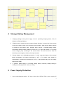
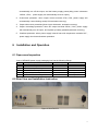
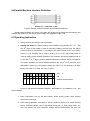
HZ4825BS Communication Power Supply
User Manual
1
Tables
1 Overview……………………………………………………………………..1
2 Main Technical Index……… ………………………………………………..1
3 System Principle Introduction………………………………………………..2
4 Battery Management……………………………
………………..3
5 Power Supply Protection……………………………………………………..3
6 Installation and Operation……………………………………………………4
6.1 Open-case Inspection …………………………………………………. 4
6.2Rear View and Installation Instruction………………………………….4
6.3Front Panel and Operation Instruction …………………………………5
6.4Top View Instruction …………………………………………………..7
6.5Communication Interface Definition……………………………………7
6.6Parallel Machine Interface Definition……………………………….. .. 8
6.7 Operating Instructions…………………………………………………. 8
6.7 Parallel Machine Instruction………………………………………. .… 9
7 Failure Analysis and Troubleshooting…………………………………………9
8 Notice………………………………………………………………………. 10
2
HZ4825BS Power Supply System User Manual
1
Overview
HZ4825BS Type single power supply system is the product improved on the basis of
HZ4825S Type of our company. This type of power supply retained some advantages of HZ4825S
Type single power supply system such as: adopting the most advanced and most popular
“full-bridge phase-shifted soft-switching” technology with little interference, high efficiency, and
reliability. It also has been made the following improvement: increasing power factor correction
unit(PFC), greatly reducing the pollutions of power grid; changing from the previous natural cold
way to the intelligent air-cooled way, which not only increase the reliability and reduce the weight,
but also more suitable for high temperature work and other harsh environment; therein, the speed
of fan is automatically adjusted through the power supply internal temperature and load quantity,
so that it is extended the life of fan and guarantee the normal operation of machine; it can be used
in parallel of many sets in order to achieve higher power output.
HZ4825BS Type single power supply system can be composed of uninterrupted direct
current power supply system after it is connected with a set of storage batteries with the capacity
not exceeding 100AH, when the utility power grid blackout, the power supply system can
seamlessly switch to backup power work. The internal power supply is equipped with storage
battery management system, which can intelligently charge and protect the battery. It can use
485 interface to make external communications, report the current working status, and receive
remote control commands.
2
Main Technical Index
Input Voltage
Single-phase 220Vac (187Vac ~ 242Vac, 48Hz ~ 52Hz,);
Output
Charging current 6 ± 1A and 11 ± 1A two ways( User can choose according to actual
situation);
Equalizing charging voltage -56.4V( -54.5V~-56.5V externally adjustable);
Rated voltage-52.8V (-52.5V ~-54.5V externally adjustable);
Rated current 25A;
Machine efficiency ≥ 90%;
Source effect ± 0.1%;
3
Load effect ± 0.5%;
Steady voltage precision ± 0.6%;
Peak-to-peak ripple <100mV (20M oscilloscope);
EMC:Conducted interference meet the A Degree;
Operating temperature: -5 ℃ ~ 45 ℃
Relative humidity: ≤ 93% (40 ℃)
Cooling Type Wind Cooling;
Casing Appearance 482mm×220mm×88mm
3
System Principle Introduction
Power supply system principle diagram see Figure 1.
Alternating current enters EMI filter by AC input end of power module, is converted to -52.8V
DC power supply for storage battery charging and load power supply by power factor correction
and DC/DC; power supply system provides constant-current constant-voltage charging for
storage battery, which means when storage battery is not full charged, the system uses
constant-current charging, the output voltage is converted to constant-voltage mode after
storage battery is fully charged; CPU in the system can monitor display AC input voltage, DC
output voltage, output current, charging current. 485 interface and external communications
report the current working status and receive commands.
1、 Power supply system can be connected with a set of storage batteries with capacity not
exceeding 100AH.
2、Adopt CPU digital display voltage and current. Both CPU and hardware inspect the limit value
of voltage and current, it alarms if exceeding limit value. Hardware controls charging and main
and backup power switching to ensure that CPU does not affect power supply system circuit
operation when interrupted.
3、 When AC utility power and power supply are in normal operating conditions, power supply
charge for storage battery and supply electricity for output load; when AC power-down or
power converter break down, backup storage battery power supply automatically import for
output load power supply. Main power and backup power truly realize seamless switching.
4、 Backup power circuit with 30A tandem connection can replace fuse. When backup circuit
current exceeds its rated value or short-circuit, the fuse is burn down to ensure the safety of
storage battery.
4
Figure 1 Composition Diagram
4
Storage Battery Management
1.
Charging settings: when power supply is set in equalizing charging status, 10h±1h
changes to floating charging;
2.
Charging ways: constant-current constant-voltage charging. It means that when storage
is not fully charged, system uses constant-current charging, when storage battery voltage
is charged to the setting value, charging ways convert to constant-voltage mode;
conventional storage battery charging current is 6±1A, users can choose 11±1A large
current charging way according to the actual needs. The rated current is 25A, the
remaining current supply to load by the output terminal.
3.
Storage battery over discharging protection: in order to protect battery, when storage
battery discharges, the battery discharges to 45V ± 1V, system alarm battery is
undervoltage, it continues to discharge to 42.5V±1V and protect relay turns off, battery
stops power supply.
4.
In general, power supply is in floating charge status, ex-factory voltage setting is
-52.8V(user can adjust from -52.5V to -54.5V) .
5
Power Supply Protection
1.
Input undervoltage protection: AC input is less than 185Vac±5Vac, power supply will
5
automatically turn off the output, and the battery supply power(utility power is between
190Vac±5Vac, power supply can automatically recover output);
2.
Overcurrent protection: when output current exceeds 27A±0.5A, power supply will
automatically current-limiting work(≤ 25A automatic recovery);
3.
Output short-circuit protection((short-circuit elimination, automatic recovery);
4.
Output overvoltage protection: when DC output exceeds 59Vdc±1Vdc, power supply
will automatically turn off output, and replace by battery powered(automatic recovery);
5.
Overheat protection: when power supply internal heat sink temperature exceeds 90℃,
power supply circuit start shutdown protection.
6
Installation and Operation
6.1 Open-case Inspection
A set of HZ4825S power supply packaging box has the following fittings:
No.
Name
Quantity
Remarks
1
Power Supply Machine
1
2
AC Input Line
1
3
Instruction Manual
1
4
1
30A(Battery)Fuse
5
Parallel Machine Line
2
Optional
6
Parallel Machine Signal Line
1
Optional
6.2 Rear View and Installation Instruction
Figure 2 Rear Panel a
6
CON2
CON3
K1:
AC input
port
F1
CON1
Figure 3 Rear Panel b
Ground point
Figure 4 Rear Panel c
1. K1 is AC input port, utility power enters power supply by this port.
2. CON1 is DC output and battery input end. Output + is connected with load positive,
output – is connected with load negative, battery + is connected with battery
positive, battery – is connected with battery negative. Pay attention to the positive
pole and negative pole when connecting.
3. F1 is battery fuse: the rated current is 30 A, when battery circuit is overcurrent or
short-circuits, the fuse burns down to protect battery.
4. CON2 is 485 communication port, this port ca communicate this power supply with
outside. CON3 is parallel machine port.
5. PE is case grounded bolt, which must be grounded reliably.
6.3 Front Panel and Operation Instruction
F
igure 5 Front Panel a
7
Figure 6 Front Panel b
6.3.1 POWER AC Input Switch
6.3.2 Indicator Light:
1. IN AC power supply failure: when AC power supply breaks down, the indicator light (red)
flashes and accompanied by buzzer call; otherwise the indicator light is off.
2. OUT output failure: when DC output power supply breaks down, the indicator light (red)
flashes and accompanied by buzzer call; otherwise the indicator light is off.
3. BAT battery failure: when battery breaks down, the indicator light (red) flashes and
accompanied by buzzer call; otherwise the indicator light is off
4. SET equalizing and float charging setting indicator light: when press the SET button, the
green light indicates the current LED display is float voltage setting value; the red light
indicates the current LED display is equalizing voltage setting value;
5. JF equalizing and float charging indicator light: the red indicates battery is in equalizing
charging status, the green indicates battery is in float charging status.
6. VO display output voltage indicator light: when this light is on, it indicates that the
current display is output voltage.
7. VI display input voltage indicator light; when this light is on, it indicates the current
display is input voltage.
8. IO display output voltage indicator light; when this light is on, it indicates the current
display is output voltage.
9. IB display battery charging and discharging current indicator light; when this light is on,
it indicates the current display is battery charging and discharging current.
6.3.2 Keys:
8
1.V/I output switch: manual operation, can be recycled to switch output voltage, input
voltage, output current, battery current display; this key can also be failure mute
button, if there is no new failure, it will permanently be mute. This key automatically
returns to output voltage display after few seconds.
2.SET equalizing and float charging voltage setting switch: manual operation, can be
recycled to switch float charging setting value, equalizing charging voltage setting value,
this key automatically returns to output voltage display after few seconds.
3.+ set for equalizing and float charging voltage parameters.
4. - set for equalizing and float charging voltage parameters.
5. JF equalizing and float charging switch: manual operation, can be forced switch equalizing
and float status.
6.4 Top View Instruction
Figure 7 Top View a
Figure 8 Top View b
One dialup switch: can switch the charging current of this machine, and set 485 port of this
machine address in communication, see 6.7 for detail.
9
6.5 Communication Interface Definition
Figure 9 Communication Port
As seen here,the left is communication port, the right is parallel machine port.
Figure 10 Communication Interface Definition Diagram
通信专用接线:Communication special wiring
Pin No.
2
3
9
Signal Definition
R/T+
R/TGND
Cable monitor should use twisted pair, and must ensure R/T+ and R/Tcorresponds to a pair of twisted pair, GND is ground connected with communication
equipment signal, otherwise it will affect the transmission distance of signal; the cable
length should be limited within 1000 m.
10
6.6Parallel Machine Interface Definition
Figure11 Parallel machine interface and parallel line definition
Signal parallel machine line uses 9 core cable, the length can be determined according to the
position and distance of two sets of power supply, the suggested length <1M.
6.7Operating Instruction
1. Wiring correctly according to the requirement;
2. Setting dial status: the factory setting of dial switches are generally OFF(0), and
the 10th digit of dial switch is used for choosing charging current level, the switch
turned to ON is for low current 6±1A charging, the switch turned to OFF is for heavy
current 11±1A charging; the 9th digit is vacancy; the 1st to 8th digit of dial switch is
used for setting communication address of this machine (the factory address sets as
0, and the 1st to 3rd digit is product address expansion positions, which is invalid for
user when operation, the actual address positions are only 4th to 8th positions, from
00010000 to 00011111), the specific setting see Figure 12: the address is 8 digits
binary, turn down is “1”(ON), turn up is “0”(OFF).。
p
p
p
p
1
2
3
4
p
p
p
p
p
Null
5
6
7
8
9
OFF
ON
1
0
1
Address Code Position
0
Figure 12 Dial Switch Schematic Diagram:00010000=16(the address is 16);low
current charge
3. After confirmation, turn on AC input switch, power supply system enter working
status after 5 seconds;
4. After starting operation, according to actual conditions, press JF to switch working
status; ex-factory default value is equalizing charge 56.4 V, float charge 52.8V, the
user can directly use, don’t arbitrarily change without professionals; the user can
11
press V/I to see power supply output voltage, input voltage, output current and
battery charge and discharge current value in turn; the users can also press SET to
see each parameter setting value; LED display unit: voltage-Volt, current- Amp;
5. When it break down, the buzzer makes continuous alarm sound, the indicator light
related to the failure will turn to red and flash to report the failure position for the user,
the alarm stops when it returns to normal; press V/I to erasure the sound of buzzer,
the buzzer re-alarms when new failure appears, if there is no new failure, the buzzer
will be permanently mute.
6. When sending a set of 485 port equalizing and float charging command or in enquiry
status, please set the communication address first, and ensure that the
communication line is connected correctly, and make sure communication is normal;
7. The case PE is PGND, which should be reliably connected with machine room as
required.
8. The biggest capacity of backup battery of this power supply is 100AH.
9. When you use HZ4825BS power supply in parallel, please be sure to counted
the “output” end of each power supply according to the ways of “+”with “+”,
“-”with “-”
, the connection line can not less than 2.5 squares, which should
be as short as possible. Parallel connect the parallel machine line, and make
several set of power supplies work on load together.
6.8Parallel Machine Instruction
When two or more than two sets of HZ4825BS are used in parallel, the maximum output
current is N×25A(N means the number of machines in parallel ); the battery charging current is
the sum of each machine’s setting current, (I=I1+I2+I3……,I is the total charging current, I1、I2、
I3…… is each machine’s charging current).
7Failure Analysis and Troubleshooting
HZ4825BS power supply has the functions of alarming and monitoring, except for reporting
information by communication and be monitored, the device itself also provide every kind of
warning lights, and make alarm bell sound until troubleshooting. Before troubleshooting, the alarm
bell can be shut down by key.
1. If it does not work after starting up, check whether the utility power voltage is higher or
lower than power supply rated input voltage range first
2. If power supply can not charge for battery, or battery can not supply power for
equipment, open the output fuse of output end, if the fuse burns down, change it;
12
check whether the electrical machine short circuit or transient short-circuit.
3. When IN indicator light flashes, and the bell rings, the utility power probably has been
off; or probably the utility power is lower than 185±5Vac ; or probably inside of the
module break down, the power supply can not output current.
4. When OUT indicator light flashes and the bell rings, the whole power supply system
break down. The output current probably make overcurrent protection; or probably the
output voltage is drop off; or probably the main power break down, storage battery
over discharge during power supply.
5. When BAT indicator light flashes, and the bell rings, the battery probably over
discharge, the voltage is lower than 44V, long time over discharge will damage the
battery; or it probably does not access to the batter; or probably the fuse burns down.
8 Notice:
● When single power supply works in the best conditions, it is suggested to choose battery with
capacity less than 100AH ;
● The batteries can be connected when start up, the method is the power supply is set as
float charge first, remove the battery fuse and connect battery cable, ensure the
battery + pole and – poles correspond to the battery connection side of power supply,
and then reinstall the fuse.
● When installation, maintain ventilation to ensure the air in power supply flows smoothly.
● When wiring, pay attention to the connection positions, prevent from misconnection causing
machine damage and personal injury.
● When wiring, connect firmly and avoid virtual connection.
● When HZ4825BS is in normal operation, the case should be reliable grounding (PE) as
required, and the communication equipment connected with it should be common-base
linked.
● Our company is responsible for product maintenance, connect us if there is any problems, user
can not open cover to make repairs, otherwise bear your own consequences if there is any
personal safety problem.
13


![[输入书名]](http://vs1.manualzilla.com/store/data/005783394_1-fc20c72617a19a0d7587a472ef1576a7-150x150.png)