1
99 Washington Street
Melrose, MA 02176
Phone 781-665-1400
Toll Free 1-800-517-8431
www.keithley.com
Visit us at www.TestEquipmentDepot.com
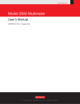
Model 2000 Multimeter
User’s Manual
2000-900-01 Rev. J / August 2010
A
G R E A T E R
M E A S U R E
O F
C O N F I D E N C E
2000-900 (J - Aug 2010) BOOK.fm Page 1 Wednesday, October 12, 2011 12:29 PM
Model 2000 Multimeter
User’s Manual
©1994-2010, Keithley Instruments, Inc.
All rights reserved.
Cleveland, Ohio, U.S.A.
Document Number: 2000-900-01 Rev. J / August 2010
Test Equipment Depot - 800.517.8431 - 99 Washington Street Melrose, MA 02176
TestEquipmentDepot.com
2000-900 (J - Aug 2010) BOOK.fm Page 2 Wednesday, October 12, 2011 12:29 PM
Test Equipment Depot - 800.517.8431 - 99 Washington Street Melrose, MA 02176
TestEquipmentDepot.com
2000-900 (J - Aug 2010) BOOK.fm Page 1 Wednesday, October 12, 2011 12:29 PM
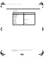
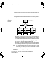
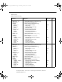
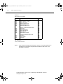
Table of Contents
1 General Information
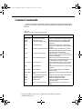
Feature overview..................................................................................1-2
Manual addenda ..................................................................................1-3
Safety symbols and terms ....................................................................1-3
Specifications .......................................................................................1-3
Inspections ...........................................................................................1-4
Options and accessories ......................................................................1-5
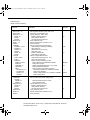
2 Basic Measurements
Introduction ..........................................................................................2-2
Front panel summary ...........................................................................2-3
Rear panel summary ............................................................................2-6
Power-up ..............................................................................................2-8
Display ...............................................................................................2-17
Measuring voltage ..............................................................................2-18
Measuring current ..............................................................................2-22
Measuring resistance .........................................................................2-24
Measuring frequency and period........................................................2-26
Measuring temperature ......................................................................2-28
Math ...................................................................................................2-30
Measuring continuity ..........................................................................2-34
Testing diodes ....................................................................................2-35
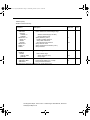
3 Measurement Options
Introduction ..........................................................................................3-2
Measurement configuration..................................................................3-3
Trigger operations ................................................................................3-8
Buffer operations ................................................................................3-17
Limit operations ..................................................................................3-20
Scan operations .................................................................................3-22
System operations .............................................................................3-32
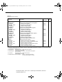
4 Remote Operation
Introduction ..........................................................................................4-2
Selecting a language............................................................................4-4
RS-232 operation .................................................................................4-6
GPIB bus operation and reference.......................................................4-9
Status structure ..................................................................................4-19
Trigger model (GPIB operation) .........................................................4-29
Programming syntax ..........................................................................4-32
Common commands ..........................................................................4-39
5 SCPI Command Reference
SCPI Signal oriented measurement commands ..................................5-3
SCPI command subsystems reference tables .....................................5-7
Calculate subsystem ..........................................................................5-20
DISPlay subsystem ............................................................................5-26
:FORMat subsystem ..........................................................................5-28
ROUTe subsystem .............................................................................5-32
[SENSe[1]] subsystem .......................................................................5-37
Test Equipment Depot - 800.517.8431 - 99 Washington Street Melrose, MA 02176
TestEquipmentDepot.com
2000-900 (J - Aug 2010) BOOK.fm Page 2 Wednesday, October 12, 2011 12:29 PM
STATus subsystem ............................................................................ 5-52
:SYSTem subsystem.......................................................................... 5-61
:TRACe subsystem ............................................................................ 5-68
Trigger subsystem ............................................................................. 5-70
:UNIT subsystem ............................................................................... 5-74
B Status and Error Messages
C Example Programs
Program examples...............................................................................C-2
D Models 196/199 and 8840A/8842A Commands
E IEEE-488 Bus Overview
Introduction ..........................................................................................E-2
Bus description ....................................................................................E-4
Bus lines ..............................................................................................E-6
Bus commands ....................................................................................E-8
Interface function codes.....................................................................E-15
F IEEE-488 and SCPI Conformance Information
Introduction .......................................................................................... F-2
Test Equipment Depot - 800.517.8431 - 99 Washington Street Melrose, MA 02176
TestEquipmentDepot.com
2000-900 (J - Aug 2010) BOOK.fm Page 1 Wednesday, October 12, 2011 12:29 PM
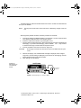
1
General
Information
Test Equipment Depot - 800.517.8431 - 99 Washington Street Melrose, MA 02176
TestEquipmentDepot.com
2000-900 (J - Aug 2010) BOOK.fm Page 2 Wednesday, October 12, 2011 12:29 PM
1-2
General Information
Introduction
This section contains general information about the Model 2000 Multimeter. The information is organized as follows:
•
•
•
•
•
•
Feature overview
Manual addenda
Safety symbols and terms
Specifications
Inspection
Options and accessories
If you have any questions after reviewing this information, please contact your local
Keithley representative or call one of our Applications Engineers at 1-800-348-3735 (U.S.
and Canada only). Worldwide phone numbers are listed at the front of this manual.
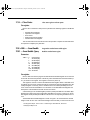
Feature overview
The Model 2000 is a 6½-digit high-performance digital multimeter. It has 0.002% 90-day
basic DC voltage accuracy and 0.008% 90-day basic resistance accuracy. At 6½ digits, the
multimeter delivers 50 triggered readings/sec over the IEEE-488 bus. At 4½ digits, it can
read up to 2000 readings/sec into its internal buffer. The Model 2000 has broad measurement ranges:
•
•
•
•
•
•
•
DC voltage from 0.1μV to 1000V.
AC (RMS) voltage from 0.1μV to 750V, 1000V peak.
DC current from 10nA to 3A.
AC (RMS) current from 1μA to 3A.
Two and four-wire resistance from 100µΩ to 120MΩ.
Frequency from 3Hz to 500kHz.
Thermocouple temperature from -200°C to +1372°C.
Some additional capabilities of the Model 2000 include:
•
•
•
•
•
Full range of functions — In addition to those listed above, the Model 2000 functions
include period, dB, dBm, continuity, diode testing, mX+b, and percent.
Optional scanning — For internal scanning, options include the Model 2000-SCAN,
a 10-channel, general-purpose card, and the Model 2001-TCSCAN, a 9-channel,
thermocouple card with a built-in cold junction. For external scanning, the Model
2000 is compatible with Keithley's Model 7001 and 7002 switch matrices and cards.
Programming languages and remote interfaces — The Model 2000 offers three programming language choices (SCPI, Keithley Models 196/199, and Fluke 8840A/
8842A) and two remote interface ports (IEEE-488/GPIB and RS-232C).
Reading and setup storage — Up to 1024 readings and two setups (user and factory
defaults) can be stored and recalled.
Closed-cover calibration — The instrument can be calibrated either from the front
panel or remote interface.
Test Equipment Depot - 800.517.8431 - 99 Washington Street Melrose, MA 02176
TestEquipmentDepot.com
2000-900 (J - Aug 2010) BOOK.fm Page 3 Wednesday, October 12, 2011 12:29 PM
1-3
Manual addenda
Any improvements or changes concerning the instrument or manual will be explained in
an addendum included with the manual. Be sure to note these changes and incorporate
them into the manual.
Safety symbols and terms
The following symbols and terms may be found on the instrument or used in this manual.
The ! symbol on the instrument indicates that the user should refer to the operating
instructions located in the manual.
The
symbol on the instrument shows that high voltage may be present on the terminal(s). Use standard safety precautions to avoid personal contact with these voltages.
The WARNING heading used in this manual explains dangers that might result in personal injury or death. Always read the associated information very carefully before performing the indicated procedure.
The CAUTION heading used in this manual explains hazards that could damage the instrument. Such damage may invalidate the warranty.
Test Equipment Depot - 800.517.8431 - 99 Washington Street Melrose, MA 02176
TestEquipmentDepot.com
2000-900 (J - Aug 2010) BOOK.fm Page 4 Wednesday, October 12, 2011 12:29 PM
1-4
General Information
Inspection
The Model 2000 was carefully inspected electrically and mechanically before shipment.
After unpacking all items from the shipping carton, check for any obvious signs of physical
damage that may have occurred during transit. (Note: There may be a protective film over
the display lens, which can be removed.) Report any damage to the shipping agent immediately. Save the original packing carton for possible future reshipment. The following items
are included with every Model 2000 order:
•
•
•
•
•
•
•
Model 2000 Multimeter with line cord.
Safety test leads (Model 1751).
Accessories as ordered.
Certificate of calibration.
Model 2000 User's Manual (P/N 2000-900-00).
Model 2000 Calibration Manual (P/N 2000-905-00).
Model 2000 Support Software Disk including TestPoint run-time applications,
TestPoint instrument libraries for GPIB and RS-232, and QuickBASIC examples.
If an additional manual is required, order the appropriate manual package. The manual
packages include a manual and any pertinent addenda.
Test Equipment Depot - 800.517.8431 - 99 Washington Street Melrose, MA 02176
TestEquipmentDepot.com
2000-900 (J - Aug 2010) BOOK.fm Page 5 Wednesday, October 12, 2011 12:29 PM
1-5
Options and accessories
The following options and accessories are available from Keithley for use with the Model
2000.
Scanner cards
Model 2000-SCAN: This is a 10-channel scanner card that installs in the option slot of the
Model 2000. Channels can be configured for 2-pole or 4-pole operation. Included are two
pairs of leads for connection to Model 2000 rear panel inputs (Keithley P/N CA-109).
Model 2001-TCSCAN: This is a thermocouple scanner card that installs in the option slot
of the Model 2000. The card has nine analog input channels that can be used for high-accuracy, high-speed scanning. A built-in temperature reference allows multi-channel, coldjunction compensated temperature measurements using thermocouples.
General purpose probes
Model 1754 Universal Test Lead Kit: Consists of one set of test leads (0.9m), two spade
lugs, two banana plugs, two hooks, and two alligator clips.
Model 8605 High Performance Modular Test Leads: Consists of two high voltage (1000V)
test probes and leads. The test leads are terminated with a banana plug with retractable
sheath on each end.
Model 8606 High Performance Probe Tip Kit: Consists of two spade lugs, two alligator
clips, and two spring hook test probes. (The spade lugs and alligator clips are rated at 30V
RMS, 42.4V peak; the test probes are rated at 1000V.) These components are for use with
high performance test leads terminated with banana plugs, such as the Model 8605.
The following test leads and probes are rated at 30V RMS, 42.4V peak:
Models 5805 and 5805-12 Kelvin Probes: Consists of two spring-loaded Kelvin test
probes with banana plug termination. Designed for instruments that measure 4-terminal
resistance. The Model 5805 is 0.9m long; the Model 5805-12 is 3.6m long.
Model 5806 Kelvin Clip Lead Set: Includes two Kelvin clip test leads (0.9m) with banana
plug termination. Designed for instruments that measure 4-terminal resistance. A set of eight
replacement rubber bands is available as Keithley P/N GA-22.
Model 8604 SMD Probe Set: Consists of two test leads (0.9m), each terminated with a
surface mount device “grabber” clip on one end and a banana plug with a retractable sheath
on the other end.
Low thermal probes
Model 8610 Low Thermal Shorting Plug: Consists of four banana plugs mounted to a 1inch square circuit board, interconnected to provide a short circuit among all plugs.
Test Equipment Depot - 800.517.8431 - 99 Washington Street Melrose, MA 02176
TestEquipmentDepot.com
2000-900 (J - Aug 2010) BOOK.fm Page 6 Wednesday, October 12, 2011 12:29 PM
1-6
General Information
Model 8611 Low Thermal Patch Leads: Consists of two test leads (0.9m), each with a
banana plug with a retractable sheath at each end. These leads minimize the thermallyinduced offsets that can be created by test leads.
Model 8612 Low Thermal Spade Leads: Consists of two test leads (0.9m), each terminated with a spade lug on one end and a banana plug with a retractable sheath on the other
end. These leads minimize the thermally-induced offsets that can be created by test leads.
Cables and adapters
Models 7007-1 and 7007-2 Shielded GPIB Cables: Connect the Model 2000 to the GPIB
bus using shielded cables and connectors to reduce electromagnetic interference (EMI).
The Model 7007-1 is 1m long; the Model 7007-2 is 2m long.
Models 8501-1 and 8501-2 Trigger Link Cables: Connect the Model 2000 to other instruments with Trigger Link connectors (e.g., Model 7001 Switch System). The Model 8501-1 is
1m long; the Model 8501-2 is 2m long.
Model 8502 Trigger Link Adapter: Allows you to connect any of the six Trigger Link lines
of the Model 2000 to instruments that use the standard BNC trigger connectors.
Model 8504 DIN to BNC Trigger Cable: Allows you to connect Trigger Link lines one (Voltmeter Complete) and two (External Trigger) of the Model 2000 to instruments that use BNC
trigger connectors. The Model 8504 is 1m long.
Rack mount kits
Model 4288-1 Single Fixed Rack Mount Kit: Mounts a single Model 2000 in a standard
19-inch rack.
Model 4288-2 Side-by-Side Rack Mount Kit: Mounts two instruments (Models 182, 428,
486, 487, 2000, 2001, 2002, 6517, 7001) side-by-side in a standard 19-inch rack.
Model 4288-3 Side-by-Side Rack Mount Kit: Mounts a Model 2000 and a Model 199 sideby-side in a standard 19-inch rack.
Model 4288-4 Side-by-Side Rack Mount Kit: Mounts a Model 2000 and a 5.25-inch instrument (Models 195A, 196, 220, 224, 230, 263, 595, 614, 617, 705, 740, 775, etc.) side-byside in a standard 19-inch rack.
Carrying case
Model 1050 Padded Carrying Case: A carrying case for a Model 2000. Includes handles
and shoulder strap.
Test Equipment Depot - 800.517.8431 - 99 Washington Street Melrose, MA 02176
TestEquipmentDepot.com
2000-900 (J - Aug 2010) BOOK.fm Page 1 Wednesday, October 12, 2011 12:29 PM
2
Basic
Measurements
Test Equipment Depot - 800.517.8431 - 99 Washington Street Melrose, MA 02176
TestEquipmentDepot.com
2000-900 (J - Aug 2010) BOOK.fm Page 2 Wednesday, October 12, 2011 12:29 PM
Basic Measurements
This section summarizes front panel operation of the Model 2000. It is organized as follows:
•
•
•
•
•
•
•
•
•
•
•
•
Front panel summary — Includes an illustration and summarizes keys, display, and
connections.
Rear panel summary — Includes an illustration and summarizes connections.
Power-up — Describes connecting the instrument to line power, the power-up sequence, the warm-up time, and default conditions.
Display — Discusses the display format and messages that may appear while using
the instrument.
Measuring voltage — Covers DC and AC voltage measurement connections and low
level voltage considerations.
Measuring current — Covers DC and AC current measurement connections and current fuse replacement.
Measuring resistance — Details two and four-wire measurement connections and
shielding considerations.
Measuring frequency and period — Covers frequency and period measurement connections.
Measuring temperature — Describes the use of thermocouples for temperature measurements.
Math — Covers the mX+b, percent, dBm, and dB math functions performed on single
readings.
Measuring continuity — Explains setting up and measuring continuity of a circuit.
Testing diodes — Describes testing general-purpose and zener diodes.
Test Equipment Depot - 800.517.8431 - 99 Washington Street Melrose, MA 02176
TestEquipmentDepot.com
2000-900 (J - Aug 2010) BOOK.fm Page 3 Wednesday, October 12, 2011 12:29 PM
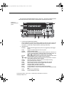
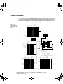
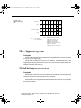
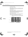
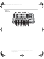
The front panel of the Model 2000 is shown in Figure 2-1. This figure includes important
abbreviated information that should be reviewed before operating the instrument.
Figure 2-1
Model 2000 front
panel
SENSE
Ω 4 WIRE
6
INPUT
HI
STEP SCAN CH1
REM
TALK
LSTN
SRQ
SHIFT
TIMER HOLD TRIG
FAST
5
CH2
MED
CH3
SLOW
CH4
CH5
REL
FILT
CH6
AUTO
CH7
CH8
ERR
CH10 MATH
REAR
CH9
BUFFER
STAT
350V
PEAK
4W
1000V
PEAK
!
2000 MULTIMETER
1
3
SHIFT
MX+B
%
dBm
dB
CONT
DCV
ACV
DCI
ACI
Ω2
DELAY
LOCAL
POWER
HOLD
EX TRIG TRIG
SAVE
SETUP
OPEN CLOSE
LIMITS
ON/OFF
TEST
STORE RECALL
CONFIG
HALT
STEP
SCAN
Ω4
FREQ
500V
PEAK
INPUTS
TEMP
RANGE
F
R
CAL
FILTER
REL
GPIB
RS232
AUTO
FRONT/REAR
3A 250V
AMPS
RANGE
EXIT
DIGITS RATE
2
LO
PERIOD TCOUPL
8
ENTER
4
7
1
Function keys (shifted and unshifted)
Select measurement function (DC and AC voltage, DC and AC current, 2-wire and
4-wire resistance, frequency, period, temperature with thermocouples), math function (mX+b, %, dBm, dB), or special function (continuity, diode test).
2
Operation keys
EXTRIG
Selects external triggers (front panel, bus, trigger link) as the trigger
source.
TRIG
Triggers a measurement from the front panel.
STORE
Enables reading storage.
RECALL
Displays stored readings and buffer statistics (maximum, minimum, average, standard deviation). Use ▲ and ▼ to scroll through buffer; use
and
to toggle between reading number and reading.
FILTER
Displays digital filter status for present function and toggles filter on/off.
REL
Enables/disables relative reading on present function.
and
Moves through selections within functions and operations. If scanner
card installed, manually scans channels.
OPEN
Opens all channels on internal scanner card; stops scanning.
CLOSE
Closes selected internal channel.
STEP
Steps through channels; sends a trigger after each channel.
SCAN
Scans through channels; sends a trigger after last channel.
DIGITS
Changes number of digits of resolution.
RATE
Changes reading rate: fast, medium, slow.
EXIT
Cancels selection, moves back to measurement display.
ENTER
Accepts selection, moves to next choice or back to measurement display.
SHIFT
Used to access shifted keys.
LOCAL
Cancels GPIB remote mode.
Test Equipment Depot - 800.517.8431 - 99 Washington Street Melrose, MA 02176
TestEquipmentDepot.com
2000-900 (J - Aug 2010) BOOK.fm Page 4 Wednesday, October 12, 2011 12:29 PM
3
Shifted operation keys
DELAY
Sets user delay between trigger and measurement.
HOLD
Holds reading when the selected number of samples is within the selected
tolerance.
LIMITS
Sets upper and lower limit values for readings.
ON/OFF
Enables/disables limits; selects beeper operation for limit testing.
TEST
Selects built-in tests, diagnostics, display test.
CAL
Accesses calibration.
SAVE
Saves present configuration for power-on user default.
SETUP
Restores factory or user default configuration.
CONFIG
Selects minimum/maximum channels, timer, and reading count for step/
scan.
HALT
Turns off step/scan.
GPIB
Enables/disables GPIB interface; selects address and language.
RS232
Enables/disables RS-232 interface; selects baud rate, flow control, terminator.
4
Range keys
AUTO
5
Annunciators
*(asterisk)
(diode)
))) (speaker)
(more)
4W
AUTO
BUFFER
CH 1-10
ERR
FAST
FILT
HOLD
LSTN
MATH
MED
REAR
REL
REM
SCAN
SHIFT
SLOW
SRQ
STAT
STEP
TALK
TIMER
TRIG
Moves to higher range; increments digit; moves to next selection.
Moves to lower range; decrements digit; moves to previous selection.
Enables/disables autorange.
Reading being stored.
Instrument is in diode testing function.
Beeper on for continuity or limits testing.
Indicates additional selections are available.
4-wire resistance reading displayed.
Autoranging enabled.
Recalling stored readings.
Displayed internal channel is closed.
Questionable reading; invalid cal step.
Fast reading rate.
Digital filter enabled.
Instrument is in hold mode.
Instrument addressed to listen over GPIB.
Math function (mX+b, %, dB, dBm) enabled.
Medium reading rate.
Reading acquired from rear inputs.
Relative reading displayed.
Instrument is in GPIB remote mode.
Instrument is in scan mode.
Accessing shifted keys.
Slow reading rate.
Service request over GPIB.
Displaying buffer statistics.
Instrument is in step mode.
Instrument addressed to talk over GPIB.
Timed scans in use.
Indicates external trigger (front panel, bus, trigger link) selected.
Test Equipment Depot - 800.517.8431 - 99 Washington Street Melrose, MA 02176
TestEquipmentDepot.com
2000-900 (J - Aug 2010) BOOK.fm Page 5 Wednesday, October 12, 2011 12:29 PM
6
Input connections
INPUT HI and LO
AMPS
SENSE Ω4 WIRE
HI and LO
Used for making DC volts, AC volts, 2-wire resistance measurements.
Used in conjunction with INPUT LO to make DC current and AC
current measurements. Also holds current input fuse (3A, 250V,
fast blow, 5×20mm).
Used with INPUT HI and LO to make 4-wire resistance measurements.
7
INPUTS
Selects input connections on front or rear panel.
8
Handle
Pull out and rotate to desired position.
Test Equipment Depot - 800.517.8431 - 99 Washington Street Melrose, MA 02176
TestEquipmentDepot.com
2000-900 (J - Aug 2010) BOOK.fm Page 6 Wednesday, October 12, 2011 12:29 PM
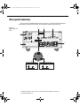
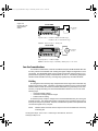
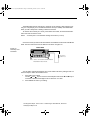
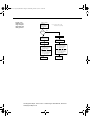
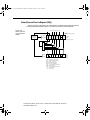
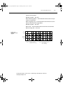
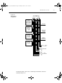
Rear panel summary
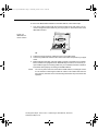
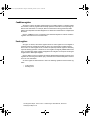
The rear panel of the Model 2000 is shown in Figure 2-2. This figure includes important
abbreviated information that should be reviewed before operating the instrument.
Figure 2-2
Model 2000 rear
panel
3
4
5
WARNING:NO INTERNAL OPERATOR SERVICABLE PARTS,SERVICE BY QUALIFIED PERSONNEL ONLY.
HI
MADE IN
2
U.S.A.
IEEE-488
350V
PEAK
!
1000V
PEAK
(CHANGE IEEE ADDRESS
FROM FRONT PANEL)
TRIGGER
LINK
RS232
!
LO
SENSE
Ω 4W
500V
INPUT PEAK
3
4
1
2
5
6
VMC
EXT TRIG
!
!
LINE
250mAT
(SB)
100 VAC
120 VAC
125mAT
(SB)
220 VAC
240 VAC
LINE RATING
120
1
FUSE
50, 60
400HZ
17 VA MAX
CAUTION:FOR CONTINUED PROTECTION AGAINST FIRE HAZARD,REPLACE FUSE WITH SAME TYPE AND RATING.
8
4
5
2
3
1
#1
#2
EXTERNAL TRIGGER INPUT
Trigger Reading
TTL HI
>72μsec
6
7
TTL LO
VOLT METER COMPLETE OUTPUT
Reading
Complete
>10μsec
TTL HI
TTL LO
Test Equipment Depot - 800.517.8431 - 99 Washington Street Melrose, MA 02176
TestEquipmentDepot.com
6
2000-900 (J - Aug 2010) BOOK.fm Page 7 Wednesday, October 12, 2011 12:29 PM
2-7
1
Option slot
An optional scanner card (Model 2000-SCAN, 2001-SCAN, or 2001-TCSCAN) installs in this slot.
2
Input connections
INPUT HI and LO Used for making DC volts, AC volts, 2-wire resistance measurements and for connecting scanner card.
SENSE Ω4 WIRE Used with INPUT HI and LO to make 4-wire resistance measurements
HI and LO
and also for connecting scanner card.
3
TRIGGER LINK
One 8-pin micro-DIN connector for sending and receiving trigger pulses among other
instruments. Use a trigger link cable or adapter, such as Models 8501-1, 8501-2,
8502, 8504.
4
RS-232
Connector for RS-232 operation. Use a straight-through (not null modem) DB-9 cable.
5
IEEE-488
Connector for IEEE-488 (GPIB) operation. Use a shielded cable, such as Models
7007-1 and 7007-2.
6
Power module
Contains the AC line receptacle, power line fuse, and line voltage setting. The Model
2000 can be configured for line voltages of 100V/120V/220V/240VAC at line frequencies of 45Hz to 66Hz or 360Hz to 440Hz.
Test Equipment Depot - 800.517.8431 - 99 Washington Street Melrose, MA 02176
TestEquipmentDepot.com
2000-900 (J - Aug 2010) BOOK.fm Page 8 Wednesday, October 12, 2011 12:29 PM
2-8
Basic Measurements
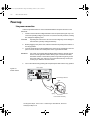
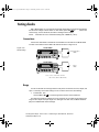
Power-up
Line power connection
Follow the procedure below to connect the Model 2000 to line power and turn on the
instrument.
1.
Check to see that the line voltage selected on the rear panel (see Figure 2-3) is correct for the operating voltage in your area. If not, refer to the next procedure, “Setting
line voltage and replacing fuse.”
CAUTION
2.
3.
Operating the instrument on an incorrect line voltage may cause damage to
the instrument, possibly voiding the warranty.
Before plugging in the power cord, make sure that the front panel power switch is in
the off (0) position.
Connect the female end of the supplied power cord to the AC receptacle on the rear
panel. Connect the other end of the power cord to a grounded AC outlet.
WARNING
4.
The power cord supplied with the Model 2000 contains a separate ground
wire for use with grounded outlets. When proper connections are made,
instrument chassis is connected to power line ground through the ground
wire in the power cord. Failure to use a grounded outlet may result in personal injury or death due to electric shock.
Turn on the instrument by pressing the front panel power switch to the on (1) position.
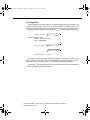
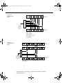
Model 2000
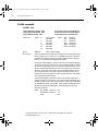
Figure 2-3
Power module
WARNING:NO INTERNAL OPERATOR SERVICABLE PARTS,SERVICE BY QUALIFIED PERSONNEL ONLY.
HI
MADE IN
U.S.A.
IEEE-488
350V
PEAK
!
1000V
PEAK
(CHANGE IEEE ADDRESS
FROM FRONT PANEL)
TRIGGER
LINK
RS232
!
LO
SENSE
Ω 4W
500V
INPUT PEAK
1
2
3
4
5
6
VMC
EXT TRIG
!
FUSE
LINE
250mAT
(SB)
100 VAC
120 VAC
125mAT
(SB)
220 VAC
240 VAC
LINE RATING
120
!
50, 60
400HZ
17 VA MAX
Line Voltage Selector
CAUTION:FOR CONTINUED PROTECTION AGAINST FIRE HAZARD,REPLACE FUSE WITH SAME TYPE AND RATING.
Fuse
100
220
240
120
Spring
Window
Fuse Holder Assembly
Test Equipment Depot - 800.517.8431 - 99 Washington Street Melrose, MA 02176
TestEquipmentDepot.com
2000-900 (J - Aug 2010) BOOK.fm Page 9 Wednesday, October 12, 2011 12:29 PM
2-9
Setting line voltage and replacing fuse
A rear panel fuse located next to the AC receptacle protects the power line input of the
instrument. If the line voltage setting needs to be changed or the line fuse needs to be replaced, perform the following steps.
WARNING
1.
2.
Place the tip of a flat-blade screwdriver into the power module by the fuse holder assembly (see Figure 2-3). Gently push in and to the left. Release pressure on the assembly and its internal spring will push it out of the power module.
Remove the fuse and replace it with the type listed in Table 2-1.
CAUTION
3.
4.
Make sure the instrument is disconnected from the AC line and other equipment before changing the line voltage setting or replacing the line fuse.
For continued protection against fire or instrument damage, only replace
fuse with the type and rating listed. If the instrument repeatedly blows fuses,
locate and correct the cause of the trouble before replacing the fuse. See the
optional Model 2000 Repair Manual for troubleshooting information.
If configuring the instrument for a different line voltage, remove the line voltage selector from the assembly and rotate it to the proper position. When the selector is installed into the fuse holder assembly, the correct line voltage appears inverted in the
window.
Install the fuse holder assembly into the power module by pushing it in until it locks
in place.
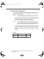
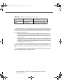
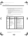
Table 2-1
Fuse ratings
Line voltage
Fuse rating
Keithley P/N
100/120V
220/240V
0.25A slow-blow 5×20mm
0.125A slow-blow 5×20mm
FU-96-4
FU-91
Test Equipment Depot - 800.517.8431 - 99 Washington Street Melrose, MA 02176
TestEquipmentDepot.com
2000-900 (J - Aug 2010) BOOK.fm Page 10 Wednesday, October 12, 2011 12:29 PM
2-10
Basic Measurements
Power-up sequence
On power-up, the Model 2000 performs self-tests on its EPROM and RAM and momentarily lights all segments and annunciators. If a failure is detected, the instrument momentarily displays an error message and the ERR annunciator turns on. (Error messages are
listed in Appendix B.)
NOTE
If a problem develops while the instrument is under warranty, return it to Keithley
Instruments, Inc., for repair.
If the instrument passes the self-tests, the firmware revision levels are displayed. An example of this display is:
REV: A01 A02
where: A01 is the main board ROM revision.
A02 is the display board ROM revision.
After the power-up sequence, the instrument begins its normal display of readings.
Test Equipment Depot - 800.517.8431 - 99 Washington Street Melrose, MA 02176
TestEquipmentDepot.com
2000-900 (J - Aug 2010) BOOK.fm Page 11 Wednesday, October 12, 2011 12:29 PM
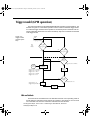
High energy circuit safety precautions
To optimize safety when measuring voltage in high energy distribution circuits, read and
use the directions in the following warning.
WARNING
Dangerous arcs of an explosive nature in a high energy circuit can cause
severe personal injury or death. If the multimeter is connected to a high
energy circuit when set to a current range, low resistance range, or any other
low impedance range, the circuit is virtually shorted. Dangerous arcing can
result even when the multimeter is set to a voltage range if the minimum voltage spacing is reduced in the external connections.
When making measurements in high energy circuits, use test leads that meet the following requirements:
•
•
•
Test leads should be fully insulated.
Only use test leads that can be connected to the circuit (e.g., alligator clips, spade
lugs, etc.) for hands-off measurements.
Do not use test leads that decrease voltage spacing. These diminishes arc protection and create a hazardous condition.
Use the following sequence when testing power circuits:
1.
2.
3.
4.
5.
6.
De-energize the circuit using the regular installed connect-disconnect device, such
as a circuit breaker, main switch, etc.
Attach the test leads to the circuit under test. Use appropriate safety rated test leads
for this application.
Set the multimeter to the proper function and range.
Energize the circuit using the installed connect-disconnect device and make measurements without disconnecting the multimeter.
De-energize the circuit using the installed connect-disconnect device.
Disconnect the test leads from the circuit under test.
WARNING
The maximum common-mode voltage (voltage between INPUT LO and the
chassis ground) is 500V peak. Exceeding this value may cause a breakdown
in insulation, creating a shock hazard.
Test Equipment Depot - 800.517.8431 - 99 Washington Street Melrose, MA 02176
TestEquipmentDepot.com
2000-900 (J - Aug 2010) BOOK.fm Page 12 Wednesday, October 12, 2011 12:29 PM
Power-on defaults
Power-on defaults are the settings the instrument assumes when it is turned on. The
Model 2000 offers two choices for the settings: factory and user. The power-on default will
be the last configuration you saved. The SAVE and SETUP keys select the two choices of
power-on defaults.
To save present configuration as user settings:
1.
2.
3.
4.
Configure the instrument as desired for USER default.
Press SHIFT then SAVE.
Use the ▲ and ▼ keys to select YES or NO.
Press ENTER.
To restore factory or user settings:
1.
2.
3.
Press SHIFT then SETUP.
Use the ▲ and ▼ keys to select FACTory or USER.
Press ENTER.
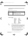
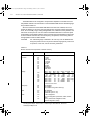
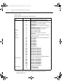
Since the basic measurement procedures in this manual assume the factory defaults, reset the instrument to the factory settings when following step-by-step procedures. Table 2-2
lists the factory default settings.
Test Equipment Depot - 800.517.8431 - 99 Washington Street Melrose, MA 02176
TestEquipmentDepot.com
2000-900 (J - Aug 2010) BOOK.fm Page 13 Wednesday, October 12, 2011 12:29 PM
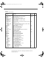
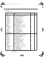
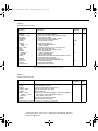
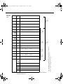
Table 2-2
Factory defaults
Setting
Factory default
Autozero
Buffer
Continuity
Beeper
Digits
Rate
Threshold
Current (AC and DC)
Digits (AC)
Digits (DC)
Filter
Count
Mode
Range
Relative
Value
Rate (AC)
Rate (DC)
Diode test
Digits
Range
Rate
Frequency and Period
Digits
Range
Relative
Value
Rate
Function
GPIB
Address
Language
Limits
Beeper
High limit
Low limit
mX+b
Scale factor
Offset
Percent
References
On
No effect
On
4½
Fast (0.1 PLC)
10Ω
5½
6½
On
10
Moving average
Auto
Off
0.0
Medium (DETector BANDwidth 30)
Medium (1 PLC)
6½
1mA
Medium (1 PLC)
6½
10V
Off
0.0
Slow (1 sec)
DCV
No effect
(16 at factory)
(SCPI at factory)
Off
Never
+1
-1
Off
1.0
0.0
Off
1.0
Test Equipment Depot - 800.517.8431 - 99 Washington Street Melrose, MA 02176
TestEquipmentDepot.com
2000-900 (J - Aug 2010) BOOK.fm Page 14 Wednesday, October 12, 2011 12:29 PM
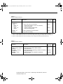
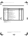
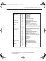
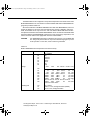
Table 2-2 (cont.)
Factory defaults
Setting
Resistance (2-wire and 4-wire)
Digits
Filter
Count
Mode
Range
Relative
Value
Rate
RS-232
Baud
Flow
Tx term
Scanning
Channels
Mode
Temperature
Digits
Filter
Count
Mode
Junction
Temperature
Relative
Value
Rate
Thermocouple
Units
Triggers
Continuous
Delay
Source
Factory default
6½
On
10
Moving average
Auto
Off
0.0
Medium (1 PLC)
Off
No effect
No effect
No effect
Off
1-10
Internal
5½
On
10
Moving average
Simulated
23°C
Off
0.0
Medium (1 PLC)
J
°C
On
Auto
Immediate
Test Equipment Depot - 800.517.8431 - 99 Washington Street Melrose, MA 02176
TestEquipmentDepot.com
2000-900 (J - Aug 2010) BOOK.fm Page 15 Wednesday, October 12, 2011 12:29 PM
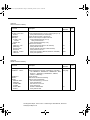
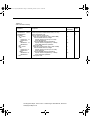
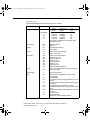
Table 2-2 (cont.)
Factory defaults
Setting
Factory default
Voltage (AC and DC)
dB reference
dBm reference
Digits (AC)
Digits (DC)
Filter
Count
Mode
Range
Relative
Value
Rate (AC)
Rate (DC)
No effect
75Ω
5½
6½
On
10
Moving average
Auto
Off
0.0
Medium*
Medium (1 PLC)
Test Equipment Depot - 800.517.8431 - 99 Washington Street Melrose, MA 02176
TestEquipmentDepot.com
2000-900 (J - Aug 2010) BOOK.fm Page 16 Wednesday, October 12, 2011 12:29 PM
GPIB primary address
The GPIB primary address of the instrument must be the same as the primary address
you specify in the controller’s programming language. The default primary address of the
instrument is 16, but you can set the address to any value from 0 to 30 by using the following
step by step instructions.
1.
2.
3.
4.
5.
Press SHIFT then GPIB.
Use the and keys to select ADDRess. Or, press ENTER. Once you have
pressed ENTER, the unit automatically displays the address selection.
Use the
and
keys to toggle from ADDRess to the numeric entry. Notice the
values are blinking.
Use the and keys to change the numeric entries to the desired address.
Press ENTER.
See Section Four — Remote Operation for more GPIB information.
Warm-up time
The Model 2000 is ready for use as soon as the power-up sequence has completed.
However, to achieve rated accuracy, allow the instrument to warm up for one hour. If the
instrument has been subjected to extreme temperatures, allow additional time for internal
temperatures to stabilize.
Test Equipment Depot - 800.517.8431 - 99 Washington Street Melrose, MA 02176
TestEquipmentDepot.com
2000-900 (J - Aug 2010) BOOK.fm Page 17 Wednesday, October 12, 2011 12:29 PM
Display
The display of the Model 2000 is primarily used to display readings, along with the units
and type of measurement. Annunciators are located on the top, bottom, right, and left of the
reading or message display. The annunciators indicate various states of operation. See Figure 2-1 for a complete listing of annunciators.
Status and error messages
Status and error messages are displayed momentarily. During Model 2000 operation and
programming, you will encounter a number of front panel messages. Typical messages are
either of status or error variety, as listed in Appendix B.
Test Equipment Depot - 800.517.8431 - 99 Washington Street Melrose, MA 02176
TestEquipmentDepot.com
2000-900 (J - Aug 2010) BOOK.fm Page 18 Wednesday, October 12, 2011 12:29 PM
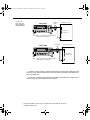
Measuring voltage
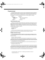
The Model 2000 can make DCV measurements from 0.1µV to 1000V and ACV measurements from 0.1µV to 750V RMS, 1000V peak.
Connections
Assuming factory default conditions, the basic procedure is as follows:
1.
2.
4.
Connect test leads to the INPUT HI and LO terminals. Either the front or rear inputs
can be used; place the INPUTS button in the appropriate position.
Select the measurement function by pressing DCV or ACV.
Pressing AUTO toggles autoranging. Notice the AUTO annunciator is displayed with
autoranging. If you want manual ranging, use the RANGE and keys to select
a measurement range consistent with the expected voltage.
Connect test leads to the source as shown in Figure 2-4.
CAUTION
5.
6.
Do not apply more than 1000V peak to the input or instrument damage may
occur. The voltage limit is subject to the 8 × 10⁷V•Hz product.
Observe the display. If the “OVERFLOW” message is displayed, select a higher
range until an o normal reading is displayed (or press AUTO for autoranging). Use
the lowest possible range for the best resolution.
Take readings from the display.
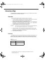
Crest factor
AC voltage and current accuracies are affected by the crest factor of the waveform, the
ratio of the peak value to the RMS value. Table 2-3 lists the fundamental frequencies at
which the corresponding crest factor must be taken into account for accuracy calculations.
Table 2-3
Crest factor limitations
Crest factor
Fundamental frequency
2
3
4-5
50kHz
3kHz
1kHz
Test Equipment Depot - 800.517.8431 - 99 Washington Street Melrose, MA 02176
TestEquipmentDepot.com
2000-900 (J - Aug 2010) BOOK.fm Page 19 Wednesday, October 12, 2011 12:29 PM
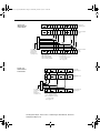
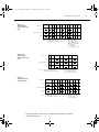
Figure 2-4
DC and AC voltage measurements
Model 2000
REM STEP SCAN CH1
TALK
LSTN
SRQ
SHIFT
FAST
TIMER HOLD TRIG
CH2
CH3
CH4
CH5
CH6
SLOW REL
FILT
AUTO
CH7
CH8 CH9
CH10 MATH
REAR
4W
MED
ERR
BUFFER STAT
2001 MULTIMETER
DC Voltage
Source
Input Resistance = 10MΩ on 1000V and 100V ranges ;
> 10GΩ on 10V, 1V and 100mV ranges.
Caution : Maximum Input = 1010V peak
Model 2000
REM STEP SCAN CH1
TALK
LSTN
SRQ
SHIFT
FAST
TIMER HOLD TRIG
CH2
CH3
CH4
CH5
CH6
SLOW REL
FILT
AUTO
CH7
CH
8
CH9
CH1
0
MATH
REAR
4W
MED
ERR
BUFFER STAT
2001 MULTIMETER
AC Voltage
Source
Input Impedence = 1MΩ and 100pF
Caution: Maximum Input = 750V RMS, 1000V peak, 8 x 10⁷ V•Hz
Low level considerations
For sensitive measurements, external considerations beyond the Model 2000 affect the
accuracy. Effects not noticeable when working with higher voltages are significant in microvolt signals. The Model 2000 reads only the signal received at its input; therefore, it is important that this signal be properly transmitted from the source. The following paragraphs
indicate factors that affect accuracy, including stray signal pick-up and thermal offsets.
Shielding
AC voltages that are extremely large compared with the DC signal to be measured may
produce an erroneous output. Therefore, to minimize AC interference, the circuit should be
shielded with the shield connected to the Model 2000 INPUT LO (particularly for low level
sources). Improper shielding can cause the Model 2000 to behave in one or more of the
following ways:
•
•
•
Unexpected offset voltages.
Inconsistent readings between ranges.
Sudden shifts in reading.
To minimize pick-up, keep the voltage source and the Model 2000 away from strong AC
magnetic sources. The voltage induced due to magnetic flux is proportional to the area of
the loop formed by the input leads. Therefore, minimize the loop area of the input leads and
connect each signal at only one point.
NOTE
Shielded cables should be used for input circuits to avoid interference caused by
conducting RF.
Test Equipment Depot - 800.517.8431 - 99 Washington Street Melrose, MA 02176
TestEquipmentDepot.com
2000-900 (J - Aug 2010) BOOK.fm Page 20 Wednesday, October 12, 2011 12:29 PM
Thermal EMFs
Thermal EMFs (thermoelectric potentials) are generated by thermal differences between
the junctions of dissimilar metals. These can be large compared to the signal that the Model
2000 can measure. Thermal EMFs can cause the following conditions:
•
•
Instability or zero offset is much higher than expected.
The reading is sensitive to (and responds to) temperature changes. This effect can
be demonstrated by touching the circuit, by placing a heat source near the circuit, or
by a regular pattern of instability (corresponding to changes in sunlight or the activation of heating and air conditioning systems).
To minimize the drift caused by thermal EMFs, use copper leads to connect the circuit to
the Model 2000. A banana plug generates a few microvolts. A clean copper conductor such
as #10 bus wire is ideal for this application. The leads to the input may be shielded or unshielded, as necessary. Refer to “Shielding”.
Widely varying temperatures within the circuit can also create thermal EMFs. Therefore,
maintain constant temperatures to minimize these thermal EMFs. A shielded enclosure
around the circuit under test also helps by minimizing air currents.
The REL control can be used to null out constant offset voltages.
NOTE
Additional thermals may be generated by the optional scanner cards.
Test Equipment Depot - 800.517.8431 - 99 Washington Street Melrose, MA 02176
TestEquipmentDepot.com
2000-900 (J - Aug 2010) BOOK.fm Page 21 Wednesday, October 12, 2011 12:29 PM
AC voltage offset
The Model 2000, at 5½ digits resolution, will typically display 100 counts of offset on AC
volts with the input shorted. This offset is caused by the offset of the TRMS converter. This
offset will not affect reading accuracy and should not be zeroed out using the REL feature.
The following equation expresses how this offset (VOFFSET) is added to the signal input (VIN):
Displayed reading =
2
( V IN ) + ( V OFFSET )
2
Example: Range = 1VAC
Offset = 100 counts (1.0mV)
Input = 100mV RMS
2
Displayed reading =
( 100mV ) + ( 1.0mV )
Displayed reading =
( 0.01V ) + ( 1 × 10
–6
2
V)
Displayed reading = 0.100005
The offset is seen as the last digit, which is not displayed. Therefore, the offset is negligible. If the REL feature were used to zero the display, the 100 counts of offset would be
subtracted from VIN, resulting in an error of 100 counts in the displayed reading.
See Section 3 — Measurement Options for information that explain the configuration options for DC and AC voltage measurements.
Test Equipment Depot - 800.517.8431 - 99 Washington Street Melrose, MA 02176
TestEquipmentDepot.com
2000-900 (J - Aug 2010) BOOK.fm Page 22 Wednesday, October 12, 2011 12:29 PM
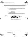
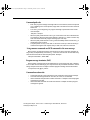
The Model 2000 can make DCI measurements from 10nA to 3A and ACI measurements
from 1µAm to 3A RMS.
NOTE
See the previous discussion about crest factor in “Measuring voltage” in this section.
Assuming factory default conditions, the basic procedure is as follows:
1.
2.
3.
4.
Connect test leads to the AMPS and INPUT LO terminals. The front inputs must be
used; place the INPUTS button in the FRONT position.
Select the measurement function by pressing DCI or ACI.
Pressing AUTO toggles autoranging. Notice the AUTO annunciator is displayed with
autoranging. If you want manual ranging, use the RANGE and keys to select
a measurement range consistent with the expected current.
Connect test leads to the source as shown in Figure 2-5.
CAUTION
5.
6.
Figure 2-5
DC and AC current measurements
Do not apply more than 3A, 250V to the input or the AMPS fuse will opencircuit.
Observe the display. If the “OVERFLOW” message is displayed, select a higher
range until a normal reading is displayed (or press AUTO for autoranging). Use the
lowest possible range for the best resolution.
Take readings from the display.
Model 2000
REM STEP SCAN CH1
TALK
LSTN
SRQ
SHIFT
FAST
TIMER HOLD TRIG
CH2
CH3
CH4
CH5
CH6
SLOW REL
FILT
AUTO
CH7
CH
8
CH9
CH1
0
MATH
REAR
4W
MED
ERR
BUFFER STAT
2001 MULTIMETER
Current
Source
Caution: Maximum Input = 3A DC or RMS
Test Equipment Depot - 800.517.8431 - 99 Washington Street Melrose, MA 02176
TestEquipmentDepot.com
2000-900 (J - Aug 2010) BOOK.fm Page 23 Wednesday, October 12, 2011 12:29 PM
AMPS fuse replacement
WARNING
1.
2.
Turn off the power and disconnect the power line and test leads.
From the front panel, gently push in the AMPS jack with your thumb and rotate the
fuse carrier one-quarter turn counter-clockwise. Release pressure on the jack and
its internal spring will push the jack out of the socket.
Remove the fuse and replace it with the same type (3A, 250V, fast blow, 5 × 20mm).
The Keithley part number is FU-99-1.
CAUTION
4.
Make sure the instrument is disconnected from the power line and other
equipment before replacing the AMPS fuse.
Do not use a fuse with a higher current rating than specified or instrument
damage may occur. If the instrument repeatedly blows fuses, locate and
correct the cause of the trouble before replacing the fuse. See the optional
Model 2000 Repair Manual for troubleshooting information.
Install the new fuse by reversing the procedure above.
See Section 3 — Measurement Options for information that explains the configuration options for DC and AC current measurements.
Test Equipment Depot - 800.517.8431 - 99 Washington Street Melrose, MA 02176
TestEquipmentDepot.com
2000-900 (J - Aug 2010) BOOK.fm Page 24 Wednesday, October 12, 2011 12:29 PM
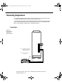
Measuring resistance
The Model 2000 can make 2-wire and 4-wire resistance measurements from 100µΩ to
120MΩ.
Connections
Assuming factory default conditions, the basic procedure is as follows:
1.
2.
4.
Connect test leads to the Model 2000 as follows:
A. For Ω2-wire, connect the test leads to INPUT HI and LO.
B. For Ω4-wire, connect the test leads to INPUT HI and LO, and SENSE Ω4 WIRE
HI and LO. Recommended Kelvin test probes include the Keithley Models 5805
and 5806. Either the front or rear inputs can be used; place the INPUTS button
in the appropriate position.
Select the measurement function by pressing Ω2 or Ω4.
Pressing AUTO toggles autoranging. Notice the AUTO annunciator is displayed with
autoranging. If you want manual ranging, use the RANGE and ▼ keys to select a
measurement range consistent with the expected resistance.
Connect test leads to the resistance as shown in Figure 2-6.
CAUTION
5.
6.
Do not apply more than 1000V peak between INPUT HI and LO or instrument damage may occur.
Observe the display. If the “OVERFLOW” message is displayed, select a higher
range until a normal reading is displayed. Use the lowest possible range for the best
resolution.
Take a reading from the display.
Test Equipment Depot - 800.517.8431 - 99 Washington Street Melrose, MA 02176
TestEquipmentDepot.com
2000-900 (J - Aug 2010) BOOK.fm Page 25 Wednesday, October 12, 2011 12:29 PM
Figure 2-6
Two- and fourwire resistance
measurements
Model 2000
REM STEP SCAN CH1
TALK
LSTN
SRQ
SHIFT
FAST
TIMER HOLD TRIG
CH2
CH3
CH4
CH5
CH6
SLOW REL
FILT
AUTO
CH7
CH
8
CH9
CH1
0
Shielded
Cable
Optional shield
MATH
REAR
4W
MED
ERR
BUFFER STAT
2001 MULTIMETER
Resistance
Under Test
Note: Source current flows from the INPUT
HI to INPUT LO terminals.
Model 2000
REM STEP SCAN CH1
TALK
LSTN
SRQ
SHIFT
FAST
TIMER HOLD TRIG
CH2
CH3
CH4
CH5
CH6
SLOW REL
FILT
AUTO
CH7
CH
8
CH9
CH1
0
Shielded
Cable
Optional shield
MATH
REAR
4W
MED
ERR
BUFFER STAT
2001 MULTIMETER
Resistance
Under Test
Note: Source current flows from the INPUT
HI to INPUT LO terminals.
To achieve a stable reading, it helps to shield resistances greater than 100kΩ. Place the
resistance in a shielded enclosure and connect the shield to the INPUT LO terminal of the
instrument electrically.
See Section 3—Measurement Options for information that explains the configuration options for 2-wire and 4-wire resistance measurements.
Test Equipment Depot - 800.517.8431 - 99 Washington Street Melrose, MA 02176
TestEquipmentDepot.com
2000-900 (J - Aug 2010) BOOK.fm Page 26 Wednesday, October 12, 2011 12:29 PM
Measuring frequency and period
The Model 2000 can make frequency measurements from 3Hz to 500kHz on voltage
ranges of 100mV, 1V, 10V, 100V, and 750V. Period measurements can be taken from 2µs
to 333ms on the same voltage ranges as the frequency.
The instrument uses the volts input terminals to measure frequency. The AC voltage
range can be changed with the RANGE and keys. The signal voltage must be greater
than 10% of the full-scale range.
CAUTION
The voltage limit is subject to the 8 × 10⁷V•Hz product.
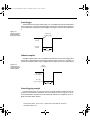
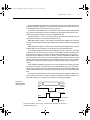
Trigger level
Frequency and Period use a zero-crossing trigger, meaning that a count is taken when
the frequency crosses the zero level. The Model 2000 uses a reciprocal counting technique
to measure frequency and period. This method generates constant measurement resolution
for any input frequency. The multimeter’s AC voltage measurement section performs input
signal conditioning.
Test Equipment Depot - 800.517.8431 - 99 Washington Street Melrose, MA 02176
TestEquipmentDepot.com
2000-900 (J - Aug 2010) BOOK.fm Page 27 Wednesday, October 12, 2011 12:29 PM
Connections
Assuming factory default conditions, the basic procedure is as follows:
1.
2.
3.
Connect test leads to the INPUT HI and LO terminals of the Model 2000. Either the
front or rear inputs can be used; place the INPUTS button in the appropriate position.
Select the FREQ or PERIOD function.
Connect test leads to the source as shown in Figure 2-7.
CAUTION
4.
Do not exceed 1000V peak between INPUT HI and INPUT LO or instrument
damage may occur.
Take a reading from the display.
See Section 3—Measurement Options for information that explains the configuration options for frequency and period measurements.
Figure 2-7
Frequency and
period measurements
Model 2000
REM STEP SCAN CH1
TALK
LSTN
SRQ
SHIFT
FAST
TIMER HOLD TRIG
CH2
CH3
CH4
CH5
CH6
SLOW REL
FILT
AUTO
CH7
CH
8
CH9
CH1
0
MATH
REAR
4W
MED
ERR
BUFFER STAT
2001 MULTIMETER
AC Voltage
Source
Input Impedance = 1MΩ in parallel with <100pF
Caution: Maximum Input = 1000V peak, 8 x 10⁷ V•Hz
Test Equipment Depot - 800.517.8431 - 99 Washington Street Melrose, MA 02176
TestEquipmentDepot.com
2000-900 (J - Aug 2010) BOOK.fm Page 28 Wednesday, October 12, 2011 12:29 PM
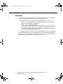
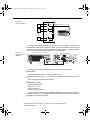
Measuring temperature
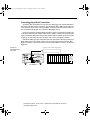
The Model 2000 measures temperature with thermocouples. The temperature measurement ranges available depend on the type of thermocouple chosen.
Thermocouples can be connected to the Model 2001-TCSCAN card, which plugs into the
option slot of the Model 2000, or to an external thermocouple card, such as a Model 7057A,
7402, or 7014 installed in a Model 7001 or 7002 Switch System.
Connections
Figure 2-8
Thermocouple
temperature
measurements
2001-TCSCAN
+
-
CH 2
Note: This thermocouple card
must be inserted into a
Keithley Model 2000.
Note: Front or rear inputs
can be used.
Input
HI
Model 2000
REM STEP SCAN CH1
TALK
LSTN
SRQ
SHIFT
FAST
TIMER HOLD TRIG
CH2
CH3
CH4
CH5
CH6
SLOW REL
FILT
AUTO
CH7
CH
8
CH9
CH1
0
MATH
REAR
4W
MED
ERR
BUFFER STAT
2001 MULTIMETER
Input
LO
OUT A HI
OUT A LO
Test Equipment Depot - 800.517.8431 - 99 Washington Street Melrose, MA 02176
TestEquipmentDepot.com
2000-900 (J - Aug 2010) BOOK.fm Page 29 Wednesday, October 12, 2011 12:29 PM
Configuration
The following information explains the various configuration options for temperature mea
surements. To select and configure the thermocouple measurement:
Press SHIFT then TCOUPL. Three choices are available using the
•
•
•
and
keys:
UNITS — C, K, F (Centigrade, Kelvin, Fahrenheit). This parameter selects the displayed units for temperature measurements.
TYPE — J, K, T (thermocouple type).
JUNC — SIM, CH1 (simulated or referenced at Channel 1). Typically, a thermocouple card uses a single reference junction. The Model 2000 can simulate a reference
junction temperature or use the reference junction on a switching card. Typical reference junction temperatures are 0°C and 23°C.
A simulated reference temperature is the temperature of the junction where the thermocouple voltage is sensed. It is room temperature if the thermocouple wire is terminated to
banana jacks and corrected directly to the multimeter. The accuracy of a temperature measurement depends on the accuracy of the reference junction.
Test Equipment Depot - 800.517.8431 - 99 Washington Street Melrose, MA 02176
TestEquipmentDepot.com
2000-900 (J - Aug 2010) BOOK.fm Page 30 Wednesday, October 12, 2011 12:29 PM
Math
Model 2000 math operations are divided into four categories:
•
•
•
•
mX+b and percent
dBm and dB calculations
Statistics of buffered readings
Limit testing
The first two categories are discussed here; buffered reading statistics and reading limit
testing are described in Section 3 — Measurement Options.
The procedure to select and configure a math operation is summarized as follows:
1.
2.
Press SHIFT then the appropriate math key.
Configure the parameters for the math operation. Press ENTER when done. (Press
SHIFT then the related math function to end the calculation.)
NOTES Once enabled for a function, the mX+b and percentage calculations are in effect
across function changes.
The Model 2000 uses IEEE-754 floating point format for math calculations.
MX + B
This math operation lets you manipulate normal display readings (X) mathematically according to the following calculation:
Y= mX + b
where: X is the normal display reading
m and b are user-entered constants for scale factor and offset
Y is the displayed result
Test Equipment Depot - 800.517.8431 - 99 Washington Street Melrose, MA 02176
TestEquipmentDepot.com
2000-900 (J - Aug 2010) BOOK.fm Page 31 Wednesday, October 12, 2011 12:29 PM
Configuration
To configure the mX+b calculation, perform the following steps:
1.
Press SHIFT then MX+B to display the present scale factor:
M: +1.000000 ^
3.
Enter a value and units prefix. Use the
and
keys to choose a numerical place
and use the
and keys to increment or decrement the digits.
Press ENTER to confirm the M value and display the B value:
B: +00.00000 m
4.
5.
Enter a value and units prefix.
Press ENTER to confirm the B value and display the UNITS designation:
MXB
6.
Scroll through the letters to change and press ENTER when done.
The Model 2000 then displays the result of the calculation.
Percent
This item selects the percentage calculation and lets you specify a reference value. The
displayed reading will be expressed as a percent deviation from the reference value. The
percentage calculation is performed as follows:
Input - Reference
Percent = ------------------------------------------ × 100%
Reference
where: Input is the normal display reading.
Reference is the user entered constant.
Percent is the displayed result.
Configuration
To configure the percent calculation, perform the following steps:
1.
Press SHIFT then % to display the present value:
REF:+1.000000^
3.
Enter a reference sign, value, and units prefix. Use the
and
keys to choose
a numerical place and use the and keys to increment or decrement the digits.
Press ENTER when done.
The Model 2000 will display the result of the calculation. The result is positive when the
input exceeds the reference and negative when the input is less than the reference. Engineering units are used to show values in the range 1 nano to 1000G. Exponential notation is
used above that range.
Test Equipment Depot - 800.517.8431 - 99 Washington Street Melrose, MA 02176
TestEquipmentDepot.com
2000-900 (J - Aug 2010) BOOK.fm Page 32 Wednesday, October 12, 2011 12:29 PM
dBm is defined as decibels above or below a 1mW reference. With a user-programmable
reference impedance, the Model 2000 reads 0dBm when the voltage needed to dissipate
1mW through the reference impedance is applied. The relationship between dBm, a reference impedance, and the voltage is defined by the following equation:
⎛ V2 /Z
⎞
⎝ IN REF⎠
dBm = 10 log --------------------------------1mW
Where: VIN is the DC or AC input signal.
ZREF is the specified reference impedance.
NOTE
Do not confuse reference impedance with input impedance. The input impedance
of the instrument is not modified by the dBm parameter.
If a relative value is in effect when dBm is selected, the value is converted to dBm then
REL is applied to dBm. If REL is applied after dBm has been selected, dBm math has REL
applied to it.
To set the reference impedance, perform the following steps:
1.
After selecting dBm, the present reference impedance is displayed (1-9999Ω):
REF: 0000
2.
To change the reference impedance, use the
and
keys to select the numeric
position. Then use the and keys to select the desired value. Be sure to press
ENTER after changing the reference impedance.
NOTES dBm is valid for positive and negative values of DC volts.
The mX+b and percent math operations are applied after the dBm or dB math. For
example, if mX+b is selected with m=10 and b=0, the display will read 10.000 MXB
for a 1VDC signal. If dBm is selected with ZREF = 50Ω, the display will read
130MXB.
Test Equipment Depot - 800.517.8431 - 99 Washington Street Melrose, MA 02176
TestEquipmentDepot.com
2000-900 (J - Aug 2010) BOOK.fm Page 33 Wednesday, October 12, 2011 12:29 PM
Expressing DC or AC voltage in dB makes it possible to compress a large range of measurements into a much smaller scope. The relationship between dB and voltage is defined
by the following equation:
V IN
dB= 20 log ----------------V REF
where: VIN is the DC or AC input signal.
VREF is the specified voltage reference level.
The instrument will read 0dB when the reference voltage level is applied to the input.
If a relative value is in effect when dB is selected, the value is converted to dB then REL
is applied to dB. If REL is applied after dB has been selected, dB has REL applied to it.
To set the reference voltage, perform the following steps:
1.
After selecting dB, the present reference voltage level is displayed:
REF: +0.000000
2.
To change the reference level, use the
and
keys to select the numeric
position. Then use the
and keys to select the desired value. Be sure to press
ENTER after changing the reference voltage.
NOTES The dB calculation takes the absolute value of the ratio VIN / VREF
The largest negative value of dB is -160dB. This will accommodate a ratio of VIN
= 1µV and VREF = 1000V.
Test Equipment Depot - 800.517.8431 - 99 Washington Street Melrose, MA 02176
TestEquipmentDepot.com
2000-900 (J - Aug 2010) BOOK.fm Page 34 Wednesday, October 12, 2011 12:29 PM
The Model 2000 uses the 1kΩ range to measure circuit continuity. After selecting continuity, the unit prompts you for a threshold resistance level (1Ω-1000Ω). The Model 2000
alerts you with a beep when a reading is below the set level.
To measure the continuity of a circuit, press SHIFT then CONT, set the threshold resistance level and connect the circuit.
NOTE
Continuity has a non-selectable reading rate of FAST (0.1 PLC).
Connect the circuit you want to test to the INPUT HI and INPUT LO terminals of the Model
2000. The test current flows from the INPUT HI as shown in Figure 2-9.
Model 2000
Figure 2-9
Continuity measurements
REM STEP SCAN CH1
TALK
LSTN
SRQ
SHIFT
FAST
TIMER HOLD TRIG
CH2
CH3
CH4
CH5
CH6
SLOW REL
FILT
AUTO
CH7
CH
8
CH9
CH1
0
MATH
REAR
4W
MED
ERR
BUFFER STAT
2001 MULTIMETER
Resistance
Under Test
Note: Source current flows from the INPUT
HI to INPUT LO terminals.
You can define a threshold resistance from 1Ω to 1000Ω. The factory setting is 10Ω. Follow these steps to define the resistance level:
1.
3.
Press SHIFT then CONT.
Use the
and
keys to choose a numerical place and use the ▲ and ▼ keys to
increment or decrement the digits. Enter a value from 1 to 1000.
Press ENTER to confirm your setting.
Test Equipment Depot - 800.517.8431 - 99 Washington Street Melrose, MA 02176
TestEquipmentDepot.com
2000-900 (J - Aug 2010) BOOK.fm Page 35 Wednesday, October 12, 2011 12:29 PM
Testing diodes
With a Model 2000, you can measure the forward voltage drop of general-purpose diodes
and the zener voltage of zener diodes. To test diodes, press SHIFT then
, set the test
current range, connect the diode, and take a reading from the display.
NOTE
Diode test has a non-selectable reading rate of MEDium (1 PLC).
Connections
Connect the diode leads to the INPUT HI and INPUT LO terminals on the Model 2000.
The test current flows from the INPUT HI terminal as shown in Figure 2-10.
Model 2000
Figure 2-10
Diode testing
REM STEP SCAN CH1
TALK
LSTN
SRQ
SHIFT
FAST
TIMER HOLD TRIG
CH2
CH3
CH4
CH5
CH6
SLOW REL
FILT
AUTO
CH7
CH
8
CH9
CH1
0
MATH
REAR
4W
MED
ERR
BUFFER STAT
2001 MULTIMETER
General-purpose
diode
Model 2000
REM STEP SCAN CH1
TALK
LSTN
SRQ
SHIFT
FAST
TIMER HOLD TRIG
CH2
CH3
CH4
CH5
CH6
SLOW REL
FILT
AUTO
CH7
CH
8
CH9
CH1
0
MATH
REAR
4W
MED
ERR
BUFFER STAT
2001 MULTIMETER
Zener
diode
Note: Source current flows from the
INPUT HI to INPUT LO terminals.
Range
You can set the test current range from the front panel. The choices are 1mA, 100µA, and
10µA. The factory test current setting is 1mA. To set the test current, do following:
1.
Press SHIFT then
.
Use the ▲ and ▼ keys to scroll through the three test current selections.
The diode test measures voltages on the 3V range for the 1mA test current and the 10V
range for the 100µA and 10µA ranges. If a reading is more than 10V, the Model 2000 displays the “OVERFLOW” status message.
Test Equipment Depot - 800.517.8431 - 99 Washington Street Melrose, MA 02176
TestEquipmentDepot.com
2000-900 (J - Aug 2010) BOOK.fm Page 36 Wednesday, October 12, 2011 12:29 PM
Test Equipment Depot - 800.517.8431 - 99 Washington Street Melrose, MA 02176
TestEquipmentDepot.com
2000-900 (J - Aug 2010) BOOK.fm Page 1 Wednesday, October 12, 2011 12:29 PM
3
Measurement
Options
Test Equipment Depot - 800.517.8431 - 99 Washington Street Melrose, MA 02176
TestEquipmentDepot.com
2000-900 (J - Aug 2010) BOOK.fm Page 2 Wednesday, October 12, 2011 12:29 PM
Measurement Options
This section describes the front panel features of the Model 2000. For those measurement options accessible only by a remote interface, refer to Sections 4 and 5. This section
is organized as follows:
•
•
•
•
•
•
Measurement configuration — Describes ranging, filtering, relative readings, digits of
resolution, and measurement rate.
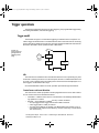
Trigger operations — Uses a trigger model to explain trigger modes and sources.
Buffer operations — Discusses the reading storage buffer and buffer statistics.
Limit operations — Defines how to set reading limits.
Scan operations — Explains the internal and external scanning capabilities.
System operations — Gives details on setup saving and restoring, selecting a remote
interface, and accessing test and calibration.
Test Equipment Depot - 800.517.8431 - 99 Washington Street Melrose, MA 02176
TestEquipmentDepot.com
2000-900 (J - Aug 2010) BOOK.fm Page 3 Wednesday, October 12, 2011 12:29 PM
Measurement Options
3-3
The following paragraphs discuss configuring the multimeter for making measurements.
See the end of Appendix A for information about optimizing readings for speed or accuracy.
The selected measurement range affects both the ultimate digits and accuracy of the
measurements as well as the maximum signal that can be measured. The range setting
(fixed or auto) for each measurement function is saved when changing functions.
The full scale readings for every range on each function are 20% overrange except for
the 1000VDC, 750VAC, 3ADC, 3AAC, and diode test ranges.
Input values more than the maximum readings cause the "OVERFLOW" messages to be
displayed.
To select a range, simply press the RANGE or key. The instrument changes one
range per keypress. The selected range is displayed for one second.
If the instrument displays the "OVERFLOW" message on a particular range, select a higher range until an on-range reading is displayed. Use the lowest range possible without causing an overflow to ensure best accuracy and resolution.
Note that the temperature and continuity functions have just one range.
To enable autoranging, press the AUTO key. The AUTO annunciator turns on when autoranging is selected. While autoranging is selected, the instrument automatically chooses
the best range to measure the applied signal. Autoranging should not be used when optimum speed is required.
Note that up-ranging occurs at 120% of range, while down-ranging occurs at 10% of nominal range.
To cancel autoranging, press AUTO or the RANGE or
autoranging leaves the instrument on the present range.
key. Pressing AUTO to cancel
The AUTO key has no effect on the temperature, continuity, and diode test functions.
Test Equipment Depot - 800.517.8431 - 99 Washington Street Melrose, MA 02176
TestEquipmentDepot.com
2000-900 (J - Aug 2010) BOOK.fm Page 4 Wednesday, October 12, 2011 12:29 PM
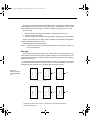
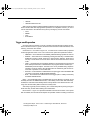
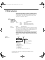
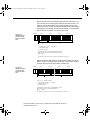
FILTER lets you set the filter response to stabilize noisy measurements. The Model 2000
uses a digital filter, which is based on reading conversions. The displayed, stored, or transmitted reading is simply an average of a number of reading conversions (from 1 to 100).
To select a filter:
1.
2.
3.
Press FILTER once if the FILT annunciator is off; press twice if FILT is on.
Enter the number of readings.
Select the type of filter you want (moving average or repeating), then press ENTER.
The FILT annunciator turns on. When a filter is enabled, the selected filter configuration
for that measurement function is in effect.
Pressing FILTER once disables the filter.
NOTE
The filter can be set for any measurement function except frequency, period, continuity, and diode test.
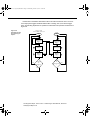
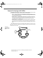
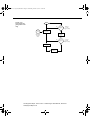
Filter types
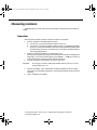
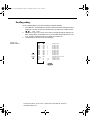
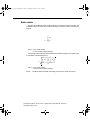
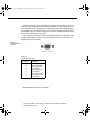
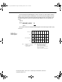
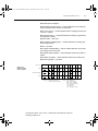
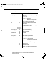
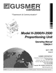
The moving average filter uses a first-in, first-out stack. When the stack becomes full, the
measurement conversions are averaged, yielding a reading. For each subsequent conversion placed into the stack, the oldest conversion is discarded, and the stack is re-averaged,
yielding a new reading.
For the repeating filter, the stack is filled and the conversions are averaged to yield a reading. The stack is then cleared and the process starts over. Choose this filter for scanning so
readings from other channels are not averaged with the present channel.
Figure 3-1
Moving average
and repeating filters
Conversion #10
#9
#8
#7
#6
#5
#4
#3
#2
Conversion #1
Reading
#1
Conversion #11
#10
#9
#8
#7
#6
#5
#4
#3
Conversion #2
Reading
#2
Conversion #12
#11
#10
#9
#8
#7
#6
#5
#4
Conversion #3
Reading
#3
Reading
#2
Conversion #30
#29
#28
#27
#26
#25
#24
#23
#22
Conversion #21
Reading
#3
A. Type - Moving Average, Readings = 10
Conversion #10
#9
#8
#7
#6
#5
#4
#3
#2
Conversion #1
Reading
#1
Conversion #20
#19
#18
#17
#16
#15
#14
#13
#12
Conversion #11
B. Type - Repeating, Readings = 10
Test Equipment Depot - 800.517.8431 - 99 Washington Street Melrose, MA 02176
TestEquipmentDepot.com
2000-900 (J - Aug 2010) BOOK.fm Page 5 Wednesday, October 12, 2011 12:29 PM
Response time
The filter parameters have speed and accuracy tradeoffs for the time needed to display,
store, or output a filtered reading. These affect the number of reading conversions for speed
versus accuracy and response to input signal changes.
Relative
The rel (relative) function can be used to null offsets or subtract a baseline reading from
present and future readings. When rel is enabled, the instrument uses the present reading
as a relative value. Subsequent readings will be the difference between the actual input value and the rel value.
You can define a rel value for each function. Once a rel value is established for a measurement function, the value is the same for all ranges. For example, if 50V is set as a rel
value on the 100V range, the rel is also 50V on the 1000V, 10V, 1V, and 100mV ranges.
Thus, when you perform a zero correction for DCV, Ω2, and Ω4 measurements by enabling REL, the displayed offset becomes the reference value. Subtracting the offset from
the actual input zeroes the display, as follows:
Actual Input – Reference = Displayed Reading
A rel value can be as large as the highest range.
Selecting a range that cannot accommodate the rel value does not cause an overflow
condition, but it also does not increase the maximum allowable input for that range. For example, on the 10V range, the Model 2000 still overflows for a 12V input.
To set a rel (relative) value, press REL key when the display shows the value you want
as the relative value. The REL annunciator turns on. Pressing REL a second time disables
rel.
You can input a REL value manually using the mX+b function. Set M for 1 and B for any
value you want. Pressing REL enables that value to be the relative value. See Section 2 for
more information on the mX+b function.
Digits
The display resolution of a Model 2000 reading depends on the DIGITS setting. It has no
effect on the remote reading format. The number of displayed digits does not affect accuracy
or speed. Those parameters are controlled by the RATE setting.
Perform the following steps to set digits for a measurement function:
1.
NOTE
Press the desired function.
Press the DIGITS key until the desired number of digits is displayed (3½ to 6½).
Frequency and period can be displayed with four to seven digits.
Test Equipment Depot - 800.517.8431 - 99 Washington Street Melrose, MA 02176
TestEquipmentDepot.com
2000-900 (J - Aug 2010) BOOK.fm Page 6 Wednesday, October 12, 2011 12:29 PM
Rate
The RATE operation sets the integration time of the A/D converter, the period of time the
input signal is measured (also known as aperture). The integration time affects the usable
digits, the amount of reading noise, as well as the ultimate reading rate of the instrument.
The integration time is specified in parameters based on a number of power line cycles
(NPLC), where 1 PLC for 60Hz is 16.67msec and 1 PLC for 50Hz and 400Hz is 20msec.
In general, the fastest integration time (FAST (0.1 PLC) from the front panel, 0.01 PLC
from the bus) results in increased reading noise and fewer usable digits, while the slowest
integration time (10 PLC) provides the best common-mode and normal-mode rejection. Inbetween settings are a compromise between speed and noise.
The RATE parameters are explained as follows:
•
•
•
NOTE
FAST sets integration time to 0.1 PLC. Use FAST if speed is of primary importance
(at the expense of increased reading noise and fewer usable digits).
MEDium sets integration time to 1 PLC. Use MEDium when a compromise between
noise performance and speed is acceptable.
SLOW sets integration time to 10 PLC. SLOW provides better noise performance at
the expense of speed.
The integration time can be set for any measurement function except frequency,
period, continuity (FAST), and diode test (MEDium). For frequency and period,
this value is gate time or aperture.
For the AC functions, MEDium and SLOW have no effect on the number of power
line cycles. See the discussion on “Bandwidth” that follows.
Test Equipment Depot - 800.517.8431 - 99 Washington Street Melrose, MA 02176
TestEquipmentDepot.com
2000-900 (J - Aug 2010) BOOK.fm Page 7 Wednesday, October 12, 2011 12:29 PM
Bandwidth
The rate setting for AC voltage and current measurements determines the bandwidth setting:
•
•
•
Slow — 3Hz to 300kHz.
Medium — 30Hz to 300kHz.
Fast — 300Hz to 300kHz.
Bandwidth is used to specify the lowest frequency of interest. When the Slow bandwidth
(3Hz to 300kHz) is chosen, the signal goes through an analog RMS converter. The output
of the RMS converter goes to a fast (1kHz) sampling A/D and the RMS value is calculated
from 1200 digitized samples (1.2s).
When the Medium bandwidth (30Hz to 300kHz) is chosen, the same circuit is used. However, only 120 samples (120ms) are needed for an accurate calculation because the analog
RMS converter has turned most of the signal to DC.
In the Fast bandwidth (300Hz to 300kHz), the output of the analog RMS converter (nearly
pure DC at these frequencies) is simply measured at 1 PLC (16.6ms).
Table 3-1 lists the rate settings for the various measurement functions. The FAST, MED,
and SLOW annunciators are only lit when conditions in the table are met. In other case, the
annunciators are turned off.
Table 3-1
Rate settings for the measurement functions
Function
DCV, DCI
ACV, ACI
Ω2W, Ω4W
FREQ, PERIOD
dB, dBm (ACV)
dB, dBm (DCV)
Continuity
Diode test
Rate
Fast
Medium
Slow
NPLC=0.1
NPLC=1, BW=300
NPLC=0.1
APER=1s
NPLC=1, BW=300
NPLC=0.1
NPLC=0.1
N/A
NPLC=1
NPLC=X, BW=30
NPLC=1
APER=1s
NPLC=X, BW=30
NPLC=1
N/A
NPLC=1
NPLC=10
NPLC=X, BW=3
NPLC=10
APER=1s
NPLC=X, BW=3
NPLC=10
N/A
N/A
Notes:
NPLC = number of power line cycles.
BW = lower limit of bandwidth (in Hz).
APER = aperture in seconds.
N/A = not available.
X = setting ignored.
Test Equipment Depot - 800.517.8431 - 99 Washington Street Melrose, MA 02176
TestEquipmentDepot.com
2000-900 (J - Aug 2010) BOOK.fm Page 8 Wednesday, October 12, 2011 12:29 PM
Trigger operations
The following paragraphs discuss front panel triggering, the programmable trigger delay,
the reading hold feature, and external triggering.
Trigger model
The flowchart of Figure 3-2 summarizes triggering as viewed from the front panel. It is
called a trigger model because it is modeled after the SCPI commands used to control triggering. Note that for stepping and scanning, the trigger model has additional control blocks.
These are described in “Scan operations” later in this section.
Figure 3-2
Front panel triggering without
stepping/scanning
Idle
Control
Source
Event
Detection
Immediate
External
Output
Trigger
Delay
Device
Action
Idle
The instrument is considered to be in the idle state whenever it is not performing any measurements or scanning functions. From the front panel, the unit is considered idle at the end
of a step or scan operation when the reading for the last channel remains displayed. To restore triggers, use the SHIFT-HALT keys.
Once the Model 2000 is taken out of idle, operation proceeds through the flowchart.
Control source and event detection
The control source holds up operation until the programmed event occurs and is detected. The control sources are described as follows:
•
•
Immediate — With this control source, event detection is immediately satisfied allowing operation to continue.
External — Event detection is satisfied for any of three conditions:
• An input trigger via the Trigger Link line EXT TRIG is received.
• A bus trigger (GET or *TRG) is received.
• The front panel TRIG key is pressed. (The Model 2000 must be taken out of remote before it will respond to the TRIG key. Use the LOCAL key or send LOCAL
716 over the bus.)
Test Equipment Depot - 800.517.8431 - 99 Washington Street Melrose, MA 02176
TestEquipmentDepot.com
2000-900 (J - Aug 2010) BOOK.fm Page 9 Wednesday, October 12, 2011 12:29 PM
Delay
A programmable delay is available after event detection. It can be set manually or an auto
delay can be used. With auto delay, the Model 2000 selects a delay based on the function
and range. The AUTO settings are listed in Table 3-2.
Table 3-2
Auto delay settings
Function
DCV
ACV
FREQ
DCI
ACI
Ω2W, Ω4W
Continuity
Diode testing
Range and delay
100mV
1ms
100mV
400ms
100mV
1ms
1V
1ms
1V
400ms
1V
1ms
10V
1ms
10V
400ms
10V
1ms
100V
5ms
100V
400ms
100V
1ms
10mA
2ms
100mA
2ms
1A
2ms
1A
400ms
3A
2ms
3A
400ms
100Ω
3ms
1kΩ
3ms
1kΩ
3ms
1mA
1ms
10kΩ
13ms
100kΩ
25ms
100µA
1ms
10µA
1ms
1000V
5ms
750V
400ms
750V
1ms
1MΩ
100ms
10MΩ
150ms
100MΩ
250ms
The delay function is accessed by pressing the SHIFT-DELAY keys. The present delay
setting (AUTO or MANual) is displayed. Use the and keys to select the type of delay.
If MANual is chosen, also enter the duration of the delay. The maximum is shown following:
99H:99M:99.999S
Press ENTER to accept the delay or EXIT for no change.
Changing the delay to MANual on one function changes the delays on all functions to
MANual.
Test Equipment Depot - 800.517.8431 - 99 Washington Street Melrose, MA 02176
TestEquipmentDepot.com
2000-900 (J - Aug 2010) BOOK.fm Page 10 Wednesday, October 12, 2011 12:29 PM
Device actions
The primary device action is a measurement. However, the device action block could include the following additional actions:
•
•
•
Filtering — If the repeating filter is enabled, the instrument samples the specified
number of reading conversions to yeildl single filtered reading. Only one reading conversion is performed if the filter is disabled, or after the specified number of reading
conversions for a moving average filter is reached. The output of filter feeds hold.
Hold — With hold enabled, the first processed reading becomes the “seed” reading
and operation loops back within the device action block. After the next reading is processed, it is checked to see if it is within the selected window (0.01%, 0.1%, 1%,
10%) of the “seed” reading. If the reading is within the window, operation again loops
back within the device action block. This looping continues until the specified number
(2 to 100) consecutive readings are within the window. If one of the readings is not
within the window, the instrument acquires a new “seed” reading and the hold process continues.
Channel closure — When stepping or scanning, the last device action is to open the
previous channel (if closed) and close the next channel. Using the hold feature provides an auto settling time for the scanner relays. Each open/close transition will restart the hold process and a reading for each channel will not occur until the relay
settles.
Output trigger
After the device action, an output trigger occurs and is available at the rear panel Trigger
Link connector. This trigger can be used to trigger another instrument to perform an operation (e.g., select the next channel for an external scan).
Counters
The trigger model for stepping and scanning contains additional blocks for counting samples (the number of channels to scan) and counting triggers. These counters are explained
in the paragraph “Scan operations” later in this section.
Reading hold (autosettle)
When a hold reading is acquired as described in “Device actions”, an audible beep is
sounded (if enabled) and the reading is considered a “true measurement”. The reading is
held on the display until an “out of window” reading occurs to restart the hold process.
When operating remotely or scanning, the hold process seeks a new “seed"“once it has
been satisfied and the reading has been released. When operating from the front panel, the
hold process does not seek a new "seed" until the held condition is removed.
Test Equipment Depot - 800.517.8431 - 99 Washington Street Melrose, MA 02176
TestEquipmentDepot.com
2000-900 (J - Aug 2010) BOOK.fm Page 11 Wednesday, October 12, 2011 12:29 PM
Hold example
1.
2.
3.
Enable HOLD, select a window percentage and enter a count.
Apply test probes to a signal. Once the signal becomes stable enough to satisfy the
hold condition, the reading is released, and the beeper sounds (if enabled).
Remove the hold condition by lifting the probes. Hold will then seek a new “seed”.
External triggering
The EXT TRIG key selects triggering from two external sources: trigger link and the TRIG
key. When EXT TRIG is pressed, the TRIG annunciator lights and dashes are displayed to
indicate that instrument is waiting for an external trigger. From the front panel, you can press
the TRIG key to trigger a single reading. Pressing the EXT TRIG key again toggles you back
to continuous triggers.
The Model 2000 uses two lines of the Trigger Link rear panel connector as External Trigger (EXT TRIG) input and Voltmeter Complete (VMC) output. The EXT TRIG line allows the
Model 2000 to be triggered by other instruments. The VMC line allows the Model 2000 to
trigger other instruments.
At the factory, line 1 is configured as VMC and line 2 as EXT TRIG. (Changing this configuration is described in the optional Model 2000 Repair Manual.) A connector pinout is
shown in Figure 3-3.
Pin Number
Rear Panel Pinout
Figure 3-3
Rear panel pinout
8
4
2
Pin 2
External
Trigger
Input
6
7
5
3
1
Pin 1
Voltmeter
Complete
Output
Description
1
Voltmeter Complete Output
2
External Trigger Input
3
no connection *
4
no connection *
5
no connection *
6
no connection *
7
Signal Ground
8
Signal Ground
* Either pin 3 or 5 may be configured as an output instead
of pin 1. Either pin 4 or 6 may be configured as an input
instead of pin 2. See the optional Model 2000 Repair
Manual for details.
Test Equipment Depot - 800.517.8431 - 99 Washington Street Melrose, MA 02176
TestEquipmentDepot.com
2000-900 (J - Aug 2010) BOOK.fm Page 12 Wednesday, October 12, 2011 12:29 PM
External trigger
The EXT TRIG input requires a falling-edge, TTL-compatible pulse with the specifications
shown in Figure 3-4. In general, external triggers can be used to control measure operations.
For the Model 2000 to respond to external triggers, the trigger model must be configured for
it.
Figure 3-4
Trigger link input
pulse specifications (EXT TRIG)
Triggers on
Leading Edge
TTL High
(2V-5V)
TTL Low
(≤0.8V)
2µs
Minimum
Voltmeter complete
The VMC output provides a TTL-compatible output pulse that can be used to trigger other
instruments. The specifications for this trigger pulse are shown in Figure 3-5. Typically, you
would want the Model 2000 to output a trigger after the settling time of each measurement.
Figure 3-5
Trigger link output pulse specifications (VMC)
Meter
Complete
TTL High
(3.4V Typical)
TTL Low
(0.25V Typical)
10µs
Minimum
External triggering example
In a typical test system, you may want to close a channel and then measure the DUT connected to the channel with a multimeter. Such a test system is shown in Figure 3-6, which
uses a Model 2000 to measure ten DUTs switched by a Model 7011 multiplexer card in a
Model 7001/7002 Switch System.
Test Equipment Depot - 800.517.8431 - 99 Washington Street Melrose, MA 02176
TestEquipmentDepot.com
2000-900 (J - Aug 2010) BOOK.fm Page 13 Wednesday, October 12, 2011 12:29 PM
Figure 3-6
DUT test system
DUT
#1
1
DUT
#2
2
OUTPUT
2000 MULTIMETER
2000 Multimeter
DUT
#10
10
Card 1
7011 MUX Card
The Trigger Link connections for this test system are shown in Figure 3-7. Trigger Link of
the Model 2000 is connected to Trigger Link (either IN or OUT) of the Model 7001/7002. Note
that with the default trigger settings on the Model 7001/7002, line #1 is an input and line #2
is an output. This complements the trigger lines on the Model 2000.
Figure 3-7
Trigger link connections
7001 or 7002 Switch System
2000 Multimeter
WARNING:NO
NO INTERNAL
INTERNAL OPERATOR
OPERATOR SERVICABLE
SERVICABLE PARTS,SERVICE
PARTS,SERVICE BY
BY QUALIFIED
QUALIFIED PERSONNEL
PERSONNEL ONLY.
ONLY.
WARNING:NO
NO INTERNAL
INTERNAL OPERATOR
OPERATOR SERVICABLE
SERVICABLE PARTS,SERVICE
PARTS,SERVICE BY
BY QUALIFIED
QUALIFIED PERSONNEL
PERSONNEL ONLY.
ONLY.
HI
MADE IN
U.S.A.
IEEE-488
350V
PEAK
!
1000V
PEAK
(CHANGE IEEE ADDRESS
FROM FRONT PANEL)
TRIGGER
LINK
RS232
!
MADE IN USA
LO
SENSE
Ω 4W
CAUTION:FOR
FOR CONTINUED
CONTINUED PROTECTION
PROTECTION AGAINST
AGAINST FIRE
FIRE HAZARD,REPLACE
HAZARD,REPLACE FUSE
FUSE WITH
WITH SAME
SAME TYPE
TYPE AND
AND RATING.
RATING.
Trigger
Link
500V
INPUT PEAK
1
2
3
4
5
6
VMC
EXT TRIG
!
!
FUSE
LINE
250mAT
(SB)
100 VAC
120 VAC
125mAT
(SB)
220 VAC
240 VAC
LINE RATING
120
IN
OUT
50, 60
400HZ
17 VA MAX
CAUTION:FOR
FOR CONTINUED
CONTINUED PROTECTION
PROTECTION AGAINST
AGAINST FIRE
FIRE HAZARD,REPLACE
HAZARD,REPLACE FUSE
FUSE WITH
WITH SAME
SAME TYPE
TYPE AND
AND RATING.
RATING.
Trigger
Link Cable
(8501)
Trigger
Link
For this example, the Model 2000 and 7001/7002 are configured as follows:
Model 2000:
Factory defaults restored (accessed from SHIFT-SETUP)
External scanning, channels 1 - 10, no timer, 10 readings (accessed from SHIFT-CONFIG)
External triggers (accessed from EXT TRIG)
Model 7001 or 7002:
Factory defaults restored
Scan list = 1!1-1!10,
Number of scans = 1
Channel spacing = TrigLink
To run the test and store readings in the Model 2000 with the unit set for external triggers,
press STEP or SCAN. The Model 2000 waits (with the asterisk annunciator lit) for an external trigger from the Model 7001/7002.
Test Equipment Depot - 800.517.8431 - 99 Washington Street Melrose, MA 02176
TestEquipmentDepot.com
2000-900 (J - Aug 2010) BOOK.fm Page 14 Wednesday, October 12, 2011 12:29 PM
Press STEP on the Model 7001/7002 to take it out of idle and start the scan. The scanner's output pulse triggers the Model 2000 to take a reading, store it, and send a trigger
pulse. The following explanation on operation is referenced to the operation model shown in
Figure 3-8.
Figure 3-8
Operation model
for triggering example
7001or 7002
Press STEP to start scan
2000
Idle
Idle
Bypass
B
A
Wait for
Trigger Link
Trigger
C
Scan
Channel
D
Output
Trigger
No
Scanned
10
Channels
?
Yes
Wait for
Trigger Link
Trigger
Make
E
Measurement
Trigger
Trigger
Output
Trigger
F
Made
10
No
Measurements
?
Yes
Test Equipment Depot - 800.517.8431 - 99 Washington Street Melrose, MA 02176
TestEquipmentDepot.com
2000-900 (J - Aug 2010) BOOK.fm Page 15 Wednesday, October 12, 2011 12:29 PM
A
Pressing EXT TRIG then STEP or SCAN on the multimeter places it at point A in
the flowchart, where it is waiting for an external trigger.
B
Pressing STEP takes the Model 7001/7002 out of the idle state and places operation at point B in the flowchart.
C
For the first pass through the model, the scanner does not wait at point B for a trigger. Instead, it closes the first channel.
D
After the relay settles, the Model 7001/7002 outputs a Channel Ready pulse. Since
the instrument is programmed to scan ten channels, operation loops back up to point B,
where it waits for an input trigger.
E
F
and
Remember that the Model 2000 operation is at point A waiting for a trigger. The output Channel Ready pulse from the Model 7001/7002 triggers the multimeter to
measure DUT #1 (point E). After the measurement is complete, the Model 2000 outputs a
completion pulse (point F) and then loops back to point A, where it waits for another input
trigger.
The trigger applied to the Model 7001/7002 from the Model 2000 closes the next channel
in the scan. This triggers the multimeter to measure the next DUT. The process continues
until all ten channels are scanned and measured.
Test Equipment Depot - 800.517.8431 - 99 Washington Street Melrose, MA 02176
TestEquipmentDepot.com
2000-900 (J - Aug 2010) BOOK.fm Page 16 Wednesday, October 12, 2011 12:29 PM
External triggering with BNC connections
An adapter cable is available to connect the micro-DIN Trigger Link of the Model 2000 to
instruments with BNC trigger connections. The Model 8503 DIN to BNC Trigger Cable has
a micro-DIN connector at one end and two BNC connectors at the other end. The BNC cables are labeled VMC (trigger line 1) and EXT TRIG (trigger line 2).
Figure 3-9 shows how a Keithley Model 706 Scanner can be connected to the Trigger Link
of the Model 2000 using the adapter cable. With this adapter, a Model 706 could be substituted for the Model 7001/7002 in the previous example. With the Model 706 set for External
Triggering, the test would start when the single scan mode is selected and initiated.
If the Model 2000 trigger line configuration has been changed from the factory setting, the
Model 8502 Trigger Link Adapter must be used to interface with instruments having BNC
trigger connections. It has two micro-DIN connectors and six BNC connectors, one for each
trigger line.
Figure 3-9
DIN to BNC trigger cable
Model 8503 DIN to BNC Trigger Cable
WARNING:NO INTERNAL OPERATOR SERVICABLE PARTS,SERVICE BY QUALIFIED PERSONNEL ONLY.
HI
MADE IN
U.S.A.
KEITHLEY
IEEE-488
350V
PEAK
!
1000V
PEAK
(CHANGE IEEE ADDRESS
FROM FRONT PANEL)
TRIGGER
LINK
Channel
Ready
External
Trigger
RS232
!
LO
SENSE
W 4W
500V
INPUT PEAK
1
2
3
4
5
6
VMC
EXT TRIG
!
!
FUSE
LINE
250mAT 100 VAC
(SB)
120 VAC
125mAT
(SB)
220 VAC
240 VAC
LINE RATING
50, 60
400HZ
17 VA MAX
CAUTION:
CAUTION:FOR
FORCONTINUED
CONTINUEDPROTECTION
PROTECTIONAGAINST
AGAINSTFIRE
FIREHAZARD,REPLACE
HAZARD,REPLACEFUSE
FUSEWITH
WITHSAME
SAMETYPE
TYPEAND
ANDRATING.
RATING.
706 Scanner
2000 Multimeter
Test Equipment Depot - 800.517.8431 - 99 Washington Street Melrose, MA 02176
TestEquipmentDepot.com
2000-900 (J - Aug 2010) BOOK.fm Page 17 Wednesday, October 12, 2011 12:29 PM
Buffer operations
The Model 2000 has a buffer to store from two to 1024 readings and units. It also stores
the channel number for scanned readings and overflow readings. In addition, recalled data
includes statistical information, such as minimum, maximum, average, and standard deviation.
The buffer fills with the requested number of readings and stops. Readings are placed in
the buffer after any math operations are performed. Buffered data is overwritten each time
the storage operation is selected. The data is volatile; it is not saved through a power cycle.
The following paragraphs discuss storing and recalling buffered data.
Storing readings
Use the following procedure to store readings:
1.
2.
4.
Set up the instrument for the desired configuration.
Press the STORE key.
Using the
,
, , and keys to select the number of readings desired.
Press ENTER. The asterisk (*) annunciator turns on to indicate a data storage operation. It will turn off when the storage is finished.
Test Equipment Depot - 800.517.8431 - 99 Washington Street Melrose, MA 02176
TestEquipmentDepot.com
2000-900 (J - Aug 2010) BOOK.fm Page 18 Wednesday, October 12, 2011 12:29 PM
Recalling readings
Use the following steps to view stored readings and buffer statistics:
1.
2.
3.
Press RECALL. The BUFFER annunciator indicates that stored readings are being
displayed. The arrow annunciator indicates that more data can be viewed with the
,
, , and keys.
As shown in Figure 3-10, use the cursor keys to navigate through the reading numbers, reading values, and statistics. For any of the buffer statistics (maximum, minimum, average, statndard deviation), the STAT annunciator is on.
Use the EXIT key to return to the normal display.
Figure 3-10
Buffer locations
RANGE
RANGE
RDG
RDG
RDG
RDG
RDG
RDG
RDG
RDG
RDG
RDG
STD
Average
Min
Max
NO.
NO.
NO.
NO.
NO.
NO.
NO.
NO.
NO.
NO.
DEV
10
9
8
7
6
5
4
3
2
1
At
At
XX
XX
Reading Value
Reading Value
Reading Value
Reading Value
Reading Value
Reading Value
Reading Value
Reading Value
Reading Value
Reading Value
Standard Deviation Value
Average Value
Minimum Value
Maximum Value
Test Equipment Depot - 800.517.8431 - 99 Washington Street Melrose, MA 02176
TestEquipmentDepot.com
2000-900 (J - Aug 2010) BOOK.fm Page 19 Wednesday, October 12, 2011 12:29 PM
Buffer statistics
The MAX AT and MIN AT values are the maximum and minimum values in the buffer. The
AVERAGE value is the mean of the buffered readings. The equation used to calculate the
mean is:
n
∑ Xi
=1 y = i---------------n
where: xi is a stored reading
n is the number of stored readings
The STD DEV value is the standard deviation of the buffered readings. The equation used
to calculate the standard deviation is:
n
⎛ ⎛ n
⎞ ⎞
2
⎜ 1--- ⎜
X
–
X
∑ i ⎜ n ⎜ ∑ i⎟⎟ ⎟⎟
⎝ ⎝i = 1 ⎠ ⎠
y= i = 1
------------------------------------------------------------n-1
2
where: xi is a stored reading
n is the number of stored readings
NOTE
The Model 2000 uses IEEE-754 floating point format for math calculations.
Test Equipment Depot - 800.517.8431 - 99 Washington Street Melrose, MA 02176
TestEquipmentDepot.com
2000-900 (J - Aug 2010) BOOK.fm Page 20 Wednesday, October 12, 2011 12:29 PM
Limit operations
Limit operations set and control the values that determine the HI / IN / LO status of subsequent measurements. Limits can be applied to all measurement functions except continuity. The limit test is performed after mX+b and percent math operations. Unit prefixes are
applied before the limit test, for example:
•
Low limit = -1.0, High limit = 1.0
A 150mV reading equals 0.15V (IN).
•
Low limit = -1.0, High limit = 1.0
A 0.6kΩ reading equals 600Ω (HI).
You can configure the multimeter to beep or not when readings are inside or outside of
the limit range.
Setting limit values
Use the following steps to enter high and low limit values:
1.
Press the SHIFT-LIMITS keys to view the present HI limit value:
HI:+1.000000 ^
This value represents the absolute value of that function.
2.
3.
Use the
,
, , and keys to enter the desired value. Move the cursor to the
rightmost position and use the
and keys to move the decimal point.
Press ENTER to view the present LO limit value:
LO:-1.000000 ^
This value represents the absolute value of that function.
4.
Enter the desired value for the low limit. Pressing ENTER returns to the normal display.
Test Equipment Depot - 800.517.8431 - 99 Washington Street Melrose, MA 02176
TestEquipmentDepot.com
2000-900 (J - Aug 2010) BOOK.fm Page 21 Wednesday, October 12, 2011 12:29 PM
Enabling limits
Use the following procedure to turn on the limits operation:
1.
Press the SHIFT-ON/OFF keys to view the present beeper status:
BEEP: NEVER
2.
Use the and keys to change the beeper status (NEVER, OUTSIDE, INSIDE).
Press ENTER when done.
When the multimeter returns to the normal display, the HI/IN/LO status is displayed along
with the reading. To disable limit testing, press SHIFT-ON/OFF again. An example of using
limits to sort resistors is shown in Figure 3-11.
Figure 3-11
Using limit test to
sort 100Ω, 10%
resistors
LO
90Ω
LO Limit
IN
HI
110Ω
HI Limit
Test Equipment Depot - 800.517.8431 - 99 Washington Street Melrose, MA 02176
TestEquipmentDepot.com
2000-900 (J - Aug 2010) BOOK.fm Page 22 Wednesday, October 12, 2011 12:29 PM
Scan operations
The Model 2000 can be used with an internal scanner card (Model 2000 SCAN or 2001-TCSCAN) or with external scanner cards installed in switching mainframes such as the Models 707,
7001, and 7002. The following paragraphs discuss various aspects of using scanning with the
Model 2000.
Connection precautions
WARNINGS
Connection information for scanner cards is intended for qualified service
personnel. Do not attempt to connect the DUT or external circuitry to a scanner card unless qualified to do so.
To prevent electric shock that could result in serious injury or death, adhere
to the following safety precautions:
• Before making or breaking connections to the scanner card, make
sure the Model 2000 power is turned off and power is removed
from all external circuitry.
• Do not connect signals that will exceed the maximum specifications of the scanner card.
If both the front panel terminals and the scanner card terminals are connected at the same time, the maximum signal ratings of the front panel terminals
are reduced to the maximum signal ratings of the scanner card.
As described in the International Electrotechnical Commission (IEC) Standard IEC 664, scanner cards are Installation Category I and must not be connected to mains.
Scanning overview
A scanner lets you switch among a number of input signals to the Model 2000 for measurement. The channel control and scanning capabilities depend on whether an internal or
external card is being used, as well as on the capabilities of the scanner card. Refer to the
documentation supplied with the scanner card for specific connection information.
Using an internal scanner card
The optional Model 2000-SCAN scanner card lets you step through or scan up to ten 2pole channels or five 4-pole channels.
The optional Model 2001-TCSCAN Thermocouple/General Purpose Scanner Card lets
you multiplex one of nine 2-pole or one of four 4-pole analog signals into the Model 2000,
and/or any combination of 2- or 4-pole analog signals.
Using external scanner cards
When using external channels, the switching mainframe controls the opening and closing
of individual channels. To synchronize Model 2000 measurements with external channel closures, connect the Trigger Link lines of the multimeter and switching mainframe. Refer to
“Trigger operations” earlier in this section for details and an example on using external triggering.
Test Equipment Depot - 800.517.8431 - 99 Washington Street Melrose, MA 02176
TestEquipmentDepot.com
2000-900 (J - Aug 2010) BOOK.fm Page 23 Wednesday, October 12, 2011 12:29 PM
Front panel scanner controls
In addition to the trigger keys discussed previously, front panel keys that affect scanner
card operation include:
•
•
•
•
•
Using
and
— Allow you to manually step through consecutive internal card channels.
OPEN and CLOSE — Let you selectively open and close internal card channels.
SHIFT-CONFIG — Selects internal or external scanning, scan list, time between
scans, and reading count.
STEP — Starts a stepping operation of consecutive channels, where output triggers
are sent after every channel closure.
SCAN — Starts a scanning operation of consecutive channels, where an output trigger is sent at the end of the scan list.
SHIFT-HALT — Stops stepping or scanning and restores the trigger model to a nonscanning mode.
and
keys
The
and
keys can be used to manually scan through channels on the internal
scanner card. With a scanner card installed in the option slot, press the
key to manually
increment channels or the
key to manually decrement channels. The annunciator of the
closed channel is lit. Hold down either key to manually scan through channels continuously.
Press OPEN to open all channels.
Using OPEN and CLOSE keys
The OPEN and CLOSE keys control channels on the internal scanner card only. The keys
allow you to directly:
• Close a specific channel (or channel pair for 4-wire resistance).
• Immediately open any internal closed channel (or channel pair for 4-wire resistance).
With a scanner card installed in the option slot of the Model 2000, the following prompt is
displayed when the CLOSE key is pressed:
CLOSE CHAN:01
Use the
,
, , and keys to display the desired channel (1 to 10) and press ENTER. The annunciator of the closed channel will be displayed on the front panel along with
normal readings. Selecting a different channel from the one that is presently closed will
cause the closed channel to open and allow a settling time before closing the selected channel.
Channel relays will be closed according to the presently selected function. If a 4-wire
function is selected, both the selected channel relay and the matching relay pair will be
closed. Fixed 4-pole relay pairs are:
• 1 and 6 (not available for Model 2001-TCSCAN)
• 2 and 7
• 3 and 8
• 4 and 9
• 5 and 10
Pressing the OPEN key will immediately open any closed scanner card channel or channel pair for 4-wire resistance.
Test Equipment Depot - 800.517.8431 - 99 Washington Street Melrose, MA 02176
TestEquipmentDepot.com
2000-900 (J - Aug 2010) BOOK.fm Page 24 Wednesday, October 12, 2011 12:29 PM
Stepping and scanning trigger model additions
The trigger model presented in “Trigger operations” earlier in this section has some additional capabilities when stepping or scanning. These are outlined below:
•
•
•
Timer — With this control source, event detection is immediately satisfied on the initial pass. Each subsequent detection is satisfied when the programmed timer interval
(up to 99H:99M:99.99S) elapses.
Reading counter — For both stepping and scanning, the reading count can be entered from SHIFT-CONFIG. (This is referred to as the trigger counter over the bus.)
The reading counter can bypass the idle state. Operation will wait until the programmed control source event occurs.
Channel counter — For scanning, the scan list length (maximum channel less minimum channel) is used to bypass the control source allowing a specified number of
device actions to occur. (This counter is referred to as the sample counter over the
bus.)
These additional blocks are shown in the trigger models of Figures 3-12 and 3-13. Uses
of the timer control source, reading counter, and channel counter are shown in the scanning
examples later in this section.
Figure 3-12
Front panel triggering with stepping
Idle
No
Yes
Control
Source
Immediate
External
Timer
More
Readings
?
Reading
Count
(Trigger counter)
Event
Detection
Output
Trigger
Delay
Device
Action
Test Equipment Depot - 800.517.8431 - 99 Washington Street Melrose, MA 02176
TestEquipmentDepot.com
2000-900 (J - Aug 2010) BOOK.fm Page 25 Wednesday, October 12, 2011 12:29 PM
Figure 3-13
Front panel triggering with scanning
Idle
No
Yes
Control
Source
More
Reading
Readings
Count
?
(Trigger counter)
Event
Detection
Output
Trigger
Immediate
External
Timer
No
Yes
More
Scan List
Channels
Length
?
(Sample counter)
Delay
Device
Action
Test Equipment Depot - 800.517.8431 - 99 Washington Street Melrose, MA 02176
TestEquipmentDepot.com
2000-900 (J - Aug 2010) BOOK.fm Page 26 Wednesday, October 12, 2011 12:29 PM
Using SHIFT-CONFIG to configure stepping and scanning
From the SHIFT-CONFIG key combination, you can select internal or external scanning,
the minimum and maximum channels in the scan list, the time between scans, and the reading count.
1.
2.
3.
5.
6.
7.
To configure stepping or scanning, perform the following:
Select the desired measurement function.
Press the SHIFT-CONFIG keys to access the step/scan configuration.
Select the type of scan (INTernal or EXTernal) by using the and keys and pressing ENTER.
Select the first channel in the scan list (MINimum CHANnel) by using the
,
,
, and keys and pressing ENTER.
Select the last channel in the scan list (MAXimum CHANnel) and press ENTER to
confirm.
The next selection is for timed scans. (This is the Timer control source in the trigger
model.) It sets a user-specified interval for starting scans. If you choose timed scans,
the Model 2000 prompts for a time interval:
00H:00M:00.000S
Use the
firm.
8.
9.
,
,
, and
keys to select a time interval and press ENTER to con-
Next, you are prompted for a reading count (RDG CNT). This can be less than, equal
to, or greater than the scan list length (up to 1024). It is the number of readings that
will be stored in the buffer. The effects of these choices are further described in the
scanning examples.
Press ENTER when done to return to the normal display. Note that scanned readings
are always stored in the buffer, up to the setting for RDG CNT.
Test Equipment Depot - 800.517.8431 - 99 Washington Street Melrose, MA 02176
TestEquipmentDepot.com
2000-900 (J - Aug 2010) BOOK.fm Page 27 Wednesday, October 12, 2011 12:29 PM
The following examples demonstrate the use of reading count, timed scans, delay, and
external scanning.
One of the configuration options for stepping and scanning is the reading count. The example of Figure 3-14 shows how different settings of RDG CNT affect these operations:
SHIFT-CONFIG
Figure 3-14
Internal scanning example
with reading
count option
TYPE: INT
MIN CHAN: 1
MAX CHAN: 10
TIMER? OFF
0010
RDG CNT:
Note: "Factory setup" on the
Model 2000 is assumed.
0002
0020
•
•
•
NOTE
STEP
10 channel closures
10 output triggers
STEP
20 channel closures
20 output triggers
STEP
2 channel closures
2 output triggers
SCAN
10 channel closures
1 output triggers
SCAN
10 channel closures (x2)
2 output triggers
SCAN
10 channel closures
1 output triggers
RECALL
10 Readings
RECALL
20 Readings
RECALL
2 Readings
With a reading count (0010) equal to the scan list length (10), a step operation consecutively closes ten channels and sends an output trigger after each channel. A
scan operation also consecutively closes ten channels but sends an output trigger
only at the end of the scan.
With a reading count (0020) greater than the scan list length (10), stepping yields 20
channel closures and 20 output triggers. Scanning also goes through the scan list
twice but sends an output trigger only at the end of each scan.
With a reading count (0002) less than the scan list length (10), stepping yields two
channel closures and output triggers. Scanning goes through the entire scan list and
sends an output trigger but only two readings are stored.
If the reading count divided by the scan list length is not an integer, it is rounded
up. For example, if the reading count is 15 and the scan list length is 10, there will
be two output triggers for scanning.
The differences between stepping and scanning counters for bus commands are summarized in Table 3-3.
Test Equipment Depot - 800.517.8431 - 99 Washington Street Melrose, MA 02176
TestEquipmentDepot.com
2000-900 (J - Aug 2010) BOOK.fm Page 28 Wednesday, October 12, 2011 12:29 PM
Table 3-3
Bus commands parameters for stepping and scanning counters
Operation
:SAMPle:COUNt
:TRIGger:COUNt
STEP
1
reading count
SCAN
scan list length
(reading count) / (scan list length)
Another configuration option for stepping and scanning is the timing of channel closures.
The example of Figure 3-15 shows how different settings of TIMER and DELAY affect these
operations. These are the Timer control source and the Delay block shown in the trigger
models of Figures 3-12 and 3-13.
•
•
With the timer ON and set to five seconds and delay set to AUTO, channels are
stepped through at five-second intervals with an output trigger after each closure. A
scan operation yields ten channels scanned immediately with an output trigger at the
end of the scan.
With the timer OFF and the delay set to MANual for five seconds, stepping and scanning through the channels is timed the same. The difference is in the number of output triggers, with stepping sending a trigger after each channel closure and scanning
sending a trigger at the end of the scan.
When using both the timer and delay parameters, the timer is not started until after the
delay. For example, if the timer is two minutes and the delay is ten seconds, the timer is not
started until 10sec after pressing SCAN. Each successive scan will occur at 2:10.0, 4:10.0,
etc.
If the total delay time per scan is greater than or equal to the timer setting, the timer condition is already satisfied and, effectively, is ignored.
Test Equipment Depot - 800.517.8431 - 99 Washington Street Melrose, MA 02176
TestEquipmentDepot.com
2000-900 (J - Aug 2010) BOOK.fm Page 29 Wednesday, October 12, 2011 12:29 PM
Figure 3-15
Internal scanning example
with timer and
delay options
SHIFT-CONFIG
TYPE:INT
MIN CHAN: 1
MAX CHAN: 10
TIMER?
Note: "Factory setup" on the
Model 2000 is assumed.
OFF
ON
RDG CNT: 0010
TIMER? ON
00H:00M:05.000S
DELAY: MAN
00H:00M:05.000S
RDG CNT: 0010
SCAN
10 channel closures
1 output trigger
STEP
10 channel closures
at 5-second intervals
10 output triggers
RECALL
10 readings
STEP
10 channel closures
at 5-second intervals
10 output triggers
SCAN
10 channel closures
at 5-second intervals
1 output trigger
RECALLL
10 readings
Test Equipment Depot - 800.517.8431 - 99 Washington Street Melrose, MA 02176
TestEquipmentDepot.com
2000-900 (J - Aug 2010) BOOK.fm Page 30 Wednesday, October 12, 2011 12:29 PM
The example of Figure 3-16 shows the front panel operations to configure an external
scan. The trigger and signal connections were shown previously in “Trigger operations”.
Both instrument setups assume factory defaults. Set the Model 2000 for the desired measurement function.
1
On the Model 7001 Switch System, enter a scan list of channels 1 to 10 on card 1.
2
Also on the Model 7001, configure the instrument for Trigger Link triggers and one
scan of ten channels.
3
4
dashes.
On the Model 2000 Multimeter, configure an external scan of the first ten channels.
Set the Model 2000 for external triggers by pressing EXT TRIG. The display will be
5
Press STEP or SCAN on the Model 2000. The asterisk and STEP or SCAN annunciator will light.
6
7
NOTE
Press STEP on the Model 7001 to start channel closures.
After the scan, you can recall ten readings from the Model 2000 buffer.
When using an external thermocouple scanner card and channel 1 as a reference,
the Model 2000 only recognizes channel 1 when a step or scan is performed. If
using a Model 7001 or 7002 to close channel 1 manually, the Model 2000 will not
interpret that channel as the reference junction without a step or scan operation.
Test Equipment Depot - 800.517.8431 - 99 Washington Street Melrose, MA 02176
TestEquipmentDepot.com
2000-900 (J - Aug 2010) BOOK.fm Page 31 Wednesday, October 12, 2011 12:29 PM
Figure 3-16
External scanning example
with Model 7001
Model 7001
(from "reset setup")
1
SCAN CHANNELS
2
CONFIGURE SCAN
CHAN-CONTROL
CHANNEL-SPACING
TRIGLINK
ASYNCHRONOUS
CHAN-COUNT
10
SCAN-CONTROL
SCAN-COUNT
1
Model 2000
(from "factory setup")
1!1-1!10
3
SHIFT-CONFIG
TYPE:EXT
MIN CHAN: 001
MAX CHAN: 010
TIMER? OFF
RDG CNT: 0010
ENTER
4
5
6
EX TRIG
STEP or SCAN
STEP
7
RECALL (10 readings)
,
,
,
EXIT
Test Equipment Depot - 800.517.8431 - 99 Washington Street Melrose, MA 02176
TestEquipmentDepot.com
2000-900 (J - Aug 2010) BOOK.fm Page 32 Wednesday, October 12, 2011 12:29 PM
System operations
The Model 2000 has other front panel operations. Saving and restoring setup information
is described in Section 2 — Basic Measurements. Selecting the remote interface and language is covered in Section 4 — Remote Operation.
Self-test
The TEST selections are used as diagnostic tools to isolate problems within the Model
2000. Information on using these test procedures is included in the optional Model 2000 Repair Manual.
Calibration
The CAL selections are used to view the calibration date and next due date, to perform
calibration, and to view the number of times calibration has been performed. Some of the
items are password-protected to prevent unintended changing of calibration constants.
To view the calibration dates, press SHIFT-CAL. Press ENTER at the DATES prompt. The
first date is the last time calibration was performed. The NDUE date is the calibration due
date.
Running calibration is password-protected. Refer to the Model 2000 Calibration Manual
for details.
To view the calibration count, press ENTER at the COUNT prompt.
Test Equipment Depot - 800.517.8431 - 99 Washington Street Melrose, MA 02176
TestEquipmentDepot.com
2000-900 (J - Aug 2010) BOOK.fm Page 1 Wednesday, October 12, 2011 12:29 PM
4
Remote
Operation
Test Equipment Depot - 800.517.8431 - 99 Washington Street Melrose, MA 02176
TestEquipmentDepot.com
2000-900 (J - Aug 2010) BOOK.fm Page 2 Wednesday, October 12, 2011 12:29 PM
Remote Operation
Introduction
This section includes the following information:
•
•
•
•
•
•
•
•
Selecting an interface
Selecting a language
RS-232 operation
GPIB bus operation and reference
Status structure
Trigger model (GPIB operation)
Programming syntax
Common commands
Selecting an interface
The Model 2000 multimeter supports two built-in remote interfaces:
•
•
GPIB bus
RS-232 interface
You can use only one interface at a time. The factory interface selection is the GPIB bus.
You can select the interface only from the front panel. The interface selection is stored in
non-volatile memory; it does not change when power has been off or after a remote interface
reset.
Before you select a remote interface, consider the programming language you want to
use. For more information about selecting programming languages, see this section.
Test Equipment Depot - 800.517.8431 - 99 Washington Street Melrose, MA 02176
TestEquipmentDepot.com
2000-900 (J - Aug 2010) BOOK.fm Page 3 Wednesday, October 12, 2011 12:29 PM
You can connect a controller to the RS-232 interface. Some considerations for selecting
the RS-232 interface are the following:
•
•
You must define the baud rate, enable or disable software handshake XON/XOF.
You can only use the SCPI programming language with the RS-232 interface.
To select RS-232 as the remote interface, do the following:
1.
Access the RS-232 configuration by pressing SHIFT then RS232.
You see: RS232: OFF
Move to the on/off selection by pressing the
key.
You see OFF selection blinking.
Turn on the RS-232 interface by toggling the selection to ON using the
and press ENTER.
or
key
You can exit the configuration menu by pressing EXIT.
For more information about the RS-232 interface, see section RS-232 operation.
The GPIB bus is the IEEE-488 interface. You must select a unique address for the Model
2000 multimeter. The address is displayed when the multimeter is turned on. At the factory,
the address is set to 16.
Since GPIB is the interface selection defined by the factory, only follow these steps to select the GPIB interface if you have been previously using the RS-232 remote programming
interface:
1.
Select the GPIB option by pressing SHIFT then GPIB.
You see: GPIB: OFF
Move to the on/off selection by pressing the
key.
You see OFF selection blinking slowly.
Turn on the GPIB interface by toggling the selection to ON using the
press ENTER.
or
key and
Turning off the RS-232 interface automatically selects GPIB as the remote programming
interface.
Test Equipment Depot - 800.517.8431 - 99 Washington Street Melrose, MA 02176
TestEquipmentDepot.com
2000-900 (J - Aug 2010) BOOK.fm Page 4 Wednesday, October 12, 2011 12:29 PM
Choose one of three languages to program the Model 2000 multimeter:
•
•
•
SCPI (Signal Oriented Measurement Commands)
Keithley Models 196/199 Digital Multimeter
Fluke Model 8840A/8842A Digital Multimeter
The factory sets the language selection as SCPI.
You only can select a programming language from the front panel. The language selection is stored in non-volatile memory, which means it does not change when power has been
off or after a remote interface reset.
Table 4-1 shows the languages supported by the two available interfaces:
Table 4-1
Language support
Language
GPIB
RS-232
SCPI
Keithley Models 196/199
Fluke Model 8840A/8842A
Yes
Yes
Yes
Yes
No
No
As you make your language selection, keep in mind that the language you select determines the remote operations allowed.
To select a programming language, follow these steps:
1.
Access the GPIB configuration options by pressing SHIFT then GPIB.
You see GPIB:ON with GPIB blinking.
2.
Select the language configuration option by pressing the ENTER key twice.
You see: LANG:<name>
Move to the language selection field by pressing the
key.
Select the programming language you want by pressing the or
the appropriate language.
key until you see
The menu scrolls through these choices: SCPI, 199 (Keithley Models 196/199), and
8842 (Fluke Model 8840A/8842A).
5.
Confirm your selection by pressing ENTER. The multimeter returns to the measurement mode.
Standard Commands for Programmable Instruments (SCPI) is fully supported by the
GPIB and RS-232 interfaces. Always calibrate the Model 2000 multimeter using the SCPI
language.
Test Equipment Depot - 800.517.8431 - 99 Washington Street Melrose, MA 02176
TestEquipmentDepot.com
2000-900 (J - Aug 2010) BOOK.fm Page 5 Wednesday, October 12, 2011 12:29 PM
Keithley Models 196/199 Digital Multimeter
The Model 2000 multimeter implements virtually all commands available in the Keithley
Models 196/199 digital multimeter, except for the self-test and calibration commands. The
commands are listed in Appendix D.
See the Models 196/199 Digital Multimeter user manuals for more information about remote programming.
Fluke Model 8840A/8842A Digital Multimeter
The Model 2000 Multimeter implements virtually all commands available in the Fluke
Models 8840A and 8842A digital multimeter, except for the self-test and calibration commands. The commands are listed in Appendix D.
See the Fluke user manual for more information about remote programming.
Test Equipment Depot - 800.517.8431 - 99 Washington Street Melrose, MA 02176
TestEquipmentDepot.com
2000-900 (J - Aug 2010) BOOK.fm Page 6 Wednesday, October 12, 2011 12:29 PM
RS-232 operation
Sending and receiving data
The RS-232 interface transfers data using 8 data bits, 1 stop bit, and no parity. Make sure
the controller you connect to the multimeter also uses these settings.
You can break data transmissions by sending a ^C or ^X character string to the multimeter. This clears any pending operation and discards any pending output.
Selecting baud rate
The baud rate is the rate at which the Model 2000 multimeter and the programming terminal communicate. Choose one these available rates:
•
•
•
•
•
•
•
19.2k
9600
4800
2400
1200
600
300
The factory selected baud rate is 4800.
When you choose a baud rate, make sure that the programming terminal that you are
connecting to the Model 2000 multimeter can support the baud rate you selected. Both the
multimeter and the other device must be configured for the same baud rate. To select a baud
rate, follow these steps:
1.
Access the RS-232 configuration by pressing SHIFT then RS232.
You see: RS232: ON (assuming you have already selected the RS-232 interface)
Go to the baud rate field by pressing the
key.
You see BAUD:<rate>.
5.
Access the baud rate list by pressing the
key. You see the rate selection blinking.
Scroll through the available rates by pressing the and key until you find the rate
you want.
Confirm your selection by pressing ENTER. The multimeter prompts you to define
signal handshaking. Continue on for information about handshaking. You can return
to measurement mode by pressing EXIT.
Test Equipment Depot - 800.517.8431 - 99 Washington Street Melrose, MA 02176
TestEquipmentDepot.com
2000-900 (J - Aug 2010) BOOK.fm Page 7 Wednesday, October 12, 2011 12:29 PM
Signal handshaking between the controller and the instrument allows the two devices to
communicate to each other regarding being ready or not ready to receive data. The Model
2000 does not support hardware handshaking (flow control).
Software flow control is in the form of X__ON and X__OFF characters and is enabled
when XonXoFF is selected from the RS232 FLOW menu. When the input queue of the Model 2000 becomes more than 3/4 full, the instrument issues an X_OFF command. The control
program should respond to this and stop sending characters until the Model 2000 issues the
X_ON, which it will do once its input buffer has dropped below half-full. The Model 2000 recognizes X_ON and X_OFF sent from the controller. An X_OFF will cause the Model 2000 to
stop outputting characters until it sees an X_ON. Incoming commands are processed after
the <CR> character is received from the controller.
If NONE is the selected flow control, then there will be no signal handshaking between
the controller and the Model 2000. Data will be lost if transmitted before the receiving device
is ready.
Perform the following steps to set flow control:
1.
Access the RS-232 configuration by pressing SHIFT and then RS232. You see: RS
232: ON (assuming you have already selected the RS-232 interface).
Go to the flow control field by using the or key. You see FLOW: <control>.
Access the flow control options by pressing the
key. You see the flow control selection blinking.
Use the or key to display the desired flow control (NONE or XonXoFF) and
press ENTER. You will then be prompted to set the terminator. Continue on for information about the terminator. You can return to the measurement mode by pressing
EXIT.
The Model 2000 can be configured to terminate each program message that it transmits
to the controller with any combination of <CR> and <LF>. Perform the following steps to set
the terminator:
1.
Access the RS-232 configuration by pressing SHIFT and then RS232.
You see: RS 232: ON (assuming you have already selected the RS-232 interface).
Go to the terminator field by using the
or
key.
You see TX TERM: <terminator>.
Access the terminator options by pressing the
key.
You see the terminator selection blinking.
Use the or key to display the desired terminator (LF, CR or LFCR) and press
ENTER. The instrument will return to the measurement mode.
Test Equipment Depot - 800.517.8431 - 99 Washington Street Melrose, MA 02176
TestEquipmentDepot.com
2000-900 (J - Aug 2010) BOOK.fm Page 8 Wednesday, October 12, 2011 12:29 PM
The RS-232 serial port can be connected to the serial port of a controller (i.e., personal
computer) using a straight through RS-232 cable terminated with DB-9 connectors. Do not
use a null modem cable. The serial port uses the transmit (TXD), receive (RXD) and signal
ground (GND) lines of the RS-232 standard. It does not use the hardware handshaking lines
CTS and RTS. Figure 4-1 shows the rear panel connector for the RS-232 interface, and Table 4-2 shows the pinout for the connector.
If your computer uses a DB-25 connector for the RS-232 interface, you will need a cable
or adapter with a DB-25 connector on one end and a DB-9 connector on the other, wired
straight through (not null modem).
Figure 4-1
RS-232 interface
connector
5 4 3 2 1
9 87 6
RS232
Rear Panel Connector
Table 4-2
RS-232 connector pinout
Pin number
1
2
3
4
5
6
7
8
9
1CTS
Description
no connection
TXD, transmit data
RXD, receive data
no connection
GND, signal ground
no connection
CTS, clear to send1
RTS, ready to send1
no connection
and RTS signals are not used.
See Appendix B for RS-232 error messages.
Test Equipment Depot - 800.517.8431 - 99 Washington Street Melrose, MA 02176
TestEquipmentDepot.com
2000-900 (J - Aug 2010) BOOK.fm Page 9 Wednesday, October 12, 2011 12:29 PM
GPIB bus operation and reference
Introduction
This section contains information about connecting to and using the GPIB (IEEE-488)
bus. The information is organized as follows:
•
•
•
•
•
•
GPIB bus standards
GPIB bus connections
Selecting the primary address
QuickBASIC 4.5 programming
General bus commands
Front panel GPIB operation
GPIB bus standards
The GPIB bus is the IEEE-488 instrumentation data bus with hardware and programming
standards originally adopted by the IEEE (Institute of Electrical and Electronic Engineers) in
1975. The Model 2000 multimeter conforms to these standards:
•
•
IEEE-488-1987.1
IEEE-488-1987.2
This standard defines a syntax for sending data to and from instruments, how an instrument interprets this data, what registers should exist to record the state of the instrument,
and a group of common commands.
•
SCPI 1991 (Standard Commands for Programmable Instruments)
This standard defines a command language protocol. It goes one step farther than IEEE488-1987.2 and defines a standard set of commands to control every programmable aspect
of an instrument.
Test Equipment Depot - 800.517.8431 - 99 Washington Street Melrose, MA 02176
TestEquipmentDepot.com
2000-900 (J - Aug 2010) BOOK.fm Page 10 Wednesday, October 12, 2011 12:29 PM
GPIB bus connections
To connect the Model 2000 multimeter to the GPIB bus, use a cable equipped with standard IEEE-488 connectors as shown in Figure 4-2.
Figure 4-2
IEEE-488 connector
To allow many parallel connections to one instrument, stack the connector. Two screws
are located on each connector to ensure that connections remain secure. Current standards
call for metric threads, which are identified with dark-colored screws. Earlier versions had
different screws, which were silver-colored. Do not use these types of connectors on the
Model 2000 multimeter, because it is designed for metric threads.
Figure 4-3 shows a typical connecting scheme for a multi-unit test system.
Instrument
Figure 4-3
IEEE-488 connections
Instrument
Instrument
Controller
To avoid possible mechanical damage, stack no more than three connectors on any one
unit.
NOTE
To minimize interference caused by electromagnetic radiation, use only shielded
IEEE-488 cables. Available shielded cables from Keithley are models 7007-1 and
7007-2.
Test Equipment Depot - 800.517.8431 - 99 Washington Street Melrose, MA 02176
TestEquipmentDepot.com
2000-900 (J - Aug 2010) BOOK.fm Page 11 Wednesday, October 12, 2011 12:29 PM
To connect the Model 2000 multimeter to the IEEE-488 bus, follow these steps:
1.
Line up the cable connector with the connector located on the rear panel. The connector is designed so that it will fit only one way. Figure 4-4 shows the location of the
IEEE-488 connector.
WARNING:NO INTERNAL OPERATOR SERVICABLE PARTS,SERVICE BY QUALIFIED PERSONNEL ONLY.
Figure 4-4
IEEE-488 connector location
HI
MADE IN
U.S.A.
KEITHLEY
IEEE-488
350V
PEAK
!
1000V
PEAK
(CHANGE IEEE ADDRESS
FROM FRONT PANEL)
TRIGGER
LINK
RS232
!
LO
SENSE
W 4W
500V
INPUT PEAK
1
2
3
4
5
6
VMC
EXT TRIG
!
!
FUSE
LINE
250mAT 100 VAC
(SB)
120 VAC
125mAT
(SB)
220 VAC
240 VAC
LINE RATING
50, 60
400HZ
22 VA MAX
CAUTION:
CAUTION:FOR
FORCONTINUED
CONTINUEDPROTECTION
PROTECTIONAGAINST
AGAINSTFIRE
FIREHAZARD,REPLACE
HAZARD,REPLACEFUSE
FUSEWITH
WITHSAME
SAMETYPE
TYPEAND
ANDRATING.
RATING.
2.
3.
4.
NOTE
Tighten the screws securely, making sure not to over tighten them.
Connect any additional connectors from other instruments as required for your application.
Make certain that the other end of the cable is properly connected to the controller.
Most controllers are equipped with an IEEE-488 style connector, but a few may require a different type of connecting cable. See your controllers instruction manual for
information about properly connecting to the IEEE-488 bus.
You can only have 15 devices connected to a IEEE-488 bus, including the controller. The maximum cable length is either 20- meters or two meters times the number of devices, whichever is less. Not observing these limits may cause erratic bus
operation.
Test Equipment Depot - 800.517.8431 - 99 Washington Street Melrose, MA 02176
TestEquipmentDepot.com
2000-900 (J - Aug 2010) BOOK.fm Page 12 Wednesday, October 12, 2011 12:29 PM
Selecting the primary address
The Model 2000 multimeter ships from the factory with a GPIB address of 16. When the
multimeter powers up, it momentarily displays the primary address. You can set the address
to a value of 0-30. Do not assign the same address to another device or to a controller that
are on the same GPIB bus.
Usually controller addresses are 0 or 21, but see the controllers instruction manual for details. Make certain that the address of the controller is the same as that specified in the controllers programming language.
To change the primary address, follow these steps:
1.
Access the GPIB configuration settings by pressing SHIFT then GPIB.
You see: GPIB:ON, with GPIB blinking
Go to Address choice by pressing the
key.
You see: ADDR:16
5.
Go to the numeric field by pressing the
key.
Enter a new address from 0-30 by using the
and
Return to the main display by pressing EXIT.
; press ENTER.
QuickBASIC 4.5 programming
Programming examples are written in Microsoft QuickBASIC 4.5 using the Keithley KPC488.2 (or Capital Equipment Corporation) IEEE interface and the HP-style Universal Language Driver (CECHP).
Install the universal language driver
Before any programming example can be run, the Universal Language Driver must first
be installed. To install the driver, from the DOS prompt, enter this command:
cechp
If you include the CECHP command in your AUTOEXEC.BAT file, the driver will automatically be installed every time you turn on your computer.
Test Equipment Depot - 800.517.8431 - 99 Washington Street Melrose, MA 02176
TestEquipmentDepot.com
2000-900 (J - Aug 2010) BOOK.fm Page 13 Wednesday, October 12, 2011 12:29 PM
About program fragments
Program fragments are used to demonstrate proper programming syntax. As the name
implies, only a fragment of the whole program is used to avoid redundancy.
At the beginning of each program, driver files have to be opened. The input terminator
should be set for CRLF. For example:
OPEN "ieee" FOR OUTPUT AS #1
OPEN "ieee" FOR INPUT AS #2
PRINT #1, "interm crlf"
A typical program fragment includes an OUTPUT command and an ENTER command.
The OUTPUT command sends a program message (command string) to the Model 2000
multimeter. If the program message includes a query command, then the ENTER command
is required to get the response message from the Model 2000 multimeter. The ENTER command addresses the Model 2000 multimeter to talk. The following example program fragment demonstrates how OUTPUT and ENTER commands are used. Note that the
commands assume address 16, which is the factory-set address of the Model 2000 multimeter.
PRINT #1, "output 16; :func 'volt:ac'; func?"
PRINT #1, "enter 16"
If you wish to display the response message on the CRT, the computer will have to read
the message and then “print” it to the CRT display as follows:
LINE INPUT #2, A$
PRINT A$
The following programming example shows how all the above statements are used together. The program fragment is shown in bold typeface.
OPEN "ieee" FOR OUTPUT AS #1
'Open driver
OPEN "ieee" FOR INPUT AS #2
'Open driver
PRINT #1, "interm crlf"
'CRLF terminator
PRINT #1, "output 16;:func 'volt:ac'; func?"
'Select ACV and query
PRINT #1, "enter 16"
'Get response message
LINE INPUT #2, A$
'Read response message
PRINT A$
'Display message
Test Equipment Depot - 800.517.8431 - 99 Washington Street Melrose, MA 02176
TestEquipmentDepot.com
2000-900 (J - Aug 2010) BOOK.fm Page 14 Wednesday, October 12, 2011 12:29 PM
General commands are those commands, such as DCL, that have the same general
meaning regardless of the instrument. Table 4-3 lists the general bus commands along with
the programming statement for each command, which use the Keithley KPC-488.2 IEEE interface and the HP- style Universal Language Driver. Note that the commands requiring that
the primary address be specified assume that the address is the factory-set address of 16.
Table 4-3
General bus commands and associated statements
Command
REN
IFC
LLO
GTL
DCL
SDC
GET
SPE, SPD
Programming
statement
Effect on Model 2000 Multimeter
REMOTE 16
ABORT
LOCAL LOCKOUT
LOCAL 16
LOCAL
CLEAR
CLEAR 16
TRIGGER 16
SPOLL 16
Goes into effect when next addressed to listen.
Goes into talker and listener idle states.
LOCAL key locked out.
Cancel remote; restore front panel operation for the 2000.
Cancel remote; restore front panel operation for all devices.
Return all devices to known conditions.
Returns Model 2000 to known conditions.
Initiates a trigger.
Serial Polls the Model 2000.
REN (remote enable)
The remote enable command is sent to the Model 2000 by the controller to set up the instrument for remote operation. Generally, the instrument should be placed in the remote
mode before you attempt to program it over the bus. Simply setting REN true does not actually place the instrument in the remote state. You must address the instrument to listen after setting REN true before it goes into remote.
Note that the instrument need not be in remote to be a talker.
Program fragment
PRINT #1, "remote 16"
'Place the Model 2000 in remote; turn on REM annunciator
Note that all front panels controls except for LOCAL (and POWER) are inoperative while
the instrument is in remote. You can restore normal front panel operation by pressing the
LOCAL key.
The IFC command is sent by the controller to place the Model 2000 multimeter in the local, talker, listener idle states. The unit responds to the IFC command by canceling front panel TALK or LSTN lights, if the instrument was previously placed in one of those states.
Test Equipment Depot - 800.517.8431 - 99 Washington Street Melrose, MA 02176
TestEquipmentDepot.com
2000-900 (J - Aug 2010) BOOK.fm Page 15 Wednesday, October 12, 2011 12:29 PM
Note that this command does not affect the status of the instrument; settings, data, and
event registers are not changed.
To send the IFC command, the controller need only set the IFC line true for a minimum of
100µs.
Program fragment
PRINT #1, "output 16; *idn?"
PRINT #1, "enter 16"
SLEEP 3
PRINT #1, "abort"
'Send query command
'Read data; turn on TALK annunciator
'Wait 3 seconds
'Talker idle state; turn off
TALK annunciator
LLO (local lockout)
Use the LLO command to prevent local operation of the instrument. After the unit receives
LLO, all its front panel controls except the POWER are inoperative. In this state, pressing
the LOCAL will not restore control to the front panel. The GTL command restores control to
the front panel.
Program fragment
PRINT #1, "remote 16"
PRINT #1, "local lockout"
SLEEP 6
PRINT #1, "local 16"
'Place 2000 in remote
'Lock out front panel (including LOCAL key)
'Wait 6 seconds
'Restore front panel operation
Use the GTL command to put a remote-mode instrument into local mode. The GTL command also restores front panel key operation.
Program fragment
PRINT #1, "remote 16"
SLEEP 3
PRINT #1, "local 16"
'Place 2000 in remote
'Wait 3 seconds
'Place 2000 in local mode
Test Equipment Depot - 800.517.8431 - 99 Washington Street Melrose, MA 02176
TestEquipmentDepot.com
2000-900 (J - Aug 2010) BOOK.fm Page 16 Wednesday, October 12, 2011 12:29 PM
Use the DCL command to clear the GPIB interface and return it to a known state. Note
that the DCL command is not an addressed command, so all instruments equipped to implement DCL will do so simultaneously.
When the Model 2000 multimeter receives a DCL command, it clears the Input Buffer and
Output Queue, cancels deferred commands, and clears any command that prevents the
processing of any other device command. A DCL does not affect instrument settings and
stored data.
Program fragment
PRINT #1, "clear"
'Clear all devices
The SDC command is an addressed command that performs essentially the same function as the DCL command. However, since each device must be individually addressed, the
SDC command provides a method to clear only selected instruments instead of clearing all
instruments simultaneously, as is the case with DCL.
Program fragment
PRINT #1, "clear 16"
'Clear 2000
Test Equipment Depot - 800.517.8431 - 99 Washington Street Melrose, MA 02176
TestEquipmentDepot.com
2000-900 (J - Aug 2010) BOOK.fm Page 17 Wednesday, October 12, 2011 12:29 PM
GET is a GPIB trigger that is used as an arm, scan and/or measure event to control operation. The Model 2000 multimeter reacts to this trigger if it is the programmed control
source. The control source is programmed from the SCPI: TRIGger subsystem.
With the instrument programmed and waiting for a GPIB trigger, the following program
fragment will provide the GET:
Program fragment
PRINT #1, "trigger 16"
'Trigger 2000 from over the bus
This sends IEEE-488 commands UNT UNL LISTEN 16 GET. When the command is executed, the trigger event occurs. (The command TRIGGER just sends GET. Any other listeners are triggered when the command is executed.)
SPE, SPD (serial polling)
Use the serial polling sequence to obtain the Model 2000 serial poll byte. The serial poll
byte contains important information about internal functions, (see “status structure”). Generally, the serial polling sequence is used by the controller to determine which of several instruments has requested service with the SRQ line. However, the serial polling sequence
may be performed at any time to obtain the status byte from the Model 2000 multimeter.
Program fragment
PRINT #1, "spoll 16"
INPUT #2, S
PRINT S
'Serial poll the 2000
'Read serial poll byte
'Display the decimal value of
the serial poll byte
Test Equipment Depot - 800.517.8431 - 99 Washington Street Melrose, MA 02176
TestEquipmentDepot.com
2000-900 (J - Aug 2010) BOOK.fm Page 18 Wednesday, October 12, 2011 12:29 PM
Front panel GPIB operation
This section describes aspects of the front panel that are part of GPIB operation, including
messages, status indicators, and the LOCAL key.
Error and status messages
See Section 2 for a list of error and status messages associated with IEEE-488 programming. The instrument can be programmed to generate an SRQ, and command queries can
be performed to check for specific error conditions.
GPIB status indicators
The REM (remote), TALK (talk), LSTN (listen), and SRQ (service request) annunciators
show the GPIB bus status. Each of these indicators is described below.
•
•
•
•
REM — This indicator shows when the instrument is in the remote state. REM does
not necessarily indicate the state of the REM line, as the instrument must be addressed to listen with REM true before the REM indicator turns on. When the instrument is in remote, all front panel keys, except for the LOCAL key, are locked out.
When REM is turned off, the instrument is in the local state, and front panel operation
is restored.
TALK — This indicator is on when the instrument is in the talker active state. Place
the unit in the talk state by addressing it to talk with the correct MTA (My Talk Address) command. TALK is off when the unit is in the talker idle state. Place the unit
in the talker idle state by sending an UNT (Untalk) command, addressing it to listen,
or sending the IFC (Interface Clear) command.
LSTN — This indicator is on when the Model 2000 Multimeter is in the listener active
state, which is activated by addressing the instrument to listen with the correct MLA
(My Listen Address) command. LSTN is off when the unit is in the listener idle state.
Place the unit in the listener idle state by sending UNL (Unlisten), addressing it to
talk, or sending IFC (Interface Clear) command over the bus.
SRQ — You can program the instrument to generate a service request (SRQ) when
one or more errors or conditions occur. When this indicator is on, a service request
has been generated. This indicator stays on until the serial poll byte is read or all the
conditions that caused SRQ have ceased to exist. See “status structure” for more information.
LOCAL key
The LOCAL key cancels the remote state and restores local operation of the instrument.
Pressing the LOCAL key also turns off the REM indicator and returns the display to normal if a user-defined message was displayed.
If the LLO (Local Lockout) command is in effect, the LOCAL key is also inoperative.
Test Equipment Depot - 800.517.8431 - 99 Washington Street Melrose, MA 02176
TestEquipmentDepot.com
2000-900 (J - Aug 2010) BOOK.fm Page 19 Wednesday, October 12, 2011 12:29 PM
Status structure
See Figure 4-5 for the Model 2000 Multimeters status structure. Instrument events, such
as errors, are monitored and manipulated by four status register sets. Notice that these status register sets feed directly into the Status Byte Register. More detailed illustrations of
these register sets are provided by Figures 4-5 through 4-9.
Figure 4-5
Model 2000 status register structure
Questionable
Event
Enable
Register
Questionable Questionable
Condition
Event
Register
Register
Temperature Summary
Calibration Summary
Command Warning
(Always Zero)
0
1
2
3
Temp
5
6
7
Cal
9
10
11
12
13
Warn
15
0
1
2
3
Temp
5
6
7
Cal
9
10
11
12
13
Warn
15
&
&
&
&
&
&
&
&
&
&
&
&
&
&
&
&
0
1
2
3
Temp
5
6
7
Cal
9
10
11
12
13
Warn
15
Logical
OR
Error Queue
Output Queue
Standard
Event
Status
Enable
Register
Standard
Event
Status
Register
Operation Complete
OPC
1
Query Error QYE
DDE
Device Specific Error
EXE
Execution Error
CME
Command Error
URQ
User Request
Power On PON
8
9
8
11
12
13
14
15
(Always Zero)
*ESR?
Measurement
Condition
Register
Reading Overfolw
Low Limit
High Limit
Reading Available
Buffer Available
Buffer Half Full
Buffer Full
(Always Zero)
ROF
LL
HL
3
4
RAV
6
BAV
BHF
BFL
10
11
12
13
14
15
&
OPC
1
QYE
DDE
EXE
CME
URQ
PON
8
9
8
11
12
13
14
15
*ESE
*ESE?
&
&
&
&
&
&
&
&
&
&
&
&
&
&
&
Measurement
Event
Register
ROF
LL
HL
3
4
RAV
6
BAV
BHF
BFL
10
11
12
13
14
15
MSB
1
EAV
QSB
MAV
ESB
RQS/MSS
OSB
&
&
&
&
&
&
&
&
&
&
&
&
&
&
&
ROF
LL1
HL1
3
4
RAV
6
BAV
BHF
BFL
10
11
12
13
14
15
MSB
1
EAV
QSB
MAV
ESB
6
OSB
&
&
&
&
&
&
&
*STB?
Logical
OR
*SRE
*SRE?
Master Summary Status (MSS)
Logical
OR
MSB = Measurement Summary Bit
EAV = Error Available
QSB = Questionable Summary Bit
MAV = Message Available
ESB = Event Summary Bit
RQS/MSS = Request for Service/Master Summary Staus
OSB = Operation Summary Bit
Note : RQS bit is in serial poll byte,
MSS bit is in *STB? response.
Measurement
Event
Enable
Register
&
Service
Request
Enable
Register
Status
Byte
Register
Operation
Condition
Register
Logical
OR
0
1
2
3
Measuring Meas
Triggering Trig
6
7
8
9
Idle Idle
11
12
13
14
(Always Zero)
15
Operation
Event
Enable
Register
Operation
Event
Register
0
1
2
3
Meas
Trig
6
7
8
9
Idle
11
12
13
14
15
&
&
&
&
&
&
&
&
&
&
&
&
&
&
&
&
0
1
2
3
Meas
Trig
6
7
8
9
Idle
11
12
13
14
15
Test Equipment Depot - 800.517.8431 - 99 Washington Street Melrose, MA 02176
TestEquipmentDepot.com
Logical
OR
2000-900 (J - Aug 2010) BOOK.fm Page 20 Wednesday, October 12, 2011 12:29 PM
Condition registers
As Figure 4-5 shows, all status register sets have a condition register. A condition register
is a real-time, read-only register that constantly updates to reflect the current operating conditions of the instrument. For example, while a measurement is being performed, bit B4
(Meas) of the Operation Condition Register is set. When the measurement is completed, bit
B4 clears.
Use the :CONDition? query commands in the STATus Subsystem to read the condition
registers. See Section 5 for more information.
Event registers
As Figure 4-5 shows, each status register set has an event register. An event register is
a latched, read-only register whose bits are set by the corresponding condition register,
Once a bit in an event register is set, it remains set (latched) until the register is cleared by
a specific clearing operation. The bits of an event register are logically ANDed with the bits
of the corresponding enable register and applied to an OR gate. The output of the OR gate
is applied to the Status Byte Register.
Use the *ESR? Common Command to read the Standard Event Register. All other event
registers are read using the :EVENt? query commands in the STATus Subsystem. See Section 5 for more information.
An event register is cleared when it is read. The following operations clear all event registers:
•
•
Cycling power
Sending *CLS
Test Equipment Depot - 800.517.8431 - 99 Washington Street Melrose, MA 02176
TestEquipmentDepot.com
2000-900 (J - Aug 2010) BOOK.fm Page 21 Wednesday, October 12, 2011 12:29 PM
Enable registers
As Figure 4-5 shows, each status register set has an enable register. An enable register
is programmed by you and serves as a mask for the corresponding event register. An event
bit is masked when the corresponding bit in the enable register is cleared (0). When masked,
a set bit in an event register cannot set a bit in the Status Byte Register (1 AND 0 = 0).
To use the Status Byte Register to detect events (i.e., serial poll), you must unmask the
events by setting (1) the appropriate bits of the enable registers.
To program and query the Standard Event Status Register, use the *ESE and *ESE?
Common Commands respectively. All other enable registers are programmed and queried
using the :ENABle and :ENABLe? commands in the STATus Subsystem. See Section 5 for
more information.
An enable register is not cleared when it is read. The following operations affect the enable registers:
•
•
Cycling power - Clears all enable registers
:STATus:PREset clears the following enable registers:
Operation Event Enable Register
Questionable Event Enable Register
Measurement Event Enable Register
*ESE 0 - Clears the Standard Event Status Enable Register.
Test Equipment Depot - 800.517.8431 - 99 Washington Street Melrose, MA 02176
TestEquipmentDepot.com
2000-900 (J - Aug 2010) BOOK.fm Page 22 Wednesday, October 12, 2011 12:29 PM
Figure 4-6
Standard event
status
* ESR ?
PON URQ CME EXE DDE QYE
OPC Standard Event
(B15 - B8) (B7) (B6) (B5) (B4) (B3) (B2) (B1) (B0) Status Register
&
&
&
&
OR
&
To Event
Summary
Bit (ESB) of
Status Byte
Register (See
Figure 4-10).
&
&
* ESE
* ESE ?
Standard Event
PON URQ CME EXE DDE QYE
OPC Status Enable
(B15 - B8) (B7) (B6) (B5) (B4) (B3) (B2) (B1) (B0) Register
PON = Power On
URQ = User Request
CME = Command Error
EXE = Execution Error
DDE = Device-Dependent Error
QYE = Query Error
OPC = Operation Complete
& = Logical AND
OR = Logical OR
Figure 4-7
Operation event
status
Operation
Idle
Trig Meas
(B15 - B11) (B10) (B9) (B8) (B7) (B6) (B5) (B4) (B3) (B2) (B1) (B0) Condition Register
Operation Event
Idle
Trig Meas
(B15 - B11) (B10) (B9) (B8) (B7) (B6) (B5) (B4) (B3) (B2) (B1) (B0) Register
&
OR
&
&
To Operation
Summary Bit
(OSB) of Status
Byte Register.
(See Figure 4-10).
Operation Event
Idle
Trig Meas
Enable Register
(B15 - B11) (B10) (B9) (B8) (B7) (B6) (B5) (B4) (B3) (B2) (B1) (B0)
Idle = Idle state of the 2000
Trig = Triggering
Meas = Measuring
& = Logical AND
OR = Logical OR
Test Equipment Depot - 800.517.8431 - 99 Washington Street Melrose, MA 02176
TestEquipmentDepot.com
2000-900 (J - Aug 2010) BOOK.fm Page 23 Wednesday, October 12, 2011 12:29 PM
Figure 4-8
Measurement
event status
BFL BHF BAV
RAV
HL LL ROF Measurement
(B15 - B12) (B11) (B10) (B9) (B8) (B7) (B6) (B5) (B4) (B3) (B2) (B1) (B0) Condition Register
BFL BHF BAV
RAV
HL LL ROF Measurement Event
(B15 - B12) (B11) (B10) (B9) (B8) (B7) (B6) (B5) (B4) (B3) (B2) (B1) (B0) Register
&
&
&
OR
&
&
&
&
To Measurement
Summary Bit
(MSB) of Status
Byte Register.
(See Figure 4-10)
Measurement Event
BFL BHF BAV
RAV
HL LL ROF Enable
(B15 - B12) (B11) (B10) (B9) (B8) (B7) (B6) (B5) (B4) (B3) (B2) (B1) (B0) Register
BFL = Buffer Full
BHF = Buffer Half Full
BAV = Buffer Available
RAV = Reading Available
Figure 4-9
Questionable
event status
Warn
HL = High Limit
LL = Low Limit
ROF = Reading Overflow
& = Logical AND
OR = Logical OR
Cal
(B15) (B14) (B13 - B9)
(B8)
Temp
(B7 - B5)
(B4)
(B3 - B0)
Questionable
Condition Register
(B3 - B0)
Questionable Event
Register
(B3 - B0)
Questionable Event
Enable Register
0
Warn
(B15) (B14)
Cal
(B13 - B9)
(B8)
Temp
(B7 - B5)
(B4)
0
&
&
OR
&
&
0
To Questionable
Summary Bit (QSB)
of Status
Byte Register
(See Figure 4-10).
Warn
(B15) (B14) (B13 - B9)
Temp
Cal
(B8)
(B7 - B5)
(B4)
Warn = Command Warning
Cal = Calibration Summary
Temp = Temperature Summary
& = Logical AND
OR = Logical OR
Test Equipment Depot - 800.517.8431 - 99 Washington Street Melrose, MA 02176
TestEquipmentDepot.com
2000-900 (J - Aug 2010) BOOK.fm Page 24 Wednesday, October 12, 2011 12:29 PM
Queues
The Model 2000 uses two queues, which are first-in, first-out (FIFO) registers:
•
•
Output Queue - used to hold reading and response messages
Error Queue - used to hold error and status messages
The Model 2000 Multimeter status model (Figure 4-5) shows how the two queues are
structured with the other registers.
Output queue
The output queue holds data that pertains to the normal operation of the instrument. For
example, when a query command is sent, the response message is placed on the Output
Queue.
When data is placed in the Output Queue, the Message Available (MAV) bit in the Status
Byte Register sets. A data message is cleared from the Output Queue when it is read. The
Output Queue is considered cleared when it is empty. An empty Output Queue clears the
MAV bit in the Status Byte Register.
Read a message from the Output Queue by addressing the Model 2000 multimeter to talk
after the appropriate query is sent.
Error queue
The Error Queue holds error and status messages. When an error or status event occurs,
a message that defines the error/status is placed in the Error Queue. This queue will hold
up to 10 messages.
When a message is placed in the Error Queue, the Error Available (EAV) bit in the Status
Byte Register is set. An error message is cleared from the Error/Status Queue when it is
read. The Error Queue is considered cleared when it is empty. An empty Error Queue clears
the EAV bit in the Status Byte Register. Read an error message from the Error Queue by
sending either of the following SCPI query commands and then addressing the Model 2000
to talk:
•
•
:SYSTem:ERRor?
:STATus:QUEue
See Section 5 for complete information about reading error messages.
Test Equipment Depot - 800.517.8431 - 99 Washington Street Melrose, MA 02176
TestEquipmentDepot.com
2000-900 (J - Aug 2010) BOOK.fm Page 25 Wednesday, October 12, 2011 12:29 PM
Status Byte and Service Request (SRQ)
Service request is controlled by two 8-bit registers: the Status Byte Register and the Service Request Enable Register. Figure 4-10 shows the structure of these registers.
Figure 4-10
Status byte and
service request
(SRQ)
Status Summary Messages
Read by Serial Poll
Service
Request
Generation
RQS
* STB? OSB
MSB Status Byte
(B6) ESB MAV QSB EAV
(B5) (B4) (B3) (B2) (B1) (B0) Register
(B7)
Serial Poll
MSS
Read by *STB?
&
&
OR
&
&
&
&
* SRE OSB
MSB Service
ESB MAV QSB EAV
* SRE? (B7) (B6) (B5) (B4) (B3) (B2) (B1) (B0) Request
Enable
Register
OSB = Operation Summary Bit
MSS = Master Summary Status
RQS = Request for Service
ESB = Event Summary Bit
MAV = Message Available
QSB = Questionable Summary Bit
EAV = Error Available
MSB = Measurement Summary Bit
& = Logical AND
OR = Logical OR
Test Equipment Depot - 800.517.8431 - 99 Washington Street Melrose, MA 02176
TestEquipmentDepot.com
2000-900 (J - Aug 2010) BOOK.fm Page 26 Wednesday, October 12, 2011 12:29 PM
Status Byte Register
The summary messages from the status registers and queues are used to set or clear the
appropriate bits (B0, B2, B3, B4, B5, and B7) of the Status Byte Register. These bits do not
latch, and their states (0 or 1) are solely dependent on the summary messages (0 or 1). For
example, if the Standard Event Status Register is read, its register will clear. As a result, its
summary message will reset to 0, which in turn will clear the ESB bit in the Status Byte Register.
Bit B6 in the Status Byte Register is either:
•
•
The Master Summary Status (MSS) bit, sent in response to the *STB? command, indicates the status of any set bits with corresponding enable bits set.
The Request for Service (RQS) bit, sent in response to a serial poll, indicates which
device was requesting service by pulling on the SRQ line.
For a description of the other bits in the Status Byte Register, see “Common commands,
*STB?”
The IEEE-488.2 standard uses the following common query command to read the Status
Byte Register: *STB?.
When reading the Status Byte Register using the *STB? command, bit B6 is called the
MSS bit. None of the bits in the Status Byte Register are cleared when using the *STB? command to read it.
The IEEE-488.1 standard has a serial poll sequence that also reads the Status Byte Register and is better suited to detect a service request (SRQ). When using the serial poll, bit
B6 is called the RQS bit. Serial polling causes bit B6 (RQS) to reset. Serial polling is discussed in more detail later in this section entitled “Serial Poll and SRQ.”
Any of the following operations clear all bits of the Status Byte Register:
•
•
Cycling power.
Sending the *CLS common command
Note: The MAV bit may or may not be cleared.
Test Equipment Depot - 800.517.8431 - 99 Washington Street Melrose, MA 02176
TestEquipmentDepot.com
2000-900 (J - Aug 2010) BOOK.fm Page 27 Wednesday, October 12, 2011 12:29 PM
Service request enable register
This register is programmed by you and serves as a mask for the Status Summary Message bits (B0, B2, B3, B4, B5, and B7) of the Status Byte Register. When masked, a set summary bit in the Status Byte Register cannot set bit B6 (MSS/RQS) of the Status Byte
Register. Conversely, when unmasked, a set summary bit in the Status Byte Register sets
bit B6.
A Status Summary Message bit in the Status Byte Register is masked when the corresponding bit in the Service Request Enable Register is cleared (0). When the masked summary bit in the Status Byte Register sets, it is ANDed with the corresponding cleared bit in
the Service Request Enable Register. The logic “1” output of the AND gate is applied to the
input of the OR gate and, thus, sets the MSS/RQS bit in he Status Byte Register.
The individual bits of the Service Request Enable Register can be set or cleared by using
the following common command: *SRE <NRf>
To read the Service Request Enable Register, use the *SRE? query command. The Service Request Enable Register clears when power is cycled or a parameter (n) value of zero
is sent with the *SRE command *SRE 0).
Test Equipment Depot - 800.517.8431 - 99 Washington Street Melrose, MA 02176
TestEquipmentDepot.com
2000-900 (J - Aug 2010) BOOK.fm Page 28 Wednesday, October 12, 2011 12:29 PM
Serial poll and SRQ
Any enabled event summary bit that goes from 0 to 1 will set RQS and generate a service
request (SRQ). In your test program, you can periodically read the Status Byte Register to
check if a service request (SRQ) has occurred and what caused it. If an SRQ occurs, the
program can, for example, branch to an appropriate subroutine that will service the request.
Typically, service requests (SRQs) are managed by the serial poll sequence of the Model
2000. If an SRQ does not occur, bit B6 (RQS) of the Status Byte Register will remain cleared
and the program will simply proceed normally after the serial poll is performed. If an SRQ
does occur, bit B6 of the Status Byte Register will set and the program can branch to a service subroutine when the SRQ is detected by the serial poll.
The serial poll automatically resets RQS of the Status Byte Register. This allows subsequent serial polls to monitor bit B6 for an SRQ occurrence generated by other event types.
After a serial poll, the same event can cause another SRQ, even if the event register that
caused the first SRQ has not been cleared.
A serial poll clears RQS but does not clear MSS. The MSS bit stays set until all Status
Byte event summary bits are cleared.
The following QuickBASIC 4.5 program (using the KPC-488.2 interface and the CECHP
driver) demonstrates how serial poll can be used to detect an SRQ:
CLS
OPEN "ieee" FOR OUTPUT AS #1
OPEN "ieee" FOR INPUT AS #2
PRINT #1, "output 16; *cls"
PRINT #1, "output 16; *ese 32
PRINT #1, "output 16; *sre 32
PRINT #1, "output 16; *ese"
SLEEP 1
PRINT #1, "SPOLL 02"
INPUT #2, S
S=S OR 191
IF S= 255 THEN
GOSUB srq
'Clear Status Byte Register
'Unmask command errors
'Unmask event summary message
'Error - missing parameter
'Serial poll 2000
'Read Status Byte Register
'OR register with a mask
'Go to subroutine to acknowledge SRQ
END IF
PRINT
END
srq:
PRINT "SRQ Has Occurred--RQS (bit B6) is set (1)"
RETURN
Test Equipment Depot - 800.517.8431 - 99 Washington Street Melrose, MA 02176
TestEquipmentDepot.com
2000-900 (J - Aug 2010) BOOK.fm Page 29 Wednesday, October 12, 2011 12:29 PM
Trigger model (GPIB operation)
This section describes how the Model 2000 Multimeter operates over the GPIB bus. The
flowchart in Figure 4-11 summarizes operation over the bus and is called the trigger model.
It is called the trigger model because operation is controlled by SCPI commands from the
Trigger subsystem (see Section 5 for more information). Key SCPI commands are included
in the trigger model.
:ABOrt
*RCL
Figure 4-11
Trigger model
(remote operation)
:SYST:PRES
Language Change
Idle
and
Initiate
:INIT (:IMM)
or
:INIT:CONT ON
?
No
No
Yes
Yes
:INIT (:IMM)
or
:INIT:CONT ON
?
No
:Trigger:Signal
Yes
Another
Trigger
?
:Trigger:Count <n> Infinite
Event
Detection
Control
Source
:Trigger:Source
:Trigger:Source
:Trigger:Source
:Trigger:Source
:Trigger:Source
Output
Trigger
Immediate
External
Timer
Manual
BUS
No
Yes
:Trigger:Delay <n>
:Trigger:Delay:AUTO <b>
Another
Sample
?
:Sample:Count <n>
Delay
Device
Action
(see Figure 4-12)
Idle and initiate
The instrument is considered to be in the idle state whenever it is not operating. While in
the idle state, the instrument cannot perform any measure or scan functions. You can send
two commands over the bus to remove the instrument from the idle state:
Test Equipment Depot - 800.517.8431 - 99 Washington Street Melrose, MA 02176
TestEquipmentDepot.com
2000-900 (J - Aug 2010) BOOK.fm Page 30 Wednesday, October 12, 2011 12:29 PM
•
•
:INITiate
:INITiate:CONTinuous ON
With continuous initiation enabled (:INITiate:CONTinuous ON), the instrument will not remain in the idle state after all programmed operations are completed. However, you can return the instrument to the idle state at any time by sending any of these commands:
•
•
•
•
*RST
ABORt
*RCL
SYST:PRES
Trigger model operation
Once the instrument is taken out of idle, operation proceeds through the trigger model
down to the device action. In general, the device action includes a measurement and, when
scanning, closes the next channel.
Control Source — As shown in Figure 4-11, a control source is used to hold up operation
until the programmed event occurs. The control source options are explained as follows:
•
•
•
•
•
IMMediate — Event detection is immediately satisfied allowing operation to continue.
MANual — Event detection is satisfied by pressing the TRIG key. The Model 2000
Multimeter must be in LOCAL mode for it to respond to the TRIG key. Press the LOCAL key or send LOCAL 16 over the bus to remove the instrument from the remote
mode.
TIMer — Event detection is immediately satisfied on the initial pass through the loop
Each subsequent detection is satisfied when the programmed timer interval (0 to
999999.999) seconds elapses. The timer source is only available during step/scan
operation. The timer resets to its initial state when the instrument goes into the normal mode of operation or into the idle state.
EXTernal — Event detection is satisfied when an input trigger via the TRIGGER LINK
connector is received by the Model 2000 Multimeter.
BUS — Event detection is satisfied when a bus trigger (GET or *TRG) is received by
the Model 2000 Multimeter.
Delay — A programmable delay is available after the event detection. The delay can be
manually set from 0 to 999999.999 seconds, or Auto Delay can be used. With Auto Delay
enabled, the instrument automatically selects a delay based on the selected function and
range. See the Auto Delay table in Section 3 for delay times.
Auto Delay is typically used for scanning. The nominal delay will be just long enough to
allow each relay to settle before making the measurement.
Device Action — Figure 4-12 provides a detailed look at the device action. If the repeat
filter is enabled, then the instrument samples the specified number of reading conversions
Test Equipment Depot - 800.517.8431 - 99 Washington Street Melrose, MA 02176
TestEquipmentDepot.com
2000-900 (J - Aug 2010) BOOK.fm Page 31 Wednesday, October 12, 2011 12:29 PM
to yield a single filtered reading. If the moving filter is active, or filter is disabled, then only
one reading conversion is performed.
Figure 4-12
Device action
(trigger
model)
Figure 4-12
Device action
(trigger model)
From Delay block of
Trigger Model (See Figure 4-11)
To Output Trigger block of
Trigger Model (See Figure 4-11).
Device Action
Conv
Conv
Conv
Hold
Chan
Filtering Process
(Filter enabled)
Conv = Reading conversion
Hold = Hold Feature process (if enabled)
Chan = Close channel (if scanning)
If the hold feature is enabled (see :HOLD commands in Section 5), then the first processed reading becomes the "seed" reading and operation loops back to the beginning of
the device action. After the next reading is processed, it is compared to the programmed
hold window (0.01% to 20%). If the reading is within the window, then operation again loops
back to the beginning of the device action. This looping action continues until the specified
number (2 to 100) of valid hold readings (readings within the window) have occurred. If one
of the hold readings is not within the window, then the instrument acquires a new "seed"
reading and repeats the hold process. After the hold is released, an audible beep is sounded
to signal a valid measurement. The use of Hold is explained in Section 3.
If the instrument is performing a step or scan, then the next task for device action is to
open the previous channel (if closed) and close the next channel.
If the filter, hold feature and scanning are disabled, the device action would simply be a
single reading conversion.
Test Equipment Depot - 800.517.8431 - 99 Washington Street Melrose, MA 02176
TestEquipmentDepot.com
2000-900 (J - Aug 2010) BOOK.fm Page 32 Wednesday, October 12, 2011 12:29 PM
Programming syntax
The information in this section covers syntax for both common commands and SCPI commands. For information not covered here, see the IEEE- 488.2 and SCPI standards.
Command words
Program messages are made up of one or more command words.
Commands and command parameters
Common commands and SCPI commands may or may not use a parameter. The following are some examples:
*SAV <NRf>
*RST
:INITiate:CONTinuous <b>
:SYSTem:PRESet
Parameter (NRf) required
No parameter used
Parameter <b> required
No parameter used.
Put at least one space between the command word and the parameter.
•
Brackets [ ]: Some command words are enclosed in brackets ([ ]). These brackets
are used to denote an optional command word that does not need to be included in
the program message. For example:
:INITiate[:IMMediate]
These brackets indicate that :IMMediate is implied (optional) and does not have to
used. Thus, the above command can be sent in one of two ways:
:INTiate or :INTiate:IMMediate
Notice that the optional command is used without the brackets. When using optional
command words in your program, do not include the brackets.
Test Equipment Depot - 800.517.8431 - 99 Washington Street Melrose, MA 02176
TestEquipmentDepot.com
2000-900 (J - Aug 2010) BOOK.fm Page 33 Wednesday, October 12, 2011 12:29 PM
•
Parameter types: The following are some of the more common parameter types:
<b>
Boolean: Used to enable or disable an instrument operation. 0 or OFF disables the operation, and 1 or ON enables the operation. Example:
:CURRent:AC:RANGe:AUTO ON
<name>
Enable auto ranging
Name parameter: Select a parameter name from a listed group. Example:
<name> = NEVer
= NEXt
:TRACe:FEED:CONTrol NEXt
<NRf>
Numeric representation format: This parameter is a number that can be
expressed as an integer (e.g., 8) a real number (e.g., 23.6) or an exponent
(2.3E6). Example:
:SYSTem:KEY 16
<n>
Numeric value: A numeric value parameter can consist of an NRf number
or one of the following name parameters: DEFault, MINimum, MAXimum.
When the DEFault parameter is used, the instrument is programmed to
the *RST default value. When the MINimum parameter is used, the instrument is programmed to the lowest allowable value. When the MAXimum
parameter is used, the instrument is programmed to the largest allowable
value. Examples:
:TRIGger:TIMer
:TRIGger:TIMer
:TRIGger:TIMer
:TRIGger:TIMer
<list>
Press TEMP key from over the bus
0.1
DEFault
MINimum
MAXimum
List: Specify one or more switching channels. Examples:
:ROUTe:SCAN (@1:10)
:ROUTe:SCAN (@2,4,6)
•
Sets timer to 100 msec.
Sets timer to 0.1 sec.
Sets timer to 1 msec.
Sets timer to 999999.999 sec.
Specify scan list (1-10).
Specify scan list (2, 4, and 6).
Angle Brackets < >: Angle brackets (< >) are used to denote a parameter type. Do
not include the brackets in the program message. For example:
:HOLD:STATe
<b>
The <b> indicates that a Boolean-type parameter is required. Thus, to enable the
Hold feature, you must send the command with the ON or 1 parameter as follows.
:HOLD:STATe
ON or 1
Query commands
This type of command requests (queries) the currently programmed status. It is identified
by the question mark (?) at the end of the fundamental form of the command. Most commands have a query form, Example:
:TRIGger:TIMer?
Queries the timer interval.
Test Equipment Depot - 800.517.8431 - 99 Washington Street Melrose, MA 02176
TestEquipmentDepot.com
2000-900 (J - Aug 2010) BOOK.fm Page 34 Wednesday, October 12, 2011 12:29 PM
Most command that require a numeric parameter(<n>) can also use the DEFault, MINimum, and MAXimum parameters for the query form. These query forms are used to determine the *RST default value and the upper and lower limits for the fundamental command.
Examples:
:TRIGger:TIMer?
:TRIGger:TIMer?
:TRIGger:TIMer?
DEFault
MINimum
MAXimum
Queries the *RST default value.
Queries the lowest allowable value.
Queries the largest allowable value.
Case sensitivity
Common commands and SCPI commands are not case sensitive. You can use upper or
lower case and any case combination. Examples:
*RST
=
:DATA?
=
:SYSTem:PRESet =
*rst
:data?
:system:preset
Long-form and short-form versions
A SCPI command word can be sent in its long-form or short-form version. The command
subsystem tables in Section 5 provide the in the long-form version. However, the short-form
version is indicated by upper case characters. Examples:
:SYSTem:PRESet
:SYST:PRES
:SYSTem:PRES
long-form
short form
long-form and short-form combination
Note that each command word must be in long-form or short-form, and not something in
between. For example, :SYSTe:PRESe is illegal and will generate an error. The command
will not be executed.
Test Equipment Depot - 800.517.8431 - 99 Washington Street Melrose, MA 02176
TestEquipmentDepot.com
2000-900 (J - Aug 2010) BOOK.fm Page 35 Wednesday, October 12, 2011 12:29 PM
Short-form rules
Use the following rules to determine the short-form version of any SCPI command:
•
If the length of the command word is four letters or less, no short form version exists.
Example:
:auto = :auto
•
•
These rules apply to command words that exceed four letters:
If the fourth letter of the command word is a vowel, delete it and all the letters after
it. Example
:immediate = :imm
•
Rule exception-The short form version of the following command uses only the first
two letters of the word:
:TCouple = :tc
•
If the fourth letter of the command word is a consonant, retain it but drop all the letters
after it. Example:
:format = :form
•
If the command contains a question mark (?; query) or a non- optional number included in the command word, you must include it in the short-form version. Example:
:delay? = :del?
•
Command words or characters that are enclosed in brackets ([ ]) are optional and
need not be included in the program message.
Test Equipment Depot - 800.517.8431 - 99 Washington Street Melrose, MA 02176
TestEquipmentDepot.com
2000-900 (J - Aug 2010) BOOK.fm Page 36 Wednesday, October 12, 2011 12:29 PM
Program messages
A program message is made up of one or more command words sent by the computer to
the instrument. Each common command is simply a three letter acronym preceded by an
asterisk (*). SCPI commands are categorized in the :STATus subsystem and are used to
help explain how command words are structured to formulate program messages.
:STATus
:OPERation
:ENABle <NRf>
:ENABle?
:PRESet
Path (Root)
Path
Command and parameter
Query command
Command
Single command messages
The above command structure has three levels. The first level is made up of the root command (:STATus) and serves as a path. The second level is made up of another path (:OPERation) and a command (:PRESet). The third path is made up of one command for the
:OPERation path. The three commands in this structure can be executed by sending three
separate program messages as follows:
:stat:oper:enab <NRf>
:stat:oper:enab?
:stat:pres
In each of the above program messages, the path pointer starts at the root command
(:stat) and moves down the command levels until the command is executed.
Multiple command messages
You can send multiple command messages in the same program message as long as
they are separated by semicolons (;). Here is an example showing two commands in one
program message:
:stat:oper; :stat:oper:enab <NRf>
When the above is sent, the first command word is recognized as the root command
(:stat). When the next colon is detected, the path pointer moves down to the next command
level and executes the command. When the path pointer sees the colon after the semicolon
(;), it resets back to the root level and starts over.
Commands that are on the same command level can be executed without having to retype the entire command path. Example:
:stat:oper:enab <NRf>; enab?
After the first command (:enab) is executed, the path pointer is at the third command level
in the structure. Since :enab? is also on the third level, it can be typed in without repeating
the entire path name. Notice that the leading colon for :enab? is not included in the program
message. If a colon were included, the path pointer would reset to the root level and expect
a root command. Since :enab? is not a root command, an error would occur.
Test Equipment Depot - 800.517.8431 - 99 Washington Street Melrose, MA 02176
TestEquipmentDepot.com
2000-900 (J - Aug 2010) BOOK.fm Page 37 Wednesday, October 12, 2011 12:29 PM
Command path rules
•
•
Each new program message must begin with the root command, unless it is optional
(e.g., [:SENSe]). If the root is optional, simply treat a command word on the next level
as the root.
The colon (:) at the beginning of a program message is optional and need not be
used. Example:
:stat:pres = stat:pres
•
•
•
When the path pointer detects a colon (:) it moves down to the next command level.
An exception is when the path pointer detects a semicolon (;), which is used to separate commands within the program message (see next rule).
When the path pointer detects a colon (:) that immediately follows a semicolon (;), it
resets back to the root level.
The path pointer can only move down. It cannot be moved up a level. Executing a
command at a higher level requires that you start over at the root command.
Using common commands and SCPI commands in the same message
Both common commands and SCPI commands can be used in the same message as
long as they are separated by semicolons (;). A common command can be executed at any
command level and will not affect the path pointer. Example:
:stat:oper:enab <NRf>; *ESE <NRf>
Program message terminator (PMT)
Each program message must be terminated with an LF (line feed), EOI (end or identify),
or an LF+EOI. The bus will hang if your computer does not provide this termination. The following example shows how a multiple command program message must be terminated:
:rout:open:all; scan (@1:5) <PMT>
Command execution rules
•
•
•
•
Commands execute in the order that they are presented in the program message.
An invalid command generates an error and, of course, is not executed.
Valid commands that precede an invalid command in a multiple command program
message are executed.
Valid commands that follow an invalid command in a multiple command program
message are ignored.
Test Equipment Depot - 800.517.8431 - 99 Washington Street Melrose, MA 02176
TestEquipmentDepot.com
2000-900 (J - Aug 2010) BOOK.fm Page 38 Wednesday, October 12, 2011 12:29 PM
Response messages
A response message is the message sent by the instrument to the computer in response
to a query command program message.
Sending a response message
After sending a query command, the response message is placed in the Output Queue.
When the Model 2000 Multimeter is then addressed to talk, the response message is sent
from the Output Queue to the computer.
Multiple response messages
If you send more than one query command in the same program message (see the paragraph entitled, “Multiple Command Messages”), the multiple response messages for all the
queries is sent to the computer when the Model 2000 is addressed to talk. The responses
are sent in the order that the query commands were sent and are separated by semicolons
(;). Items within the same query are separated by commas (,). The following example shows
the response message for a program message that contains four single item query commands:
0; 1; 1; 0
Response message terminator (RMT)
Each response is terminated with an LF (line feed) and EOI (end or identify). The following example shows how a multiple response message is terminated:
0; 1; 1; 0; <RMT>
Message exchange protocol
Two rules summarize the message exchange protocol:
Rule 1. You must always tell the Model 2000 what to send to the computer.
The following two steps must always be performed to send information from the instrument other computer:
1.
2.
Send the appropriate query command(s) in a program message.
Address the Model 2000 to talk.
Rule 2. The complete response message must be received by the computer before another program message can be sent to the Model 2000.
Test Equipment Depot - 800.517.8431 - 99 Washington Street Melrose, MA 02176
TestEquipmentDepot.com
2000-900 (J - Aug 2010) BOOK.fm Page 39 Wednesday, October 12, 2011 12:29 PM
Common Commands
Common commands (summarized in Table 4-4) are device commands that are common
to all devices on the bus. These commands are designated and defined by the IEEE-488.2
standard.
Table 4-4
IEEE-488.2 common commands and queries
Mnemonic
Name
Description
*CLS
*ESE <NRf>
*ESE?
*ESR?
Clear status
Event enable command
Event enable query
Event status register query
*IDN?
Identification query
*OPC
Operation complete command
*OPC?
Operation complete query
*OPT?
Option identification query
*RCL <NRf>
Recall command
*RST
Reset command
*SAV <NRf>
Save command
*SRE <NRf>
*SRE?
*STB
*TRG
*TST?
Service request enable command
Service request enable query
Read status byte query
Trigger command
Self-test query
*WAI
Wait-to-continue command
Clears all event registers and Error Queue.
Program the Standard Event Enable Register.
Read the Standard Event Enable Register.
Read the Standard Event Enable Register
and clear it.
Returns the manufacturer, model number,
serial number and firmware revision levels of
the unit.
Set the Operation Complete bit in the Standard Event Status Register after all pending
commands have been executed.
Places an ASCII “1” into the output queue
when all pending selected device operations
have been completed.
Returns an ID code that indicates which
memory option is installed and whether or not
the optional scanner card is installed.
Returns the Model 2000 to the setup configuration stored in the specified memory location.
Returned the Model 2000 to the *RST default
conditions.
Saves the current setup to the specified
memory location.
Programs the Service Request Enable Register.
Reads the Service Request Enable Register.
Reads the Status Byte Register.
Sends a bus trigger to the 2000.
Performs a checksum test on ROM and
returns the result.
Wait until all previous commands are executed.
Test Equipment Depot - 800.517.8431 - 99 Washington Street Melrose, MA 02176
TestEquipmentDepot.com
2000-900 (J - Aug 2010) BOOK.fm Page 40 Wednesday, October 12, 2011 12:29 PM
*CLS — Clear Status
Clear status registers and error queue
Description
Use the *CLS command to clear (reset to 0) the bits of the following registers in the Model
2000:
•
•
•
•
•
Standard Event Register
Operation Even Register
Error Queue
Measurement Event Register
Questionable Event Register
This command also forces the instrument into the operation complete command idle state
and operation complete query idle state.
*ESE <NRf> — Event Enable
*ESE? — Event Enable Query
Program the standard event enable register
Read the standard event register
Parameters
<NRf> = 0
1
4
8
16
32
64
128
255
Clear register
Set OPC (B0)
Set QYE (B2)
Set DDE (B3)
Set EXE (B4)
Set CME (B5)
Set URQ (B6)
Set PON (B7)
Set all bits
Description
Use the *ESE command to program the Standard Event Enable Register. This command
is sent with the decimal equivalent of the binary value that determines the desired state (0
or 1) of the bits in the register. This register is cleared on power-up.
This register is used as a mask for the Standard Event Register. When a standard event
is masked, the occurrence of that event will not set the Event Summary Bit (ESB) in the Status Byte Register. Conversely, when a standard event is unmasked (enabled), the occurrence of that event sets the ESB bit. For information on the Standard Event Register and
descriptions of the standard event bits see the next section.
A cleared bit (0) in the enabled register prevents (masks) the ESB bit in the Status Byte
Register from setting when the corresponding standard event occurs. A set bit (1) in the enable register allows (enables) the ESB bit to set when the corresponding standard event occurs.
The Standard Event Enable Register is shown in Figure 4-13 and includes the decimal
weight of each bit. The sum of the decimal weights of the bits that you wish to be set is the
Test Equipment Depot - 800.517.8431 - 99 Washington Street Melrose, MA 02176
TestEquipmentDepot.com
2000-900 (J - Aug 2010) BOOK.fm Page 41 Wednesday, October 12, 2011 12:29 PM
parameter value that is sent with the *ESE command. For example, to set the CME and QYE
bits of the Standard Event Enable Register, send the following command:
*ESE 36
Where: CME (bit B5) = Decimal
QYE (bit B2) = Decimal
32
4
<NRf> =
36
If a command error (CME) occurs, bit B5 of the Standard Event Status Register sets. If a
query error (QYE) occurs, bit B2 of the Standard Event Status Register sets. Since both of
these events are unmasked (enabled) the occurrence of any one of them causes the ESB
bit in the Status Byte Register to set.
Read the Standard Event Status Register using the *ESE? query command.
Bit Position
Figure 4-13
Standard event
enable register
Event
Decimal Weighting
Value
B7
B6
B5
B4
PON URQ CME EXE
B3
B2
B1
DDE QYE
B0
OPC
128
64
32
16
8
4
1
(2 7 )
(2 6 )
(2 5)
(2 4)
(2 3 )
(2 2 )
(2 0 )
0/1
0/1
0/1
0/1
0/1
0/1
0/1
Note : Bits B8 through B15 are not shown since they are not used.
Value : 1 = Enable Standard Event
0 = Disable (Mask) Standard Event
Events : PON = Power On
URQ = User Request
CME = Command Error
EXE = Execution Error
DDE = Device-dependent Error
QYE = Query Error
OPC = Operation Complete
Test Equipment Depot - 800.517.8431 - 99 Washington Street Melrose, MA 02176
TestEquipmentDepot.com
2000-900 (J - Aug 2010) BOOK.fm Page 42 Wednesday, October 12, 2011 12:29 PM
*ESR? — Event Status Register Query
Read the standard event status register and
clear it
Description
Use this command to acquire the value (in decimal) of the Standard Event Register (see
Figure 4-14). The binary equivalent of the returned decimal value determines which bits in
the register are set. The register is cleared on power-up or when *CLS is sent.
A set bit in this register indicates that a particular event has occurred. For example, for an
acquired decimal value of 48, the binary equivalent is 00110000. From this binary value, bits
B4 and B5 of the Standard Event Status Register are set. These bits indicate that a devicedependent error and command error have occurred.
The bits of the Standard Event Status Register are described as follows:
•
•
•
•
•
•
Bit B0, Operation Complete — A set bit indicates that all pending selected device operations are completed and the Model 2000 is ready to accept new commands. This
bit only sets in response to the *OPC? query command.
Bit B1 — Not used
Bit B2, Query Error (QYE) — A set bit indicates that you attempted to read data from
an empty Output Queue.
Bit B3, Device-dependent Error (DDE) — A set bit indicates that an instrument operation did not execute properly due to some internal condition.
Bit B4, Execution Error (EXE) — A set bit indicates that the Model 2000 detected an
error while trying to execute a command.
Bit B5, Command Error (CME) — A set bit indicates that a command error has occurred. Command errors include:
•
IEEE-488.2 syntax error: Model 2000 received a message that does not follow the
defined syntax of the IEEE-488.2 standard.
•
Semantic error: Model 2000 received a command that was misspelled, or received
an optional IEEE-488.2 command that is not implemented.
•
The instrument received a Group Execute Trigger (GET) inside a program message.
•
Bit B6, User Request (URQ) — A set bit indicates that the LOCAL key on the Model
2000 front panel was pressed.
Bit B7, Power ON (PON) — A set bit indicates that the Model 2000 has been turned
off and turned back on since the last time this register has been read.
•
Test Equipment Depot - 800.517.8431 - 99 Washington Street Melrose, MA 02176
TestEquipmentDepot.com
2000-900 (J - Aug 2010) BOOK.fm Page 43 Wednesday, October 12, 2011 12:29 PM
Figure 4-14
Standard event
status regster
Bit Position
Event
Decimal Weighting
Value
B7
B6
B5
B4
PON URQ CME EXE
B3
B2
B1
DDE QYE
B0
OPC
128
64
32
16
8
4
1
(2 7 )
(2 6 )
(2 5 )
(2 4 )
(2 3 )
(2 2 )
(20 )
0/1
0/1
0/1
0/1
0/1
0/1
0/1
Note : Bits B8 through B15 are not shown since they are not used.
Value : 1 = Event Bit Set
0 = Event Bit Cleared
*IDN? — Identification Query
Events : PON = Power On
URQ = User Request
CME = Command Error
EXE = Execution Error
DDE = Device-dependent Error
QYE = Query Error
OPC = Operation Complete
Read the identification code
Description
The identification code includes the manufacturer, model number, serial number, and
firmware revision levels, and is sent in the following format:
KEITHLEY INSTRUMENTS INC., MODEL 2000, xxxxxxx, yyyyy/zzzzz
Where:
xxxxxxx is the serial number
yyyyy/zzzzz is the firmware revision levels of the digital board ROM and display board ROM.
Test Equipment Depot - 800.517.8431 - 99 Washington Street Melrose, MA 02176
TestEquipmentDepot.com
2000-900 (J - Aug 2010) BOOK.fm Page 44 Wednesday, October 12, 2011 12:29 PM
*OPC — Operation Complete
Set the OPC bit in the standard event status register after
all pending commands are complete
Description
On power-up or when the *CLS or *RST is executed, the Model 2000 goes into the Operation Complete Command Idle State (OCIS). In this state, no pending overlapped commands exist. The Model 2000 has three overlapped commands:
•
•
•
:INITiate
:INITiate:CONTinuous ON
*TRG
When you send the *OPC command, the Model 2000 exits from OCIS and enters the Operation Complete Command Active State (OCAS). In OCAS, the instrument continuously
monitors the No-Operation-Pending flag. After the last pending overlapped command is
completed (No-Operation- Pending flag set to true), the Operation Complete (OPC) bit in the
Standard Event Status Register sets, and the instrument goes back into OCIS.
Note that the instrument always goes into OCAS when *OPC is executed. If no pending
command operations are present (e.g. trigger model in idle state), the Model 2000 immediately sets the OPC bit and returns to OCIS.
When used with the :INITiate or :INITiate:CONTinuous ON command, the OPC bit of the
Standard Event Status Register will not set until the Model 2000 goes back into the idle state.
The initiate operations are not considered finished until the instrument goes into idle.
When used with the *TRG command, the OPC bit will not set until the operations associated with the *TRG command (and the initiate command) are finished. The *TRG command
is considered to be finished when the Device Action completes or when operation stops a
control source to wait for an event (see Trigger Model in this section).
To use the *OPC exclusively with the *TRG command, first force the completion of the
initiate command so that only the *TRG command is pending. Do this by sending the :ABORt
command to place the instrument in idle, which (by definition) completes the initiate command. Since continuous initiation is on, operation continues on into the Trigger Model. After
sending the *TRG command, the OPC bit sets when the *TRG command is finished.
Test Equipment Depot - 800.517.8431 - 99 Washington Street Melrose, MA 02176
TestEquipmentDepot.com
2000-900 (J - Aug 2010) BOOK.fm Page 45 Wednesday, October 12, 2011 12:29 PM
Program Fragment
GOSUB
PRINT
:cont
PRINT
Read Register
#1, "output 16; :init
off; :abort"
#1, "output 16; :init;*opc"
SLEEP 2
GOSUB ReadRegister
PRINT #1, "output 16; :abort"
GOSUB ReadRegister
END
ReadRegister:
PRINT #1, "output 16; *esr?"
PRINT #1, "enter 16"
LINE INPUT #2, a$
PRINT a$
RETURN
'Clear register by reading it
'Place 2000 in idle
'Start measurements and send
*OPC
'Wait two seconds
'Read register to show that OPC
is not set
'Place 2000 back in idle
'Read register to show that OPC
is now set
'Query Standard Event Status
Register
'Get response message from 2000
'Read decimal value of register
Test Equipment Depot - 800.517.8431 - 99 Washington Street Melrose, MA 02176
TestEquipmentDepot.com
2000-900 (J - Aug 2010) BOOK.fm Page 46 Wednesday, October 12, 2011 12:29 PM
*OPC? — Operation Complete Query
Place a “1” in the output queue after all
pending operations are completed
Description
On power-up or when the *CLS or *RST is executed, the Model 2000 goes into the Operation Complete Command Query Idle State (OQIS). In this state, no pending overlapped
commands exist. The Model 2000 has three overlapped commands:
•
•
•
:INITiate
:INITiate:CONTinuous ON
*TRG
When you send the *OPC? command, the Model 2000 exits from OQIS and enters the
Operation Complete Command Query Active State (OQAS). In OQAS, the instrument continuously monitors the No-Operation-Pending flag. After the last pending overlapped command is completed (No- Operation-Pending flag set to true), an ASCII character “1” is placed
into the Output Queue, the Message Available (MAV) bit in the Status Byte sets, and the instrument goes back into OQIS. Addressing the Model 2000 to talk sends the ASCII “1” to the
computer.
Note that the instrument always goes into OQAS when *OPC? is executed. If no pending
command operations are present (e.g. trigger model in idle state), the Model 2000 immediately places an ASCII “1” in the Output Queue, sets the MAV bit and returns to OQIS.
When used with the :INITiate or :INITiate:CONTinuous ON command, an ASCII “1” will
not be sent to the Output Queue and the MAV bit will not set until the Model 2000 goes back
into the idle state. The initiate operations are not considered finished until the instrument
goes into the idle state.
When used with the *TRG command, an ASCII “1” will not be placed into the Output
Queue and the MAV bit will not set until the operations associated with the *TRG command
(and the initiate command) are finished. The *TRG command is considered to be finished
when the Device Action completes or when operation stops at a control source to wait for an
event (see the Trigger Model in this section).
To use *OPC? exclusively with the *TRG command, first force the completion of the initiate command so that only the *TRG command is pending. To do this, send the :ABORt
command to place the instrument in idle, which (by definition) completes the initiate command. Since continuous initiation is on, operation continues on into the Trigger Model. After
sending the *TRG command, an ASCII “1” is placed in the Output Queue and the MAV bit
sets when the *TRG command is finished.
After *OPC? is executed, additional commands cannot be sent to the Model 2000 until
the pending overlapped commands are finished. For example, :INITiate:CONTinuous ON
followed by *OPC? locks up the instrument and requires a device clear (DCL or SDC) before
it will accept any more commands.
Note: See *OPC, *TRG and *WAI for more information.
Test Equipment Depot - 800.517.8431 - 99 Washington Street Melrose, MA 02176
TestEquipmentDepot.com
2000-900 (J - Aug 2010) BOOK.fm Page 47 Wednesday, October 12, 2011 12:29 PM
Program Fragment
PRINT #1, "output 16; :syst:pres" 'Select defaults
PRINT #1, "output 16; :init:cont off;:abort"
'Place 2000 in idle
PRINT #1, "output 16; :trig:coun 1; sour tim"
PRINT #1, "output 16; :samp:coun 5" 'Program for 5 measurements and
stop (idle)
PRINT #1, "output 16; :init; *opc?" 'Start measurements and send
*opc?
PRINT #1, "enter 16"
'Get response when 2000 goes
into idle
LINE INPUT #2, a$
'Read contents of Output Queue
PRINT a$
'Display the ASCII "1"
*OPT? — Option Identification Query
Determine if an option is installed
Description
The response message indicates the presence or absence of an optional scanner card.
For example:
0
200X-SCAN
*RCL — Recall
No scanner card installed
Scanner card installed
Return to setup stored in memory
Parameters
<NRf>=0
Description
Use this command to return the Model 2000 to the configuration stored in memory. The
*SAV command is used to store the setup configuration in memory location.
Only one setup configuration can be saved and recalled.
The Model 2000 ships from the factory with :SYSTen:PRESet defaults loaded into the
available setup memory. If a recall error occurs, the setup memory defaults to the :SYSTem:PRESet values.
Test Equipment Depot - 800.517.8431 - 99 Washington Street Melrose, MA 02176
TestEquipmentDepot.com
2000-900 (J - Aug 2010) BOOK.fm Page 48 Wednesday, October 12, 2011 12:29 PM
*RST — RESET
Return 2000 to *RST defaults
Description
When the *RST command is sent, the Model 2000 performs the following operations:
1.
2.
3.
Returns the Model 2000 to the *RST default conditions (see SCPI tables).
Cancels all pending commands.
Cancels response to any previously received *OPC and *OPC? commands.
*SAV — Save
Save present setup in memory
Parameters
<NRf>=0
Description
Use the *SAVE command to save the current instrument setup configuration in memory
for later recall. Any control affected by *RST can be saved by the *SAV command. The *RCL
command is used to restore the instrument to the saved setup configuration.
Only one setup configuration can be saved and recalled.
*SRE <NRf> — Service Request Enable
*SRE? — Service Request Enable Query
Program service request enable register
Read service request enable register
Parameters
<NRf>= 0
1
4
8
16
32
128
255
Clears enable register
Set MSB bit (Bit 0)
Set EAV bit (Bit 2)
Set QSB bit (Bit 3)
Set MAV bit (Bit 4)
Set ESB (Bit 5)
Set OSB (Bit 7)
Set all bits
Description
Use the *SRE command to program the Service Request Enable Register. Send this
command with the decimal equivalent of the binary value that determines the desired state
(0 or 1) of each bit in the register. This register is cleared on power-up.
This enable register is used along with the Status Byte Register to generate service requests (SRQ). With a bit in the Service Request Enable Register set, an SRQ occurs when
the corresponding bit in the Status Byte Register is set by an appropriate event. For more
information on register structure, see the information presented earlier in this section.
Test Equipment Depot - 800.517.8431 - 99 Washington Street Melrose, MA 02176
TestEquipmentDepot.com
2000-900 (J - Aug 2010) BOOK.fm Page 49 Wednesday, October 12, 2011 12:29 PM
The Service Request Enable Register is shown in Figure 4-15. Notice that the decimal
weight of each bit is included in the illustration. The sum of the decimal weights of the bits
that you wish to set is the value that is sent with the *SRE command. For example, to set
the ESB and MAV bits of the Service Request Enable Register, send the following command:
*SRE 48
Where: ESB (bit B5) = Decimal
MAV(bit B4) = Decimal
32
16
<NRf> =
48
The contents of the Service Request Enable Register can be read using the *SRE? query
command.
Figure 4-15
Service request
enable register
Bit Position
B7
Event
OSB
Decimal Weighting
128
32
16
8
4
1
(2 7 )
(2 5 )
(2 4 )
(2 3 )
(2 2 )
(2 0 )
0/1
0/1
0/1
0/1
0/1
0/1
Value
Value : 1 = Enable Service Request
Event
0 = Disable (Mask) Service
Request Event
B6
B5
ESB
B4
B3
B2
MAV QSB
EAV
B1
B0
MSB
Events : OSB = Operation Summary Bit
ESB = Event Summary Bit
MAV = Message Available
QSB = Questionable Summary Bit
EAV = Error Available
MSB = Measurement Summary Bit
Test Equipment Depot - 800.517.8431 - 99 Washington Street Melrose, MA 02176
TestEquipmentDepot.com
2000-900 (J - Aug 2010) BOOK.fm Page 50 Wednesday, October 12, 2011 12:29 PM
*STB? — Status Byte Query
Read status byte register
Description
Use the *STB? query command to acquire the value (in decimal) of the Status Byte Register. The Status Byte Register is shown in Figure 4-16. The binary equivalent of the decimal
value determines which bits in the register are set.
All bits, except Bit B6, in this register are set by other event registers and queues. Bit 6
sets when one or more enabled conditions occur.
The *STB? query command does not clear the status byte register. This register can only
be cleared by clearing the related registers and queues. See “status structure” for details.
For example, for an acquired decimal value of 48, the binary equivalent is 00110000. This
binary value indicates that bits 4 and 5 if the Status Byte Register are set.
The bits of the Status Byte Register are described as follows:
•
•
•
Bit 0, Measurement Status (MSB)-A set bit indicates that a measurement event has
occurred. The event can be identified by reading the Measurement Event Status
Register using the :STATus:MEASurement? command (see Section 5 for details).
Bit 1-Not used.
Bit 2, Error Available (EAV)-A set bit indicates that an error or status message is
present in the Error Queue. The message can be read using one of the following
SCPI commands:
:SYSTem:ERRor?
:STATus:QUEue?
See Section 5 for more information.
•
•
•
•
•
Bit 3, Questionable Summary Bit (QSB)-A set bit indicates that a calibration error has
occurred.
Bit 4, Message Available (MAV)-A set bit indicates that a message is present in the
Output Queue. The message is sent to the computer when the Model 2000 is addressed to talk.
Bit 5, Event Summary Bit (ESB)-A set bit indicates that an enabled standard event
has occurred. The event can be identified by reading the Standard Event Status Register using the *ESE? query command.
Bit 6, Master Summary Status (MSS)/Request Service (RQS)-A set bit indicates that
one or more enabled Status Byte conditions have occurred. Read the MSS bit by using the STB? query command, or perform a serial poll to detect the occurrence of a
service request (RQS bit set).
Bit 7, Operation Summary (OSB)-A set bit indicates that an enabled operation event
has occurred. The event can be identified by reading the Operation Event Status
Register using the :STATus:OPERation? query command (see Section 5 for details).
Test Equipment Depot - 800.517.8431 - 99 Washington Street Melrose, MA 02176
TestEquipmentDepot.com
2000-900 (J - Aug 2010) BOOK.fm Page 51 Wednesday, October 12, 2011 12:29 PM
Figure 4-16
Status byte register
Bit Position
B7
Event
OSB
Decimal Weighting
128
64
32
16
8
4
1
(2 7 )
(2 6 )
(2 5 )
(2 4 )
(2 3 )
(2 2 )
(2 0 )
0/1
0/1
0/1
0/1
0/1
0/1
0/1
Value
Value : 1 = Event Bit Set
0 = Event Bit Cleared
B6
B5
MSS,
ESB
RQS
B4
B3
B2
MAV QSB
EAV
B1
B0
MSB
Events : OSB = Operation Summary Bit
MSS = Master Summary Status
RQS = Request Service
ESB = Event Summary Bit
MAV = Message Available
QSB = Questionable Summary Bit
EAV = Error Available
MSB = Measurement Summary Bit
*TRG — Trigger Send bus trigger to 2000
Description
Use the *TRG command to issue a GPIB trigger to the Model 2000. It has the same effect
as a group execute trigger (GET).
Use the *TRG command as an event to control operation. The Model 2000 reacts to this
trigger if BUS is the programmed control source. The control source is programmed from the
TRIGger subsystem (see Section 5).
*TST?-Self-Test Query Run self test and read result
Description
Use this query command to perform a checksum test on ROM. The command places the
coded result (0 or 1) in the Output Queue. When the Model 2000 is addressed to talk, the
coded result is sent from the Output Queue to the computer.
A returned value of zero (0) indicates that the test passed, and a value of one (1) indicates
that the test has failed.
Test Equipment Depot - 800.517.8431 - 99 Washington Street Melrose, MA 02176
TestEquipmentDepot.com
2000-900 (J - Aug 2010) BOOK.fm Page 52 Wednesday, October 12, 2011 12:29 PM
*WAI — Wait-to-Continue Prevent execution of commands until previous commands are
completed
Description
Two types of device commands exist:
•
•
Sequential commands-A command whose operations are allowed to finish before
the next command is executed.
Overlapped commands-A command that allows the execution of subsequent commands while device operations of the Overlapped command are still in progress.
Use the *WAI command to suspend the execution of subsequent commands until the device operations of all previous Overlapped commands are finished. The *WAI command is
not needed for Sequential commands.
The Model 2000 has three overlapped commands:
•
•
•
:INITiate
:INITiate:CONTinuous ON
*TRG
Note: See *OPC, *OPC? and *TRG for more information.
The :INITiate commands remove the Model 2000 from the idle state. The device operations of :INITiate are not considered complete until the Model 2000 returns to idle. By sending the *WAI command after the :INITiate command, all subsequent commands will not
execute until the Model 2000 goes back into idle.
The *TRG command issues a bus trigger that could be used to provide the arm, scan, and
measure events for the Trigger Model. By sending the *WAI command after the *TRG command, subsequent commands will not executed until the pointer for the Trigger Model has
finished moving in response to *TRG and has settled at its next state.
Program Fragment
PRINT #1, "output 02; :syst:pres" 'Select defaults
PRINT #1, "output 02; :init:cont off;:abort"
'Place 2000 in idle
PRINT #1, "output 02; :trig:coun 1;sour tim"
'Program for 30 measurements
and
'then stop (idle)
PRINT #1, "output 02; :samp:coun 30"
PRINT #1, "output 02;:init; *wai" 'Start measurements and send
*wai
PRINT #1, "output 02; :data?"
'Query a reading
PRINT #1, "enter 02"
'Get reading after 2000 goes
into idle
LINE INPUT #2, a$
'Read the reading
PRINT a$
'Display the reading
Test Equipment Depot - 800.517.8431 - 99 Washington Street Melrose, MA 02176
TestEquipmentDepot.com
2000-900 (J - Aug 2010) BOOK.fm Page 1 Wednesday, October 12, 2011 12:29 PM
5
SCPI
Command Reference
Test Equipment Depot - 800.517.8431 - 99 Washington Street Melrose, MA 02176
TestEquipmentDepot.com
2000-900 (J - Aug 2010) BOOK.fm Page 2 Wednesday, October 12, 2011 12:29 PM
SCPI Command Reference
This section contains reference information on programming the Model 2000 with the
SCPI commands. It is organized as follows:
SCPI Signal Oriented Measurement Commands — Covers the signal oriented measurement commands. These commands are used to acquire readings.
SCPI command subsystems reference tables — Includes a summary table for each SCPI
subsystem command.
SCPI command subsystems — Includes additional information on each SCPI subsystem
command.
Test Equipment Depot - 800.517.8431 - 99 Washington Street Melrose, MA 02176
TestEquipmentDepot.com
2000-900 (J - Aug 2010) BOOK.fm Page 3 Wednesday, October 12, 2011 12:29 PM
The signal oriented measurement commands are used to acquire readings. You can use
these high-level instructions to control the measurement process. These commands are
summarized in Table 5-1.
Table 5-1
Signal oriented measurement command summary
Command
Description
:CONFigure:<function>
Places the Model 2000 in a “one-shot” measurement mode for the
specified function.
Requests the latest reading without triggering.
Performs an :ABORt, :INITiate, and a :FETCh?.
Performs an :ABORt, :CONFigure:<function>, and a :READ?.
:FETCh?
:READ?
MEASure[:<function>]?
:CONFigure:<function>
<function> = CURRent:AC
CURRent[:DC]
VOLTage:AC
VOLTage[:DC]
RESistance
FRESistance
PERiod
FREQuency
TEMPerature
DIODe
CONTinuity
AC current
DC current
AC voltage
DC voltage
2-wire resistance
4-wire resistance
Period
Frequency
Temperature
Diode testing
Continuity test
Query
:CONFigure?
Query the selected function.
Description
This command configures the instrument for subsequent measurements
on the specified function. Basically, this command places the instrument
in a “one-shot” measurement mode. You then use the :READ? command
to trigger a measurement and acquire a reading (see :READ?).
When this command is sent, the Model 2000 will be configured as follows:
• The function specified by this command is selected.
• All controls related to the selected function are defaulted to the *RST
values.
• Continuous initiation is disabled (:INITiate:CONTinuous OFF).
• The control source of the Trigger Model is set to Immediate.
• The count values of the Trigger Model are set to one.
Test Equipment Depot - 800.517.8431 - 99 Washington Street Melrose, MA 02176
TestEquipmentDepot.com
2000-900 (J - Aug 2010) BOOK.fm Page 4 Wednesday, October 12, 2011 12:29 PM
•
•
•
•
The delay of the Trigger Model is set to zero.
The Model 2000 is placed in the idle state.
All math calculations are disabled.
Buffer operation is disabled. A storage operation currently in process
will be aborted.
• Autozero is set to the *RST default value.
• All operations associated with switching cards (scanning) are disabled.
This command is automatically asserted when the :MEASure? command
is sent.
Program
PRINT #1, “output 16; :conf:volt:dc”
‘Perform :CONFigure operations.
FETCh? command
:FETCh?
Description
This query command requests the latest post- processed reading. After
sending this command and addressing the Model 2000 to talk, the reading
is sent to the computer. This command does not affect the instrument setup.
This command does not trigger a measurement. The command simply
requests the last available reading. Note that this command can repeatedly return the same reading. Until there is a new reading, this command
continues to return the old reading. If your application requires a “fresh”
reading, use the :DATA:FRESh? command (see the SENSe Subsystem
command).
This command is automatically asserted when the :READ? or :MEASure?
command is sent.
NOTE If external rapid triggers are applied, the unit may not return readings when using :FETCh?
Test Equipment Depot - 800.517.8431 - 99 Washington Street Melrose, MA 02176
TestEquipmentDepot.com
2000-900 (J - Aug 2010) BOOK.fm Page 5 Wednesday, October 12, 2011 12:29 PM
READ? command
:READ?
Description
Typically, this command is used with the instrument in the “one-shot” measurement mode to trigger and acquire a specified number of readings.
The :SAMPle:COUNt command is used to specify the number of readings
(see Trigger Subsystem). Note that the readings are stored in the buffer.
When this command is sent, the following commands execute in the order
that they are presented:
:ABORt
:INITiate
:FETCh?
When :ABORt is executed, if continuous initiation is disabled, the instrument goes into the idle state. If continuous initiation is enabled, the operation re-starts at the beginning of the Trigger Model.
If the instrument is in the idle state, :INITiate takes the instrument out of
the idle state. If continuous initiation is enabled, (:INITiate:CONTinuous
ON), then the :INITiate command generates an error and ignores the
command.
See the :FETCh? command for more details. Note that an “Init ignored”
error will not cancel the execution of the :FETCh? command.
NOTE
You cannot use the :READ? command if sample count >1 (see
Trigger Subsystem) and there are readings stored in the buffer
(error -225, out of memory). Either set sample count to one or
clear the buffer.
See Appendix C for an example program using the READ?
command.
Test Equipment Depot - 800.517.8431 - 99 Washington Street Melrose, MA 02176
TestEquipmentDepot.com
2000-900 (J - Aug 2010) BOOK.fm Page 6 Wednesday, October 12, 2011 12:29 PM
MEASure command
:MEASure[:<function>]?
<function> = CURRent:AC
CURRent[:DC]
VOLTage:AC
VOLTage[:DC]
RESistance
FRESistance
PERiod
FREQuency
TEMPerature
DIODe
CONTinuity
Description
AC current
DC current
AC voltage
DC voltage
2-wire resistance
4-wire resistance
Period
Frequency
Temperature
Diode testing
Continuity test
This command combines all of the other signal oriented measurement
commands to perform a “one-shot” measurement and acquire the reading.
When this command is sent, the following commands execute in the order
that they are presented.
:ABORt:CONFigure:<function>:READ?
When :ABORt is executed, if continuous initiation is disabled, the instrument goes into the idle state. If continuous initiation is enabled, the operation re-starts at the beginning of the Trigger Model.
When :CONFigure is executed, the instrument goes into a “one-shot”
measurement mode. See :CONFigure for more details.
When :READ? is executed, its operations will then be performed. In general, another :ABORt is performed, then an :INITiate, and finally a
FETCh? to acquire the reading. See :READ? for more details.
Test Equipment Depot - 800.517.8431 - 99 Washington Street Melrose, MA 02176
TestEquipmentDepot.com
2000-900 (J - Aug 2010) BOOK.fm Page 7 Wednesday, October 12, 2011 12:29 PM
SCPI command subsystems reference tables
Tables 5-2 through 5-11 summarize the commands for each SCPI subsystem. The following list includes the SCPI subsystem commands and
the table number where each command is summarized.
CALCulate command summary (Table 5-2)
DISPlay command summary (Table 5-3)
FORMat command summary (Table 5-4)
ROUTe command summary (Table 5-5)
SENSe command summary (Table 5-6)
STATus command summary (Table 5-7)
SYSTem command summary (Table 5-8)
TRACe command summary (Table 5-9)
Trigger command summary (Table 5-10)
UNIT command summary (Table 5-11)
General notes:
• Brackets ([ ]) are used to denote optional character sets. These optional characters do not have to be included in the program message. Do
not use brackets in the program message.
• Angle brackets (< >) are used to indicate parameter type. Do not use
angle brackets in the program message.
• The Boolean parameter (<b>) is used to enable or disable an instrument operation. 1 or ON enables the operation and 0 or OFF disables
the operation.
• Upper case characters indicate the short-form version for each command word.
• Default Parameter — Listed parameters are both the *RST and :SYSTem:PRESet defaults, unless noted otherwise. Parameter notes are
located at the end of each table.
SCPI — A checkmark (√) indicates that the command and its parameters are SCPI confirmed. An unmarked command indicates that it is
non-SCPI. SCPI confirmed commands that use one or more non-SCPI
parameters are explained by notes.
Test Equipment Depot - 800.517.8431 - 99 Washington Street Melrose, MA 02176
TestEquipmentDepot.com
2000-900 (J - Aug 2010) BOOK.fm Page 8 Wednesday, October 12, 2011 12:29 PM
Table 5-2
CALCulate command summary
Command
Description
:CALCulate[1]
:FORMat <name>
:FORMat?
:KMATh
:MMFactor <NRf>
:MMFactor?
:MBFactor <NRf>
:MBFactor?
:MUNits <name>
Subsystem to control CALC 1:
Select math format (NONE, MXB, PERCent).
Query math format.
Path to configure math calculations:
Set “m” factor for mx+b (-100e6 to 100e6).
Query “m” factor.
Set “b” factor for mx+b (-100e6 to 100e6).
Query “b” factor.
Specify units for mx+b reading (three characters ‘A’ through
‘Z’).
Query “mx+b” units.
Set target value for PERCent calculation (-100e6 to 100e6).
Use input signal as target value.
Query percent.
Enable or disable kmath calculation.
Query state of kmath function.
Read result of kmath calculation.
:MUNits?
:PERCent <NRf>
:ACQuire
:PERCent?
:STATe <b>
:STATe?
:DATA?
:CALCulate2
:FORMat <name>
:FORMat?
:STATe <b>
:STATe?
:IMMediate
:IMMediate?
:DATA?
:CALCulate3
:LIMit[1]
:UPPer
[:DATA] <n>
[:DATA]?
:LOWer
[:DATA] <n>
[:DATA]?
:STATe <b>
:STATe?
:FAIL?
:CLEAR
[:IMMediate]
:AUTO <b>
:AUTO?
:IMMediate
Subsystem to control CALC 2:
Select math format: (MEAN, SDEViation, MAXimum,
MINimum, or NONE).
Query math format.
Enable or disable calculation.
Query state of math function.
Recalculate raw input data in buffer.
Perform calculation and read result.
Read math result of CALC 2.
Subsystem to control CALC 3 (limit test):
Path to control LIMIT 1 test:
Path to configure upper limit:
Set upper limit (-100e6 to 100e6).
Query upper limit.
Path to configure lower limit:
Set lower limit (-100e6 to 100e6).
Query lower limit.
Enable or disable limit test.
Query state of limit test.
Query test result (1 = pass, 0 = fail).
Path to clear failed test:
Clear failed test indication.
Enable or disable auto clear.
Query auto clear.
Re-perform limit tests.
Default
parameter
PERCent
1
SCPI
√
√
√
√
0
MXB
1
(Note)
NONE
(Note)
1
-1
OFF
ON
*Note: ON is the *RST default parameter, and OFF is the :SYSTem:PRESet default.
Test Equipment Depot - 800.517.8431 - 99 Washington Street Melrose, MA 02176
TestEquipmentDepot.com
√
√
√
√
√
√
√
√
√
√
√
√
√
√
√
√
√
√
√
√
√
√
√
√
2000-900 (J - Aug 2010) BOOK.fm Page 9 Wednesday, October 12, 2011 12:29 PM
Table 5-3
DISPlay command summary
Command
Description
:DISPlay
[:WINDow[1]]
:TEXT
:DATA <a>
:DATA?
:STATe <b>
:STATe?
:ENABle <b>
:ENABle?
Path to control user text messages.
Define ASCII message “a” (up to 12 characters).
Query text message.
Enable or disable message mode.
Query text message state.
Enable or disable the front panel display.
Query state of the display.
Default
parameter
(Note 1)
(Note 2)
(Note 3)
SCPI
√
√
√
√
√
√
√
√
Notes:
1. *RST and :SYSTem:PRESet has no effect on a user defined message. Cycling power cancels all user defined messages.
2. *RST and :SYSTem:PRESet has no effect on the state of the message mode. Cycling power disables (OFF) the message mode.
3. *RST and :SYSTem:PRESet has no effect on the display circuitry. Cycling power enables (ON) the display circuitry.
Table 5-4
FORMat command summary
Command
Description
:FORMat
[:DATA] <type>[,<length>]
[:DATA]?
:ELEMents <item list>
:ELEMents?
:BORDer <name>
:BORDer?
Select data format: (ASCii, SREal or DREal).
Query data format.
Specify data elements: (READing, CHANnel, and UNITs).
Query data elements.
Select binary byte order: (NORMal or SWAPped).
Query byte order.
Test Equipment Depot - 800.517.8431 - 99 Washington Street Melrose, MA 02176
TestEquipmentDepot.com
Default
parameter
SCPI
ASCii
√
√
READing
SWAPped
√
√
2000-900 (J - Aug 2010) BOOK.fm Page 10 Wednesday, October 12, 2011 12:29 PM
Table 5-5
ROUTe command summary
Command
Description
ROUTe
:CLOSe <chan num>
:STATe?
:OPEN:ALL
:MULTiple
:CLOSe <list>
:STATe?
:OPEN <list>
:SCAN
[:INTernal] <list>
[:INTernal]?
:EXTernal <list>
:EXTernal?
:LSELect <name>
:LSELect?
Commands to control scanner card:
Close specified channel (1 to 10) or channel pair (1 to 5).
Query closed channel (or channel pair).
Open all input channels (1 through 10).
Path to close and open multiple channels:
Close specified channels (1 to 11).
Query closed channel.
Open specified channels (1 to 11).
Path to scan channels.
Specify internal scan list (2 to 10 channels).
Query internal scan list.
Specify external scan list (2 to 800 channels).
Query external scan list.
Select scan operation (INTernal, EXTernal, or NONE).
Query scan operation.
Default
parameter
1-10
SCPI
√
√
√
1-10
NONE
Table 5-6
SENSe command summary
Command
[:SENSe[1]]
:FUNCtion <name>
:FUNCtion?
:DATA?
:HOLD
:WINDow <NRf>
:WINDow?
:COUNt <NRf>
:COUNt?
:STATe <NRf>
:STATe?
Description
Select measurement function: ‘VOLTage:AC’, VOLTage
:DC’, RESistance’, ‘FRESistance’, ‘CURRent:AC’, ‘CURRent: DC’ , ‘FREQuency’,‘TEMPerature’, ‘PERiod’,
‘DIODe’, “CONTinuity’.
Query function.
Return the last instrument reading.
Path to control Hold feature:
Set Hold window (%); 0.01 to 20.
Query Hold window.
Set Hold count; 2 to 100.
Query Hold count.
Enable or disable Hold.
Query state of Hold.
Default
parameter
SCPI
‘VOLT[:DC]’
√
√
√
1
5
OFF
Test Equipment Depot - 800.517.8431 - 99 Washington Street Melrose, MA 02176
TestEquipmentDepot.com
2000-900 (J - Aug 2010) BOOK.fm Page 11 Wednesday, October 12, 2011 12:29 PM
Table 5-6(cont.)
SENSe command summary
Command
Description
:CURRent:AC
:NPLCycles <n>
:NPLCycles?
:RANGe
[:UPPer] <n>
[:UPPer]?
:AUTO <b>
:AUTO?
:REFerence <n>
:STATe <b>
:STATe?
:ACQuire
:REFerence?
:DIGits <n>
:DIGits?
:AVERage
:TCONtrol <name>
:TCONtrol?
:COUNt <n>
:COUNt?
:STATe <b>
:STATe?
:DETector
:BANDwidth <NRf>
:BANDwidth?
Path to configure AC current.
Set integration rate (line cycles; 0.01 to 10).
Query line cycle integration rate.
Path to configure measurement range:
Select range (0 to 3.1).
Query range.
Enable or disable auto range.
Query auto range.
Specify reference (-3.1 to 3.1).
Enable or disable reference.
Query state of reference.
Use input signal as reference.
Query reference value.
Specify measurement resolution (4 to 7).
Query resolution.
Path to configure and control the filter.
Select filter type: (MOVing or REPeat).
Query filter type.
Specify filter count (1 to 100).
Query filter count.
Enable or disable filter.
Query state of digital filter.
Path to configure bandwidth:
Specify bandwidth (3 to 300e3).
Query bandwidth.
:CURRent:DC
:NPLCycles <n>
:NPLCycles?
:RANGe
[:UPPer] <n>
[:UPPer]?
:AUTO <b>
:AUTO?
:REFerence <n>
:STATe <b>
:STATe?
:ACQuire
:REFerence?
:DIGits <n>
:DIGits?
:AVERage
:TCONtrol <name>
:TCONtrol?
:COUNt <n>
:COUNt?
:STATe <b>
:STATe?
Path to configure DC current.
Set integration rate (line cycles; 0.01 to 10).
Query line cycle integration rate.
Path to configure measurement range:
Select range (0 to 3.1).
Query range.
Enable or disable auto range.
Query auto range.
Specify reference (-3.1 to 3.1).
Enable or disable reference.
Query state of reference.
Use input signal as reference.
Query reference value.
Specify measurement resolution (4 to 7).
Query resolution.
Path to configure and control the filter.
Select filter type: (MOVing or REPeat).
Query filter type.
Specify filter count (1 to 100).
Query filter count.
Enable or disable filter.
Query state of digital filter.
Test Equipment Depot - 800.517.8431 - 99 Washington Street Melrose, MA 02176
TestEquipmentDepot.com
Default
parameter
1
3
ON
0
OFF
6
SCPI
√
√
√
√
√
√
√
√
√
√
√
√
(Note)
10
OFF
30
1
3
ON
0
OFF
7
(Note)
10
OFF
√
√
√
√
√
√
√
√
√
√
√
√
2000-900 (J - Aug 2010) BOOK.fm Page 12 Wednesday, October 12, 2011 12:29 PM
Table 5-6(cont.)
SENSe command summary
Command
Description
:VOLTage:AC
:NPLCycles <n>
:NPLCycles?
:RANGe
[:UPPer] <n>
[:UPPer]?
:AUTO <b>
:AUTO?
:REFerence <n>
:STATe <b>
:STATe?
:ACQuire
:REFerence?
:DIGits <n>
:DIGits?
:AVERage
:TCONtrol <name>
:TCONtrol?
:COUNt <n>
:COUNt?
:STATe <b>
:STATe?
:DETector
:BANDwidth <NRf>
:BANDwidth?
Path to configure AC voltage.
Set integration rate (line cycles; 0.01 to 10).
Query line cycle integration rate.
Path to configure measurement range:
Select range (0 to 757.5).
Query range.
Enable or disable auto range.
Query auto range.
Specify reference (-757.5 to 757.5).
Enable or disable reference.
Query state of reference.
Use input signal as reference.
Query reference value.
Specify measurement resolution (4 to 7).
Query resolution.
Path to configure and control the filter.
Select filter type: (MOVing or REPeat).
Query filter type.
Specify filter count (1 to 100).
Query filter count.
Enable or disable filter.
Query state of digital filter.
Path to configure bandwidth:
Specify bandwidth (3 to 300e3).
Query bandwidth.
:VOLTage:DC
:NPLCycles <n>
:NPLCycles?
:RANGe
[:UPPer] <n>
[:UPPer]?
:AUTO <b>
:AUTO?
:REFerence <n>
:STATe <b>
:STATe?
:ACQuire
:REFerence?
:DIGits <n>
:DIGits?
:AVERage
:TCONtrol <name>
:TCONtrol?
:COUNt <n>
:COUNt?
:STATe <b>
:STATe?
Path to configure DC voltage:
Set integration rate (line cycles; (0.01 to 10).
Query line cycle integration rate.
Path to configure measurement range:
Select range (0 to 1010).
Query range.
Enable or disable auto range.
Query auto range.
Specify reference (-1010 to +1010).
Enable or disable reference.
Query state of reference (0 or 1).
Use input signal as reference.
Query reference value.
Specify measurement resolution (4 to 7).
Query resolution.
Path to configure and control the filter.
Select filter type: (MOVing or REPeat).
Query filter type.
Specify filter count (1 to 100).
Query filter count.
Enable or disable filter.
Query state of digital filter.
Default
parameter
1
757.5
ON
0
OFF
6
SCPI
√
√
√
√
√
√
√
√
√
√
√
√
(Note)
10
OFF
30
1
1000
ON
0
OFF
7
(Note)
10
OFF
Test Equipment Depot - 800.517.8431 - 99 Washington Street Melrose, MA 02176
TestEquipmentDepot.com
√
√
√
√
√
√
√
√
√
√
√
√
2000-900 (J - Aug 2010) BOOK.fm Page 13 Wednesday, October 12, 2011 12:29 PM
Table 5-6(cont.)
SENSe command summary
Command
Description
:RESistance
:NPLCycles <n>
:NPLCycles?
:RANGe
[:UPPer] <n>
[:UPPer]?
:AUTO <b>
:AUTO?
:REFerence <n>
:STATe <b>
:STATe?
:ACQuire
:REFerence?
:DIGits <n>
:DIGits?
:AVERage
:TCONtrol <name>
:TCONtrol?
:COUNt <n>
:COUNt?
:STATe <b>
:STATe?
Path to configure resistance:
Set integration rate (line cycles; 0.01 to 10).
Query line cycle integration rate.
Path to configure measurement range:
Select range (0 to 120e6).
Query range.
Enable or disable auto range.
Query auto range.
Specify reference (0 to 120e6).
Enable or disable reference.
Query state of reference.
Use input signal as reference.
Query reference value.
Specify measurement resolution (4 to 7).
Query resolution.
Path to configure and control filter.
Select filter type: (MOVing or REPeat).
Query filter type.
Specify filter count (1 to 100).
Query filter count.
Enable or disable filter.
Query state of digital filter.
:FRESistance
:NPLCycles <n>
:NPLCycles?
:RANGe
[:UPPer] <n>
[:UPPer]?
:AUTO <b>
:AUTO?
:REFerence <n>
:STATe <b>
:STATe?
:ACQuire
:REFerence?
:DIGits <n>
:DIGits?
:AVERage
:TCONtrol <name>
:TCONtrol?
:COUNt <n>
:COUNt?
:STATe <b>
:STATe?
Path to configure four-wire resistance:
Set integration rate (line cycles; 0.01 to 10).
Query line cycle integration rate.
Path to configure measurement range:
Select range (0 to 101e6).
Query range.
Enable or disable auto range.
Query auto range.
Specify reference (0 to +101e6).
Enable or disable reference.
Query state of reference.
Use input signal as reference.
Query reference value.
Specify measurement resolution (4 to 7).
Query resolution.
Path to configure and control filter.
Select filter type: (MOVing or REPeat).
Query filter type.
Specify filter count (1 to 100).
Query filter count.
Enable or disable filter.
Query state of digital filter.
Test Equipment Depot - 800.517.8431 - 99 Washington Street Melrose, MA 02176
TestEquipmentDepot.com
Default
parameter
1
100e6
ON
0
OFF
7
SCPI
√
√
√
√
√
√
√
√
√
√
√
√
(Note)
10
OFF
1
100e6
ON
0
OFF
7
(Note)
10
OFF
√
√
√
√
√
√
√
√
√
√
√
√
2000-900 (J - Aug 2010) BOOK.fm Page 14 Wednesday, October 12, 2011 12:29 PM
Table 5-6(cont.)
SENSe command summary
Command
Description
:TEMPerature
:NPLCycles <n>
:NPLCycles?
:REFerence <n>
:STATe <b>
:STATe?
:ACQuire
:REFerence?
:DIGits <n>
:DIGits?
:AVERage
:TCONtrol <name>
:TCONtrol?
:COUNt <n>
:COUNt?
:STATe <b>
:STATe?
:TCouple
:TYPE <name>
:TYPE?
:RJUNction
:RSELect <name>
:RSELect?
:SIMulated <n>
:SIMulated?
:REAL
:TCOefficient <n>
:TCOefficient?
:OFFSET <n>
:OFFSet?
Path to configure temperature:
Set integration rate (line cycles; 0.01 to 10).
Query line cycle integration rate.
Specify reference; -200 to 1372
Enable or disable reference.
Query state of reference.
Use input signal as reference.
Query reference value.
Specify measurement resolution (4 to 7).
Query resolution.
Path to configure and control the filter.
Select filter type: (MOVing or REPeat).
Query filter type.
Specify filter count (1 to 100).
Query filter count.
Enable or disable filter.
Query state of digital filter.
Path to configure thermocouple:
Select thermocouple type (J, K, or T).
Query thermocouple type.
Path to configure reference junction:
Select reference type (SIMulated or REAL).
Query reference type.
Specify simulated temperature in °C (0 to 50).
Query simulated temperature.
Path to configure real reference junction:
Specify temp coefficient (-0.09999 to 0.09999).
Query temp coefficient.
Specify voltage offset at 0°C (-0.09999 to 0.09999).
Query voltage offset.
:FREQuency
:THReshold
:VOLTage
:RANGe <n>
:RANGe?
:REFerence <n>
:STATe <b>
:STATe?
:ACQuire
:REFerence?
:DIGits <n>
:DIGits?
Path to configure frequency.
Path to select the threshold voltage range:
Select threshold range (0 to 1010).
Query threshold range.
Specify reference (0 to 1.5e7)
Enable or disable reference.
Query state of reference.
Use input signal as reference.
Query reference value.
Specify measurement resoltuion (4 to 7).
Query resolution.
Default
parameter
SCPI
1
0
OFF
6
(Note)
10
OFF
J
SIMulated
23°C
2e-4
5.463e-2
√
√
10
0
OFF
7
Test Equipment Depot - 800.517.8431 - 99 Washington Street Melrose, MA 02176
TestEquipmentDepot.com
2000-900 (J - Aug 2010) BOOK.fm Page 15 Wednesday, October 12, 2011 12:29 PM
Table 5-6(cont.)
SENSe command summary
Command
Description
:PERiod
:THReshold
:VOLTage
:RANGe <n>
:RANGe?
:REFerence <n>
:STATe <b>
:STATe?
:ACQuire
:REFerence?
:DIGits <n>
:DIGits?
Path to configure period.
Path to select the threshold voltage range:
:DIODe
:CURRent
:RANGe
[:UPPer] <NRf>
[:UPPer]?
Paths to configure diode test:
:CONTinuity
:THReshold <NRf>
:THReshold?
Path to configure continuity test:
Set threshold resistance (1 to 1000).
Query threshold resistance.
Select threshold range (0 to 1010).
Query threshold range.
Specify reference (0 to 1).
Enable or disable reference.
Query state of reference.
Use input signal as reference.
Query reference value.
Specify measurement resolution (4 to 7).
Query resolution.
Path to select range.
Select range (0 to 1e-3)
Query range.
Note: REPeat is the *RST default and MOVing is the :SYSTem:PRESet default.
Test Equipment Depot - 800.517.8431 - 99 Washington Street Melrose, MA 02176
TestEquipmentDepot.com
Default
parameter
10
0
OFF
7
1e-3
10
SCPI
2000-900 (J - Aug 2010) BOOK.fm Page 16 Wednesday, October 12, 2011 12:29 PM
Table 5-7
STATus command summary
Command
:STATus
:MEASurement
[:EVENt]?
:ENABle <NRf>
:ENABle?
:CONDition?
:OPERation
[:EVENt]?
:ENABle <NRf>
:ENABle?
:CONDition?
:QUEStionable
[:EVENt]?
:ENABle <NRf>
:ENABle?
:CONDition?
:PRESet
:QUEue
[:NEXT]?
:ENABle <list>
:ENABle?
:DISable <list>
:DISable?
:CLEar
Description
Path to control measurement event registers:
Read the event register.
Program the enable register.
Read the enable register.
Read the condition register.
Path to control operation status registers:
Read the event register.
Program the enable register.
Read the enable register.
Read the condition register.
Path to control questionable status registers:
Read the event register.
Program the enable register.
Read the enable register.
Read the condition register.
Return status registers to default states.
Path to access error queue:
Read the most recent error message.
Specify error and status messages for queue.
Read the enabled messages.
Specify messages not to be placed in queue.
Read the disabled messages.
Clears all messages from Error Queue.
Default
parameter
SCPI
(Note 1)
√
(Note 2)
(Note 3)
(Note 2)
(Note 3)
(Note 2)
(Note 3)
(Note 4)
(Note 5)
√
√
√
√
√
√
√
√
√
√
√
√
√
√
√
(Note 5)
Notes:
1. Commands in this subsystem are not affected by *RST and :SYSTem:PRESet. The effects of cycling power, *CLS and :STATus:PRESet
are explained by the following notes.
2. Event Registers:
Power-up and *CLS – Clears all bits of the registers
:STATus:PRESet – No effect.
3. Enable Registers: Power-up and :STATus:PRESet – Clears all bits of the registers
*CLS – No effect
4. Error Queue:
Power-up and *CLS – Clears the Error Queue
:STATus:PRESet – No effect
5. Enable/Disable Error Queue Messages:
Power-up – Clears list of messages
*CLS and :STATus:PRESet – No effect
Test Equipment Depot - 800.517.8431 - 99 Washington Street Melrose, MA 02176
TestEquipmentDepot.com
2000-900 (J - Aug 2010) BOOK.fm Page 17 Wednesday, October 12, 2011 12:29 PM
Table 5-8
SYSTem command summary
Command
Description
:SYSTem
:PRESet
:POSetup <name>
:POSetup?
:FRSWitch?
:VERSion?
:ERRor?
:AZERo
:STATe <b>
:STATe?
:KEY <NRf>
:KEY?
:CLEar
:BEEPer
[:STATe] <b>
[:STATe]?
:LOCal
Return to :SYST:PRES defaults.
Select power-on setup: (RST, PRESet or SAV0).
Query power-on setup.
Query INPUTS switch (0=rear, 1=front).
Query rev level of SCPI standard.
Query (read) Error Queue.
Path to set up autozero.
Enable or disable autozero.
Query autozero.
Simulate key-press (1 to 31; see Figure 5-10).
Query the last “pressed” key.
Clears messages from the Error Queue.
Path to control beeper.
Enable or disable beeper.
Query state of beeper.
Take 2000 out of remote and restore operation of front
panel controls (RS-232 only).
Place 2000 in remote (RS-232 only).
Lockout front panel controls (RS-232 only).
Turn the keyclick on/off.
Query the keyclick status.
Query power line frequency.
:REMote
:RWLock
:KCLick <b>
:KCLick
:LFRequency?
Note: Clearing the Error Queue:
Default
parameter
SCPI
√
(Note)
√
√
ON
√
√
ON
√
√
ON
Power-up and *CLS – Clears the Error Queue
*RST, :SYSTem:PRESet and :STATus:PRESet – No effect
Table 5-9
TRACe command summary
Command
Description
:TRACe|:DATA
:CLEar
:FREE?
:POINts <NRf>
:POINts?
:FEED <name>
:CONTrol <name>
:CONTrol?
:FEED?
:DATA?
Use :TRACe or :DATA as root command.
Clear readings from buffer.
Query bytes available and bytes in use.
Specify size of buffer (2 to 1024).
Query buffer size.
Select source of readings (SENSe[1], CALCulate[1], NONE.
Select buffer control mode (NEVer or NEXT)
Query buffer control mode.
Query source of readings for buffer.
Read all readings in the buffer.
*:SYSTem:PRESet and *RST have no effect on the commands in this subsystem.
Test Equipment Depot - 800.517.8431 - 99 Washington Street Melrose, MA 02176
TestEquipmentDepot.com
Default
parameter*
SCPI
√
√
√
√
√
√
√
√
2000-900 (J - Aug 2010) BOOK.fm Page 18 Wednesday, October 12, 2011 12:29 PM
Table 5-10
Trigger command summary
Command
Description
:INITiate
[:IMMediate]
:CONTinuous <b>
:CONTinuous?
Subsystem command path:
Initiate one trigger cycle.
Enable or disable continuous initiation.
Query continuous initiation.
:ABORt
:TRIGger[:SEQuence[1]]
:COUNt <n>
:COUNt?
:DELay <n>
:AUTO <b>
:AUTO?
:DELay?
:SOURce <name>
Reset trigger system.
Path to program Trigger Layer:
Set measure count (1 to 9999, or INF).
Query measure count.
Set delay (0 to 999999.999 sec)
Enable or disable auto delay.
Query state of delay.
Query delay.
Select control source (IMMediate, TIMer,
MANual, BUS, or EXTernal).
Query control source.
Set timer interval (0.001 to 999999.999 sec).
Request the programmed timer interval.
Loop around control source.
:SOURce?
:TIMer <n>
:TIMer?
:SIGNal
:SAMPle
:COUNt <NRf>
:COUNt?
Specify sample count (1 to 1024).
Query sample count.
Default
parameter
(Note 1)
(Note 2)
0
OFF
SCPI
√
√
√
√
√
√
√
√
√
IMMediate
√
0.1
√
√
√
√
1
Notes:
1. Defaults for continuous initiation:
:SYSTem:PRESet enables continuous initiation
*RST disables continuous initiation
2. Defaults for count:
:SYSTem:PRESet sets the count to INF (infinite).
*RST sets the count to 1.
Test Equipment Depot - 800.517.8431 - 99 Washington Street Melrose, MA 02176
TestEquipmentDepot.com
2000-900 (J - Aug 2010) BOOK.fm Page 19 Wednesday, October 12, 2011 12:29 PM
Table 5-11
UNIT command summary
Command
Description
:UNIT
:TEMPerature <name>
:TEMPerature?
:VOLTage
:AC <name>
:DB
:REFerence <n>
:REFerence?
:DBM
:IMPedance <n>
:IMPedance?
:AC?
[:DC] <name>
:DB
:REFerence <n>
:REFerence?
:DBM
:IMPedance <n>
:IMPedance?
:DC?
Select temperature measurement units (C, F, or K).
Query temperature units.
Path to configure voltage units.
Select ACV measurement units (V, DB or DBM).
Path to set DB reference voltage.
Specify reference in volts (le-7 to 1000).
Query DB reference.
Path to set DBM reference impedance.
Specify reference impedance (1 to 9999).
Query DBM reference impedance.
Query ACV units.
Select DCV measurement units (V, DB, or DBM)
Path to set DB reference voltage:
Specify reference in volts (1e-7 to 1000).
Query reference.
Path to set DBM refernece impedance:
Specify reference impedance (1 to 9999).
Query reference impedance.
Query DCV units.
Test Equipment Depot - 800.517.8431 - 99 Washington Street Melrose, MA 02176
TestEquipmentDepot.com
Default
parameter
C
V
1
75
V
1
75
SCPI
√
√
2000-900 (J - Aug 2010) BOOK.fm Page 20 Wednesday, October 12, 2011 12:29 PM
Calculate subsystem
The commands in this subsystem are used to configure and control the
Calculate subsystems and are summarized in Table 5-2.
:CALCulate[1]
These commands are used to configure and control the MXB (polynomial)
and percent math calculations. Detailed information on math calculations
is provided in Section 2.
:FORMat <name>
CALCulate[1]:FORMat <name> Specify CALC1 format
Parameters
<function> = NONE
MXB
PERCent
No calculations
Polynomial math calculation
Percent math calculation
Query
:FORMat?
Description
This command is used to specify the format for the CALC1 math calculations. With NONE selected, no CALC1 calculation is performed. With
MXB or PERCent selected and enabled (see :STATe), the result of the calculation is displayed. The calculated reading is refreshed every time the
instrument takes a reading.
Query programmed math format
:KMATh commands
:MMFactor <Nrf>
:CALCulate [1]:KMATh:MMFactor <NRf>
Specify “m” factor
Parameter
<NRf> = -100e6 to 100e6
Query
:MMFactor?
Description
This command is used to define the”m” factor for the mx+b calculation.
Query “m” factor
:MBFactor <NRf>
:CALCulate [1]:KMATh:MBFactor <Nrf>
Specify “b” factor
Parameter
<NRf> = -100e6 to 100e6
Query
:MBFactor?
Description
This command is used to define the”b” factor for the mx+b calculation.
Query “b” factor
:MUNits
:CALCulate [1]:KMATh:MUNits <name>
Parameter
Specify units for mx+b
<name> = 3 characters using ‘A’ through ‘Z’
Test Equipment Depot - 800.517.8431 - 99 Washington Street Melrose, MA 02176
TestEquipmentDepot.com
2000-900 (J - Aug 2010) BOOK.fm Page 21 Wednesday, October 12, 2011 12:29 PM
Query
:MUNits?
Query units for mx+b
Description
This command is used to specify the units data element for the mx+b calculation. Use any three letters from ‘A’ through ‘Z’.
:PERCent <NRf>
:CALCulate [1]:KMATh:PERCent <NRf>
Specify target value for percent calculation
Parameter
<Nrf> = -1e8 to +1e8 Specify target value.
Query
:PERCENt?
Description
This command is used to specify the target value for the percent calculation.
Query percent target value
:ACQuire
:CALCulate [1]:KMATh:PERCent:ACQuire
Description
Use input signal as target value
This action command is used to acquire the present input signal reading
and use it as the target value for the Percent calculation.
:STATe <b>
:CALCulate [1]:STATe <b>
Control CALC1
Parameters
<b> =
0 or off
1 or on
Disable CALC1 calculation
Enable CALC1 calculation
Query
:STATe?
Description
This command is used to enable or disable the CALC1 calculation. When
enabled, each instrument reading will reflect the selected calculation (see
:FORMat).
Query state (on or off) of CALC1.
:DATA?
:CALCulate [1]:KMATh:DATA?
Description
Read CALC1 result
This query command is used to read the result of the CALC1 calculation.
If CALC1 is disabled or NONE is selected, the “raw” reading will be read.
:CALCulate2
These commands are used to configure and control the CALC2 operations on readings stored in the buffer.
Test Equipment Depot - 800.517.8431 - 99 Washington Street Melrose, MA 02176
TestEquipmentDepot.com
2000-900 (J - Aug 2010) BOOK.fm Page 22 Wednesday, October 12, 2011 12:29 PM
:FORMat <name>
CALCulate2:FORMat <name>
Specify CALC2 format
Parameters
<name> =
NONE
MEAN
SDEViation
MAXimum
MINimum
No calculations
Mean value of readings in buffer
Standard deviation of readings in buffer
Largest reading in buffer
Lowest reading in buffer
Query
:FORMat?
Description
This command is used to specify the format for the CALC2 math calculation. The calculation operations for CALC2 use data stored in the buffer.
Query programmed math format
With NONE selected, no CALC2 calculation is performed. With any of the
other formats selected and CALC2 enabled (see :STATe), the calculation
is performed every time the :IMMediate or :IMMediate? command is executed.
:STATE <b>
:CALCulate2:STATe <b>
Control CALC2
Parameters
<b> =
0 or off
1 or on
Disable CALC2 calculation
Enable CALC2 calculation
Query
:STATe?
Description
This command is used to enable or disable the CALC2 calculation. When
enabled, the selected CALC2 format will be calculated when the :IMMediate or :IMMediate? command is executed.
Query state (on or off) of CALC2.
Test Equipment Depot - 800.517.8431 - 99 Washington Street Melrose, MA 02176
TestEquipmentDepot.com
2000-900 (J - Aug 2010) BOOK.fm Page 23 Wednesday, October 12, 2011 12:29 PM
:IMMediate
:CALCulate2:IMMediate
Perform CALC2
Query
:IMMediate?
Perform calculation and read result (equivalent to
:CALCulate2:IMMediate; DATA?)
Description
The :IMMediate command is used to perform the selected CALC2 operation on the readings in the buffer (assuming CALC2 is enabled; see
:STATe). After performing the calculation, the result can be read by using
the :CALCulate2:DATA? query command.
Another way to perform the calculation and read the result is to use the
query form of the command (:IMMediate?). When this command is sent,
the calculation is performed and the result is queried.
Program
This example assumes that there are readings stored in the buffer and
that CALC2 is enabled:
PRINT #1, “output 02; :calc2:form max” ‘ Select format
PRINT #1, “output 02; :calc2:imm?”
‘ Perform math and query result
PRINT #1, “enter 02”
‘ Get response from 2000
:DATA?
:CALCulate2:DATA?
Description
Read CALC2 result
This query command is used to read the result of the CALC2 calculation.
If CALC2 is disabled or NONE is selected, the “raw” reading will be read.
Test Equipment Depot - 800.517.8431 - 99 Washington Street Melrose, MA 02176
TestEquipmentDepot.com
2000-900 (J - Aug 2010) BOOK.fm Page 24 Wednesday, October 12, 2011 12:29 PM
:CALCulate3
These commands are used to configure and control the CALC3 limit test.
[:DATA] <n>
:CALCulate3:LIMit [1]:UPPer[:DATA] <n>
:CALCulate3:LIMit [1]:LOWEer[:DATA] <n>
Specify upper limit1
Specify lower limit
Parameters
<n> = -100e6 to 100e6Specify limit value
DEFault
Set specified upper limit to 1
Set specified lower limit to -1
MINimum
Set specified limit to -100e6
MAXimum
Set specified limit to +100e6
Description
This command is used to specify the upper and lower limit for LIMIT1.
The actual limit depends on which measurement function is currently selected. For example, a limit value of 1 is 1V for the volts functions (DCV
or ACV), 1A for the current functions (DCI or ACI), 1Ω on the ohms functions (2 or 4), and 1 (C, F, or K) for the temperature function (TEMP). A
limit value is not range sensitive. A limit of 1 for DCV is 1V on all measurement ranges.
:STATE <b>
:CALCulate3:LIMit[1]:STATE <b>
Control LIMIT1 test
Parameters
<b> =
0 or off
1 or on
Disable limit test
Enable limit test
Query
:STATe?
Description
This command is used to enable or disable the LIMIT1 test. When enabled, the test sequence for limits will be performed every time the instrument performs a measurement.
Query state (on or off) of limit test
A failed indication (see :FAIL?) for LIMIT1 is cleared when the limit test is
disabled.
:FAIL?
:CALCulate3:LIMit[1]:FAIL?
Description
Read LIMIT1 test result
This command is used to read the results of the LIMIT1 test:
0 = Limit test failed
1= Limit test passed
The response message (0 or 1) only tells you if a limit test has passed or
failed. It does not tell you which limit (upper or lower) has failed. To de-
Test Equipment Depot - 800.517.8431 - 99 Washington Street Melrose, MA 02176
TestEquipmentDepot.com
2000-900 (J - Aug 2010) BOOK.fm Page 25 Wednesday, October 12, 2011 12:29 PM
termine which limit has failed, you will have to read the Measurement
Event Register.
Reading the results of a limit test does not clear the fail indication of the
test. A failure can be cleared by using a :CLEar command, or by disabling
the test (:STATe OFF).
:CLEar commands
[:IMMediate]
:CALCulate3:LIMit[1]:CLEar[:IMMediate]
Description
Clear LIMIT1 test failure
This action command is used to clear the fail indication of the LIMIT1 test.
Note that a failure is also cleared when the limit test is disabled (:STATe
OFF).
:AUTO <b>
:CALCulate3:LIMit[1]:CLEar:AUTO <b>
Control auto- clear
Parameters
<b> =
1 or ON
0 or OFF
Enable auto-clear for limit failure
Disable auto-clear for limit failure
Query
:AUTO?
Description
With auto-clear enabled, the fail indication of a limit test clears when instrument operation enters the idle state. With auto-clear disabled, the fail
indication will remain until it is cleared by the :CLEar[IMMediate] command.
Query state of auto-clear
:IMMediate
:CALCulate3:IMMediate
Description
Perform CALC3
When you change the configuration of the limit test, the next reading is
evaluated according to the new test configuration. If the instrument is not
in a continuous measurement mode (e.g., waiting for a manual trigger),
the test will not be performed until the next reading conversion occurs.
This action command allows you to re-process the current input data to
test new limits. For example, assume the instrument is in a non-continuous measurement mode and requires a manual trigger to cause the next
reading conversion. Changing the test limits will not affect the last test result. However, sending the :IMMediate command reprocesses the data
and evaluates the reading according to the new test limits. Note that
sending the :IMMediate command does not initiate a reading conversion.
Program
PRINT #1, “output 16;:trig:sour bus”
SLEEP 3
PRINT #1, “output 16;:calc:imm
‘ Place 2000 in one-shot mode
‘ Wait three seconds
‘ Re-perform limit test
Test Equipment Depot - 800.517.8431 - 99 Washington Street Melrose, MA 02176
TestEquipmentDepot.com
2000-900 (J - Aug 2010) BOOK.fm Page 26 Wednesday, October 12, 2011 12:29 PM
DISPlay subsystem
The commands in this subsystem are used to control the display of the
Model 2000 and are summarized in Table 5-3.
:ENABle <b>
:DISPlay:ENABle <b>
Control display circuitry
Parameters
<b> =
0 or OFF
1 or ON
Disable display circuitry
Enable display circuitry
Query
:ENABle?
Description
This command is used to enable and disable the front panel display circuitry. When disabled, the instrument operates at a higher speed. While
disabled, the display is frozen.
Query state of display
All front panel controls (except LOCAL) are disabled. Normal display operation can be resumed by using the :ENABle command to enable the display or by putting the Model 2000 into local mode (press LOCAL).
:TEXT commands
:DATA <a>
:DISPlay[:WINDow[1]]:TEXT:DATA <a>
Define message for display.
Parameter
<a> = ASCII characters for message (maximum of 12 characters). The
characters must be enclosed in either double quotes (“ ”) or single
quotes (‘ ’).
Query
:DATA?
Description
These commands define the text message for display. A message can be
as long as 12 characters. A space counts as a character. Excess message characters results in an error.
Query the defined text message.
Test Equipment Depot - 800.517.8431 - 99 Washington Street Melrose, MA 02176
TestEquipmentDepot.com
2000-900 (J - Aug 2010) BOOK.fm Page 27 Wednesday, October 12, 2011 12:29 PM
:STATe <b>
:DISPlay[WINDow[1]]:TEXT:STATe <b>
Control (on/off) message
Parameters
<b> =
0 or OFF
1 or ON
Disable text message
Enable text message
Query
:STATe?
Description
This command enables and disables the text message mode. When enabled, a defined message is displayed. When disabled, the message is
removed from the display.
Query state of message mode.
A user defined text message remains displayed only as long as the instrument is in remote. Taking the instrument out of remote (by pressing the
LOCAL key or sending LOCAL 16), cancels the message and disables
the text message mode.
Test Equipment Depot - 800.517.8431 - 99 Washington Street Melrose, MA 02176
TestEquipmentDepot.com
2000-900 (J - Aug 2010) BOOK.fm Page 28 Wednesday, October 12, 2011 12:29 PM
:FORMat subsystem
The commands in this subsystem are used to select the data format for
transferring instrument readings over the bus. The BORDer command
and DATA command only affect readings transferred from the buffer. (i.
e. SENSE:DATA? or CALC:DATA? are always sent in ASCII.) These
commands are summarized in Table 5-4.
:DATA command
[:DATA] <type>
:FORMat[:DATA] <type>
Specify data format
Parameters
<type> =
ASCII
SREAL
DREAL
ASCII format
IEEE754 single precision format
IEEE754 double precision format
Query
[DATA]?
Description
This command is used to select the data format for transferring readings
over the bus. For every reading conversion, the data string sent over the
bus contains the elements specified by the :ELEMents command. The
specified elements are sent in a particular order.
Query data format
The ASCII data format is in a direct readable form for the operator. Most
BASIC languages easily convert ASCII mantissa and exponent to other
formats. However, some speed is compromised to accommodate the
conversion. Figure 5-1 shows the ASCII format that includes all the data
elements.
Figure 5-1
ASCII data format
Reading*
Channel
Number
±1.23456789E±00VDC, 0INTCHAN
Mantissa
Exponent
Units:
VDC = DC Volts
VAC = AC Volts
ADC = DC Current
AAC = AC Current
OHM = 2-wire Resistance
OHM4W = 4-wire Resistance
HZ = Frequency
C = Temperature in °C
F = Temperature in °F
K = Temperature in K
Units:
INTCHAN = Internal Channel
EXTCHAN = External Channel
0 = No channel
1 to 400 = Channel Number
* An overflow reading is displayed as +9.9E37 with no units
Test Equipment Depot - 800.517.8431 - 99 Washington Street Melrose, MA 02176
TestEquipmentDepot.com
2000-900 (J - Aug 2010) BOOK.fm Page 29 Wednesday, October 12, 2011 12:29 PM
SREAL will select the binary IEEE754 single precision data format. Figure 5-2 shows the normal byte order format for each data element. For
example, if three valid elements are specified, the data string for each
reading conversion is made up of three 32-bit data blocks. Note that the
data string for each reading conversion is preceded by a 2-byte header
that is the binary equivalent of an ASCII # sign and 0.
Figure 5-2
IEEE754 single
precision data
format (32 data
bits)
Header
Byte 1
Byte 2
Byte 3
Byte 4
# 0
7
s
0 7
0 7
e
0 7
0
f
s = sign bit (0 = positive, 1 = negative)
e = exponent bits (8)
f = fraction bits (23)
Normal byte order shown. For swapped byte order,
bytes sent in reverse order: Header, Byte 4, Byte 3,
Byte 2, Byte 1.
The Header is only sent once for each measurement conversion.
DREAL selects the binary IEEE754 double precision data format and is
shown in Figure 5-3 (normal byte order shown). This format is similar to
the single precision format except that it is 64 bits long.
Figure 5-3
IEEE754 double
precision data
format (64 data
bits)
Header
Byte 1
Byte 2
Byte 7
Byte 8
# 0
7
s
0 7
0 7
e
0 7
f
Bytes 3, 4, 5, and 6 not shown.
s = sign bit (0 = positive, 1 = negative)
e = exponent bits (11)
f = fraction bits (52)
Normal byte order shown. For swapped byte order,
bytes sent in reverse order: Header, Byte 8,
Byte 7 .... Byte 1.
The Header is only sent once for each measurement conversion.
Test Equipment Depot - 800.517.8431 - 99 Washington Street Melrose, MA 02176
TestEquipmentDepot.com
0
2000-900 (J - Aug 2010) BOOK.fm Page 30 Wednesday, October 12, 2011 12:29 PM
:BORDer command
:BORDer <name>
:FORMat:BORDer <name>
Specify binary byte order
Parameters
<name> =
Query
:BORDer?
Description
This command is used to control the byte order for the IEEE754 binary
formats. For normal byte order, the data format for each element is sent
as follows:
Byte 1
Byte 1
NORMal
SWAPped
Byte 2
Byte 2
Normal byte order for binary formats
Reverse byte order for binary formats
Query byte order
Byte 3
...
Byte 4
Byte 8
(Single precision)
(Double precision
For reverse byte order, the data format for each element is sent as follows:
Byte 4
Byte 8
Byte 3
Byte 7
Byte 2
...
Byte 1
Byte 1
(Single precision)
(Double precision)
The “#0” header is not affected by this command. The header is always
sent at the beginning of the data string for each measurement conversion.
The ASCII data format can only be sent in the normal byte order. The
SWAPped selection is simply ignored when the ASCII format is selected.
Test Equipment Depot - 800.517.8431 - 99 Washington Street Melrose, MA 02176
TestEquipmentDepot.com
2000-900 (J - Aug 2010) BOOK.fm Page 31 Wednesday, October 12, 2011 12:29 PM
:ELEMents command
:ELEMents <item list>
:FORMat:ELEMents <item list>
Parameters
<item list>:
READing
CHANnel
UNITs
Includes reading in data string
Includes channel number
Includes units
NOTE: Each item in the list must be separated by a comma (,).
Query
:ELEMents?
Query elements in data string
Description
This command is used to specify the elements to be included in the data
string for each measurement conversion. You can specify from one to all
three elements. Each element in the list must be separated by a comma
(,). These elements, shown in Figure 5-1, are explained as follows:
READing: Instrument reading. The resolution of this reading tracks the
display resolution of the instrument. An overflow reading reads as
+9.9e37 with no units.
CHANnel: Corresponds the instrument reading to the channel number of
a switching card. If not scanning, the channel number is 0.
UNITs: This element attaches the function unit to the reading, and the
channel unit (internal or external) to the channel number. An internal
channel refers to an internally installed switching card channel, while an
external channel refers to the channel for an external switch system. This
element is not available for the binary formats.
The ASCII format shown in Figure 5-1 shows the byte order of the data
string. Keep in mind that the byte order can only be reversed for the binary formats.
When using this command to add an element, you must include all elements that you want in the format. For example, if the reading is already
specified and you want to add the channel, you must include the READing
parameter:
:form:elem chan, read
Data elements for the item list can be listed in any order, but are always
sent in the order shown in Figure 5-1.
Test Equipment Depot - 800.517.8431 - 99 Washington Street Melrose, MA 02176
TestEquipmentDepot.com
2000-900 (J - Aug 2010) BOOK.fm Page 32 Wednesday, October 12, 2011 12:29 PM
ROUTe subsystem
The commands in this subsystem are used to configure and control
switching and are summarized in Table 5-5.
Single channel (or channel pair) control
Like operation from the front panel, the following commands let you close
a single channel (or channel pair for 4-pole operation) on an internal scanner card.
:CLOSe <chan num>
:ROUTe:CLOSe <chan num>
Parameter
<chan num> = (@ X)
Close specified channel or channel pair
Specify channel (X)
where X is a single channel (1 through 10) or a channel pair (1 through 5)
to be closed.
Description
This command lets you close a single channel or channel pair on the internal scanner card. Only one channel (or channel pair) can be closed at
a time. When this command is sent, any closed channels are first opened.
Then, the specified channel (or channel pair) closes.
When using this command, pole mode (2-pole or 4-pole) is determined by
the present measurement function. With a 2-wire function selected (i.e.,
DCV), 2-pole switching will be performed at the scanner card. The specified channel (1 through 10) will close.
With a 4-wire function selected (i.e., W4), 4-pole switching will be performed at the scanner card. The specified channel pair (1 through 5) will
close.
In the 4-pole mode, channels are paired as follows:
•
•
•
•
•
Channel 1 is paired to Channel 6
Channel 2 is paired to Channel 7
Channel 3 is paired to Channel 8
Channel 4 is paired to Channel 9
Channel 5 is paired to Channel 10
Examples:
rout:clos (@ 2)
rout:clos (@ 4)
rout:clos (@ 7)
2-pole mode
Close channel 2
Close channel 4
Close channel 7
4-pole mode
Close channels 2 and 7
Close channels 5 and 9
Not valid
When a channel (or channel pair) is closed using this command, the channel annunciator that corresponds to that channel is displayed. Note that
for 4-pole operation, the annunciator for the paired channel is not displayed. For example, if channel pair 4 and 9 is closed, only the “CH4” annunciator is displayed.
Test Equipment Depot - 800.517.8431 - 99 Washington Street Melrose, MA 02176
TestEquipmentDepot.com
2000-900 (J - Aug 2010) BOOK.fm Page 33 Wednesday, October 12, 2011 12:29 PM
:CLOSe:STATe?
:ROUTe:CLOSe:STATe?
Description
NOTE
Query closed channel or channel pair
The response message for this query command indicates the channel (or
channel pair) that has been closed on the internal scanner card using the
:rout:close <chan num> command (or channels closed from the front panel). Note that for 4-pole operation, the paired channel is not included in the
response message. For example, if channel pair 4 and 9 has been closed,
the (@4) response message will be returned.
For 4-pole operation, the rout:mult:close? query command includes the
paired channel in the response message (see “Multiple channel control”).
The rout:close? query command will not indicate channels that have been
closed using the rout:mult:close <list> command (see “Multiple channel
control”).
Channels cannot be closed if a scan (internal or external) is presently enabled. See the :LSELect <name> command in “Scan commands” to disable scan operations.
:OPEN:ALL
:ROUTe:OPEN:ALL
Description
Open all input channels
This command is used to open all input channels (1 through 10) on the
internal scanner card.
The only channel this command will not open is channel 11. This channel
is the 2-pole/4-pole relay and is controlled by the multiple channel commands. See “Multiple channel control” for details on controlling channel
11.
Sending rout:open:all disables scan operation (sets :LSELect to NONE;
see “Scan commands”).
Multiple channel control
The following commands let you close one or more channels at the same
time. They also let you manually select the 2-pole or 4-pole mode of operation.
:CLOSe <list>
:ROUTe:MULTiple:CLOSe <list>
Parameter
<list> = (@ chanlist)
Close specified channels
Specify channels to close
where chanlist is the list of channels (1 through 11) to be closed.
This command lets you have multiple channels closed at the same time.
When this command is sent, the channels specified in the chanlist close.
Pole mode is not affected by the selected measurement function. Instead,
it is selected by controlling channel 11, which is the 2-pole/4-pole relay.
Closing channel 11 selects the 2-pole mode. When channel 11 is open,
Test Equipment Depot - 800.517.8431 - 99 Washington Street Melrose, MA 02176
TestEquipmentDepot.com
2000-900 (J - Aug 2010) BOOK.fm Page 34 Wednesday, October 12, 2011 12:29 PM
the 4-pole mode is selected. Use the rout:multiple:open <list> command
to open channel 11.
Examples of a list:
list = (@1,3,5) Channels 1, 3, and 5.
= (@1:5)
Channels 1 through 5.
When this command is sent, the front panel channel number annunciators
are disabled. Use the following query command to determine which channels are closed.
:CLOSe:STATe?
:ROUTe:MULTiple:CLOSe:STATe?
Description
Query closed channels
This query command is used to determine which channels on the internal
scanner card are closed. After sending this command and addressing the
instrument to talk, a list of all closed channels is sent to the computer.
:OPEN <list>
:ROUTe:MULTiple:OPEN <list>
Parameter
<list> = (@ chanlist)
Open specified channels
Specify channels to open
where chanlist is the list of channels (1 through 11) to be opened.
Description
This command is used to open specified channels on the internal scanner
card. When this command is sent, the channels specified in the chanlist
will open.
Channel 11 is the 2-pole/4-pole relay. Opening channel 11 selects the 4pole operating mode.
Examples of a list:
list = (@1,3,5) Channels 1, 3, and 5.
= (@1:5)
Channels 1 through 5.
Test Equipment Depot - 800.517.8431 - 99 Washington Street Melrose, MA 02176
TestEquipmentDepot.com
2000-900 (J - Aug 2010) BOOK.fm Page 35 Wednesday, October 12, 2011 12:29 PM
:SCAN commands
[:INTernal] <list>
:ROUTe:SCAN[:INTernal] <list>
Parameter
Define internal scan list and enable scan.
<list> = (@ scanlist)
where scanlist is the specified list of channels (1 through 10) to be
scanned.
Query
[:INTernal]?
Description
This command is used to define the scan list for the internal scanner card.
The scan list can contain 2 to 10 channels. The following examples demonstrate the various forms for expressing a scan list:
list = (@ 2,3,4)
(@ 1:8)
NOTE
Query programmed scan list
Channels separated by commas (,).
Range of channels (1 through 8). Range limits separated by a colon (:).
You can only scan consecutive channels. Skipping channels is not allowed. For
example:
(@1:4) is valid.
(@1,2,4) is not valid.
See the instruction manual of the internal scanner card for details on
scanning.
:EXTernal <list>
:ROUTe:SCAN:EXTernal <list>
Parameter
Define external scan list
<list> = (@ scanlist)
where scanlist is the specified list of external channels (1 to 800) to be
scanned.
Query
:EXTernal?
Query programmed scan list
Description
The Model 2000 can operate with an external switch system, such as the
Keithley Model 7001 or 7002. The Model 2000 can measure up to 800
channels that are switched by the external switching system. This command is used to define the external scan list.
The scan list can contain 2 to 800 channels. See :SCAN[:INTernal] for examples to express a scan list. The external scan is enabled by the
ROUTe:SCAN:LSELect EXTernal command.
Test Equipment Depot - 800.517.8431 - 99 Washington Street Melrose, MA 02176
TestEquipmentDepot.com
2000-900 (J - Aug 2010) BOOK.fm Page 36 Wednesday, October 12, 2011 12:29 PM
:LSELect <name>
:ROUTe:SCAN:LSELect <name>
Perform specified scan operation
Parameters
<name> =
INTernal
EXTernal
NONE
Enable scan for internal scanner card
Enable scan for external scanner card
Disable all scan operations
Query
:LSELect?:
Description
This command is used to select and perform the desired scan operation.
When INTernal is selected, the Model 2000 scans the channels of the internal switching card according to how the scan is configured (see
:SCAN[:INTernal]).
Query scan operation
EXTernal is used to measure channels that are controlled by an external
switch system. When EXTernal is selected, the Model 2000 scans the external scan list (see :SCAN:EXTernal).
When NONE is used, the Model 2000 disables all operations associated
with a scan.
Test Equipment Depot - 800.517.8431 - 99 Washington Street Melrose, MA 02176
TestEquipmentDepot.com
2000-900 (J - Aug 2010) BOOK.fm Page 37 Wednesday, October 12, 2011 12:29 PM
[SENSe[1]] subsystem
The Sense 1 Subsystem is used to configure and control the measurement functions of the Model 2000. A function does not have to be selected before you program its various configurations. A function can be
selected any time after it has been programmed. Whenever a programmed function is selected, it assumes the programmed states.
:FUNCtion Command
:FUNCtion <name>
[:SENSe[1]]:FUNCtion <name>
Select measurement function.
Parameters
<name> = ‘CURRent:AC’‘Select AC Current
‘CURRent[:DC]’
‘Select DC Current
‘VOLTage:AC’
‘Select AC Voltage
‘VOLTage[:DC]’
‘Select DC Voltage
‘RESistance’
‘Select 2-wire Resistance
‘FRESistance’
‘Select 4-wire Resistance
‘PERiod’
‘Select Period
‘FREQuency’
‘Select Frequency
‘TEMPerature’
‘Select Temperature
‘DIODe’
‘Select Diode Testing
‘CONTinuity’
‘Select Continuity Testing
Query
:FUNCtion?
Description
The :FUNCtion command is used to select the measurement function of
the instrument. Note that parameter names are enclosed in single quotes
(’). However, double quotes (“) can instead be used. For example:
Query currently programmed function.
:func ‘volt’ = :func “volt”
Each measurement function “remembers” its own unique setup configuration, such as range, speed, resolution, filter and rel. This eliminates the
need to re-program setup conditions every time you switch from one function to another.
Test Equipment Depot - 800.517.8431 - 99 Washington Street Melrose, MA 02176
TestEquipmentDepot.com
2000-900 (J - Aug 2010) BOOK.fm Page 38 Wednesday, October 12, 2011 12:29 PM
:DATA command
:DATA?
[:SENSe[1]]:DATA?
Description
Return reading.
This query command is used to read the latest instrument reading. This
command returns the “raw” reading or a reading that is the result of the
Reference (REL from the front panel) operation. For example, if a reference value of 1.0 is established, the reading returned by this command is
the “raw” reading minus 1.0. Calculated (MATH) readings cannot be read
with this command (see the CALCulate subsystem for information on how
to read math calculations).
The reading is returned in exponent form. For example, a 10V DC reading will be displayed on the CRT as follows: +1.000000E+01
Notice that the measurement function is not included in the response
message. Thus, you may want to perform a function query (see previous
command) after a reading query.
Test Equipment Depot - 800.517.8431 - 99 Washington Street Melrose, MA 02176
TestEquipmentDepot.com
2000-900 (J - Aug 2010) BOOK.fm Page 39 Wednesday, October 12, 2011 12:29 PM
:HOLD Command
The following commands are used to configure and control the Hold feature. For details on Hold, refer to “Trigger Model, Device Action” in this
section and “Hold” in Section 3.
:WINDow <NRf>
[:SENSe[1]]:HOLD:WINDow <NRf><name>
Set Hold window
Parameter
<NRf> = 0.01 to 20 Set window (percent)
Query
:WINDow?
Description
This command is used to set the window for Hold. The window is expressed as a percent of the “seed” reading for the Hold process.
Query Hold window.
:COUNt <NRf>
[:SENSe[1]]:HOLD:COUNt <NRf>
Specify Hold count.
Parameter
<NRf> = 2 to 100 Specify Hold count
Query
:COUNt?
Description
This command is used to specify the count for Hold. Count is the number
of readings that are compared to the “seed” reading during the Hold process.
Query Hold count.
:STATe <b>
[:SENSe[1]]:HOLD:STATe <b>
Control (on/off) Hold
Parameters
<b> =
0 or OFF
1 or ON
Disable Hold
Enable Hold
Query
:STATe?
Description
This command is used to enable or disable Hold. See “Hold” in Section 3
and “Trigger Model, Device Action” in this section for details on Hold.
Query state of Hold.
Test Equipment Depot - 800.517.8431 - 99 Washington Street Melrose, MA 02176
TestEquipmentDepot.com
2000-900 (J - Aug 2010) BOOK.fm Page 40 Wednesday, October 12, 2011 12:29 PM
Speed Commands
:NPLCycles <n>
[:SENSe[1]]:CURRent:AC:NPLCycles <n>
[:SENSe[1]]:CURRen[:DC]:NPLCycles <n>
[:SENSe[1]]:VOLTage:AC:NPLCycles <n>
[:SENSe[1]]:VOLTage[:DC]:NPLCycles <n>
[:SENSe[1]]:RESistance:NPLCycles <n>
[:SENSe[1]]:FRESistance:NPLCycles <n>
[:SENSe[1]]:TEMPerature:NPLCycles <n>
Set NPLC for ACI
Set NPLC for DCI
Set NPLC for ACV
Set NPLC for DCV
Set NPLC for Ω2
Set NPLC for Ω4
Set NPLC for TEMP
Parameters
<n> =
0.01 to 10
DEFault
MINimum
MAXimum
Power line cycles per integration
1
0.01
10
Query
:NPLCycles?
:NPLCycles? DEFault
:NPLCycles? MINimum
:NPLCycles? MAXimum
Query programmed NPLC value
Query *RST default value
Query minimum NPLC value
Query maximum NPLC value
Description
The integration period (measurement speed) for the basic measuement
functions (except Frequency and Period) is set using the :NPLCycle command. NPLC (Number of Power Line Cycles) expresses the integration
period by basing it on the power line frequency. For example, for a PLC
of 1, the integration period in seconds would be 1/60 (for 60Hz line power)
which is 16.67msec.
Test Equipment Depot - 800.517.8431 - 99 Washington Street Melrose, MA 02176
TestEquipmentDepot.com
2000-900 (J - Aug 2010) BOOK.fm Page 41 Wednesday, October 12, 2011 12:29 PM
:RANGe commands
[:UPPer] <n>
[:SENSe[1]]:CURRent:AC:RANGe[:UPPer] <n>
[:SENSe[1]]:CURRent[:DC]:RANGe[:UPPer] <n>
[:SENSe[1]]:VOLTage:AC:RANGe[:UPPer] <n>
[:SENSe[1]]:VOLTage[:DC]:RANGe[:UPPer] <n>
[:SENSe[1]]:RESistance:RANGe[:UPPer] <n>
[:SENSe[1]]:FRESistance:RANGe[:UPPer] <n>
Set measurement range for ACI
Set measurement range for DCI
Set measurement range for ACV
Set measurement range for DCV
Set measurement range for Ω2
Set measurement range for Ω4
Parameters
<n> =
0 to 3.1Expected reading is amps (ACI and DCI)
0 to 757.5
Expected reading is AC volts (ACV)
0 to 1010
Expected reading in DC volts (DCV)
0 to 120e6
Expected reading is ohms (Ω2 and Ω4)
DEFault
3 (ACI and DCI)
757.5 (ACV)
1000 (DCV)
100e6 and Ω
MINimum
0 (All functions)
MAXimum
Same as DEFault
Query
:RANGe[:UPPer]?
:RANGe[:UPPer]? DEFault
:RANGe[:UPPer]? MINimum
:RANGe[:UPPer]? MAXimum
Description
This command is used to manually select the measurement range for the
specifed measurement function. The range is selected by specifying the
expected reading as an absolute value. The Model 2000 will then go to
the most sensitive range that will accommodate that expected reading.
For example, if you expect a reading of approximately 50mV, simply let
the parameter (<n>) = 0.05 (or 50e-3) in order to select the 100mV range.
Query ACI measurement range
Query *RST default range
Query lowest measurement range
Query highest measurement range
Test Equipment Depot - 800.517.8431 - 99 Washington Street Melrose, MA 02176
TestEquipmentDepot.com
2000-900 (J - Aug 2010) BOOK.fm Page 42 Wednesday, October 12, 2011 12:29 PM
:AUTO <b>
[:SENSe[1]]:CURRent:AC:RANGe:AUTO <b>
[:SENSe[1]]:CURRent[:DC]:RANGe:AUTO <b>
[:SENSe[1]]:VOLTage:AC:RANGe:AUTO <b>
[:SENSe[1]]:VOLTage[:DC]:RANGe:AUTO <b>
[:SENSe[1]]:RESistance:RANGe:AUTO <b>
[:SENSe[1]]:FRESistance:RANGe:AUTO <b>
1 or ON
0 or OFF
Control auto range for ACI
Control auto range for DCI
Control auto range for ACV
Control auto range for DCV
Control auto range for Ω2
Control auto range for Ω4
Parameters
<b> =
Enable auto range
Disable auto range
Query
:AUTO?
Description
These commands are used to control auto ranging. With auto ranging enabled, the instrument automatically goes to the most sensitive range to
perform the measurement.
Query auto range (on or off)
The auto range command (:RANGe:AUTO) is coupled to the command
that manually selects the measurement range (:RANGe <n>). When
auto range is enabled, the parameter value for :RANGe <n> changes to
the automatically selected range value. Thus, when auto range is disabled, the instrument remains at the automatically selected range. When
a valid :RANGe <n> command is sent, auto ranging disables.
Test Equipment Depot - 800.517.8431 - 99 Washington Street Melrose, MA 02176
TestEquipmentDepot.com
2000-900 (J - Aug 2010) BOOK.fm Page 43 Wednesday, October 12, 2011 12:29 PM
:REFerence <n> commands
:REFerence <n>
[:SENSe[1]]:CURRent:AC:REFerence <n>
[:SENSe[1]]:CURRent[:DC]:REFerence <n>
[:SENSe[1]]:VOLTage:AC:REFerence <n>
:SENSe[1]]:VOLTage[:DC]:REFerence <n>
[:SENSe[1]]:RESistance:REFerence <n>
[:SENSe[1]]:FRESistance:REFerence <n>
[:SENSe[1]]:FREQuency:REFerence <n>
[:SENSe[1]]:PERiod:REFerence <n>
[:SENSe[1]]:TEMPerature:REFerence <n>
Specify reference for ACI
Specify reference for DCI
Specify reference for ACV
Specify reference for DCV
Specify reference for Ω2
Specify reference for Ω4
Specify reference for FREQ
Specify reference for PER
Specify reference for TEMP
Parameters
<n> = -3.1 to 3.1Reference for ACI and DCI
-757.5 to 757.5
Reference for ACV
-1010 to 1010
Reference for DCV
0 to 120e6
Reference for Ω2 and Ω4
0 to 1.5e7
Reference for FREQ
0 to 1
Reference for PER
-200 to 1372
Reference for TEMP
DEFault
0 (all functions)
MINimum
Minimum value for specified function
MAXimum
Maximum value for specified function
Query
:REFerence?
:REFerence? DEFault
:REFerence? MINimum
:REFerence? MAXimum
Description
These commands are used to establish a reference value for the specified
function. When Reference is enabled (see :REFerence:STATe), the result
will be the algebraic difference between the input signal and the reference
value:
Query programmed reference value
Query *RST default reference value
Query lowest allowable reference value
Query largest allowable reference value
Reading = Input signal - Reference
From the front panel, reference is called relative (REL).
The :REFerence <n> command is coupled to the :ACQuire command.
The last command sent (:REFerence <n> or :ACQuire) establishes the
reference. When a reference is set using the :REFerence <n> command,
the :REFerence? query command returns the programmed value. Conversely, when a reference is set using the :ACQuire command, the :REFerence? query command returns the acquired reference value.
Test Equipment Depot - 800.517.8431 - 99 Washington Street Melrose, MA 02176
TestEquipmentDepot.com
2000-900 (J - Aug 2010) BOOK.fm Page 44 Wednesday, October 12, 2011 12:29 PM
:STATe <b>
[:SENSe[1]]:CURRent:AC:REFerence:STATe <b>
[:SENSe[1]]:CURRent[:DC]:REFerence:STATe <b>
[:SENSe[1]]:VOLTage:AC:REFerence:STATe <b>
[:SENSe[1]]:VOLTage[:DC]:REFerence:STATe <b>
[:SENSe[1]]:RESistance:REFerence:STATe <b>
[:SENSe[1]]:FRESistance:REFerence:STATe <b>
[:SENSe[1]]:FREQuency:REFerence:STATe <b>
[:SENSe[1]]:PERiod:REFerence:STATe <b>
[:SENSe[1]]:TEMPerature:REFerence:STATe <b>
1 or ON
0 or OFF
Control reference for ACI
Control reference for DCI
Control reference for ACV
Control reference for DCV
Control reference for Ω2
Control reference for Ω4
Control reference for FREQ
Control reference for PER
Control reference for TEMP
Parameters
<b> =
Enable reference
Disable reference
Query
:STATe?
Description
These commands are used to enable or disable Reference for the specified function. When enabled, the displayed reading will include the programmed reference value (see :REFerence <n> and :ACQuire). When
disabled, the displayed reading will not include the reference value.
Query state of reference
:ACQuire
[:SENSe[1]]:CURRent:AC:REFerence:ACQuire
[:SENSe[1]]:CURRent[:DC]:REFerence:ACQuire
[:SENSe[1]]:VOLTage:AC:REFerence:ACQuire
[:SENSe[1]]:VOLTage[:DC]:REFerence:ACQuire
[:SENSe[1]]:RESistance:REFerence:ACQuire
[:SENSe[1]]:FRESistance:REFerence:ACQuire
[:SENSe[1]]:PERiod:REFerence:ACQuire
[:SENSe[1]]:FREQuency:REFerence:ACQuire
[:SENSe[1]]:TEMPerature:REFerence:ACQuire
Description
Acquire reference for ACI
Acquire reference for DCI
Acquire reference for ACV
Acquire reference for DCV
Acquire reference for Ω2
Acquire reference for Ω4
Acquire reference for PER
Acquire reference for FREQ
Acquire reference for TEMP
When one of these commands is sent, the measured input signal is acquired and established as the reference value. This command is typically
used to zero the display. For example, if the instrument is displaying a
1µV offset, sending this command and enabling Reference (see :STATe)
zeroes the display.
This command is functional only if the instrument is on the specified measurement function. Sending this command while in any other function
causes an error. Also, if the latest reading is overflowed (“OFLO”) or a
reading has not been triggered (“----”), an error occurs when this command is sent.
The :ACQuire command is coupled to the :REFerence <n> command.
See the description for :REFerence for details.
Test Equipment Depot - 800.517.8431 - 99 Washington Street Melrose, MA 02176
TestEquipmentDepot.com
2000-900 (J - Aug 2010) BOOK.fm Page 45 Wednesday, October 12, 2011 12:29 PM
:DIGits command
:DIGits <n>
[:SENSe[1]]:CURRent:AC:DIGits <n>
[:SENSe[1]]:CURRent:DC:DIGits <n>
[:SENSe[1]]:VOLTage:AC:DIGits <n>
[:SENSe[1]]:VOLTage:DC:DIGits <n>
[:SENSe[1]]:RESistance:DIGits <n>
[:SENSe[1]]:FRESistance:DIGits <n>
[:SENSe[1]]:PERiod:DIGits <n>
[:SENSe[1]]:FREQuency:DIGits <n>
[:SENSe[1]]:TEMPerature:DIGits <n>
Specify resolution for ACI
Specify resolution for DCI
Specify resolution for ACV
Specify resolution for DCV
Specify resolution for Ω2
Specify resolution for Ω4
Specify resolution for PER
Specify resolution for FREQ
Specify resolution for TEMP
Parameters
<n> = 4
3H digits
5
4H digits
6
5H digits
7
6H digits
DEFault
6H digits for DCI, DCV, Ω2, Ω4, FREQ, PER
5H digits for ACI, ACV, TEMP
MINimum
3H for DCI, ACI, ACV, DCV, Ω2, Ω4, TEMP
MAXIMUM
6H digits for DCI, ACI, ACV, DCV, Ω2, Ω4, TEMP
Query
:DIGits?
:DIGits? DEFault
:DIGits? MINimum
:DIGits? MAXimum
Description
These commands are used to select display resolution for the specified
measurement function.
Query selected resolution
Query *RST default resolution
Query minimum allowable resoltuion
Query maximum allowable resolution
Even though the parameters for this command are expressed as integers
(4 to 7), you can specify resolution using real numbers. For example, to
select 3H digit resolution let <n> = 3.5, for 4H digit let <n> = 4.5, and so
on. Internally, the instrument rounds the entered parameter value to the
nearest integer.
Test Equipment Depot - 800.517.8431 - 99 Washington Street Melrose, MA 02176
TestEquipmentDepot.com
2000-900 (J - Aug 2010) BOOK.fm Page 46 Wednesday, October 12, 2011 12:29 PM
:AVERage commands
The :AVERage commands are used to configure and control the filter. The
Filter is explained in Section 3.
:STATe <b>
[:SENSe[1]]:CURRent:AC:AVERage:STATe <b>
[:SENSe[1]]:CURRent[:DC]:AVERage:STATe <b>
[:SENSe[1]]:VOLTage:AC:AVERage:STATe <b>
[:SENSe[1]]:VOLTage[:DC]:AVERage:STATe <b>
[:SENSe[1]]:RESistance:AVERage:STATe <b>
[:SENSe[1]]:FRESistance:AVERage:STATe <b>
[:SENSe[1]]:TEMPerature:AVERage:STATe <b>
Control filter for ACI
Control filter for DCI
Control filter for ACV
Control filter for DCV
Control filter for Ω2
Control filter for Ω4
Control filter for TEMP
Parameters
<b> = 0 or OFFDisable the digital filter
1 or ON Enable the digital filter
Query
:STATe?
Description
These commands are used to enable or disable the digital averaging filter
for the specified function. When enabled, readings will be filtered according to how the filter is configured.
Query state of digital filter
:TCONtrol <name>
:SENSe[1]]:CURRent:AC:AVERage:TCONtrol <name>
[:SENSe[1]]:CURRent[:DC]:AVERage:TCONtrol <name>
[:SENSe[1]]:VOLTage:AC:AVERage:TCONtrol <name>
[:SENSe[1]]:VOLTage[:DC]:AVERage:TCONtrol <name>
[:SENSe[1]]:RESistance:AVERage:TCONtrol <name>
[:SENSe[1]]:FRESistance:AVERage:TCONtrol <name>
[:SENSe[1]]:TEMPerature:AVERage:TCONtrol <name>
REPeat
MOVing
Select filter type for ACI
Select filter type for DCI
Select filter type for ACV
Select filter type for DCV
Select filter type for Ω2
Select filter type for Ω4
Select filter type for TEMP
Parameters
<name> =
Select repeating filter
Select moving filter
Query
:TCONtrol?
Description
These commands are used to select the type of averaging filter (REPeat
or MOVing) for the specified function. These filter types are explained in
Section 3 (see “Filter Modes”).
Query filter type
The number of readings that are averaged by the filter is set with the :AVERage:COUNt command. The :AVERage:STATe command is used to
enable or disable the filter. Changing the filter type disables auto filter.
Test Equipment Depot - 800.517.8431 - 99 Washington Street Melrose, MA 02176
TestEquipmentDepot.com
2000-900 (J - Aug 2010) BOOK.fm Page 47 Wednesday, October 12, 2011 12:29 PM
:COUNt <n>
[:SENSe[1]]:CURRent:AC:AVERage:COUNt <n>
[:SENSe[1]]:CURRent[:DC]:AVERage:COUNt <n>
[:SENSe[1]]:VOLTage:AC:AVERage:COUNt <n>
[:SENSe[1]]:VOLTage[:DC]:AVERage:COUNt <n>
[:SENSe[1]]:RESistance:AVERage:COUNt <n>
[:SENSe[1]]:FRESistance:AVERage:COUNt <n>
[:SENSe[1]]:TEMPerature:AVERage:COUNt <n>
Specify filter count for ACI
Specify filter for DCI
Specify filter count for ACV
Specify filter count for DCV
Specify filter count for Ω2
Specify filter count for Ω4
Specify filter count for TEMP
Parameters
<n> = 1 to 100Specify filter count
DEFault
10
MINimum
1
MAXimum
100
Query
:COUNt?
:COUNt? DEFault
:COUNt? MINimum
:COUNt? MAXimum
Description
These commands are used to specify the filter count. In general, the filter
count is the number of readings that are acquired and stored in the filter
buffer for the averaging calculation. The larger the filter count, the more
filtering that is performed.
Query filter count
Query the *RST default filter count
Query the lowest allowable filter count
Query the larges allowable filter count
Test Equipment Depot - 800.517.8431 - 99 Washington Street Melrose, MA 02176
TestEquipmentDepot.com
2000-900 (J - Aug 2010) BOOK.fm Page 48 Wednesday, October 12, 2011 12:29 PM
Bandwidth command
:BANDwidth <n>
[:SENSe[1]]:CURRent:AC:DETector:BANDwidth <n>
[:SENSe[1]]:VOLTage:AC:DETector:BANDwidth <n>
Specify maximum bandwidth for ACI
Specify maximum bandwidth for ACV
Parameters
<n> = 3 to 300e3 Specify bandwidth (in Hz)
Query
BANDwidth?
Description
The Model 2000 uses three bandwidth settings for ACI and ACV measurements; 3 (3Hz-300kHz), 30 (30Hz-300kHz) and 300 (300Hz300kHz). To achieve best accuracy, you should use the bandwidth setting
that best reflects the frequency of the input signal. For example, if the input signal is 40Hz, then a bandwidth setting of 30 should be used.
Query selected bandwidth
These commands are used to select bandwidth for the ACI and ACV functions. To set the bandwidth, simply specify (approximately) the frequency
of the input signal. The Model 2000 will automatically select the optimum
bandwidth setting.
NOTE
For bandwidth setting of 3 and 30, the normal A/D reading conversion method is not used. Thus, the NPLC setting is only valid
for bandwidth setting of 300.
:THReshold commands
Use these commands to set the maximum range input (signal level) for
frequency and period measurements.
:RANGe <n>
[:SENSe[1]]:PERiod:THReshold:VOLTage:RANGe <n>
[:SENSe[1]]:FREQuency:THReshold:VOLTage:RANGe <n>
Set voltage threshold range
Set voltage threshold range
Parameters
<n> = 0 to 1010 Specify signal level in volts (voltage threshold)
Query
:RANGe?
Description
These commands are used to specify the expected input level. The instrument will then automatically select the most sensitive current or voltage threshold range.
Query maximum signal level
Test Equipment Depot - 800.517.8431 - 99 Washington Street Melrose, MA 02176
TestEquipmentDepot.com
2000-900 (J - Aug 2010) BOOK.fm Page 49 Wednesday, October 12, 2011 12:29 PM
Thermocouple commands
:TYPE <name>
[:SENSe[1]]:TEMPerature:TCouple:TYPE <name>
J
K
T
Specify TC type
Parameters
<name> =
Set operation for Type J thermocouples
Set operation for Type K thermocouples
Set operation for Type T thermocouples
Query
:TYPE?
Description
This command is used to configure the Model 2000 for the thermocouple
type that you are using to make temperature measurements.
Query thermocouple type
These commands are used to configure the reference junction for thermocouple temperature measurements.
:RSELect <name>
[:SENSe[1]]:TEMPerature:TCouple:RJUNction[1]:RSELect <name> Specify reference junction type.
Parameters
<name> =
SIMulated
REAL
Use simulated temperature as reference
Use a measured temperature as reference
Query
:RSELect?
Description
This command is used to specify the type of reference junction that is going to be used for thermocouple temperature measurements. Specify
REAL if you are using an actual reference junction. The :REAL command
is then used to specify the desired reference temperature. Specify SIMulated if you wish to use a simulated reference temperature. The :SIMulated command is then used to specify the desired simulated reference
temperature.
Query reference junction type
Test Equipment Depot - 800.517.8431 - 99 Washington Street Melrose, MA 02176
TestEquipmentDepot.com
2000-900 (J - Aug 2010) BOOK.fm Page 50 Wednesday, October 12, 2011 12:29 PM
:SIMulated <n>
[:SENSe[1]]:TEMPerature:TCouple:RJUNction[1]:SIMulated <n>
Parameters
<n> =
0 to 50
32 to 122
273 to 323
DEFault
MINimum
MAXimum
Specify temperature in °C
Specify temperature in °F
Specify temperture in K
23°C, 73.4°F, 296K
0°C, 32°F, 273K
50°C, 122°F, 323K
Query
:SIMulated?
:SIMulated? DEFault
:SIMulated? MINimum
:SIMulated? MAXimum
Description
This command is used to specify the simulated reference temperature.
The temperature value depends on which temperature scale is currently
selected (°C, °F or K). Typically, 0° or 23°C is used as the simulated reference temperature.
Query simulated reference
Query default *RST reference
Query lowest allowable reference
Query largest allowable reference
:REAL:TCOefficient <n>
[:SENSe[1]]:TEMPerature:TCouple:RJUNction[1]]:REAL:TCoefficient <n>
Parameters
<n> = -0.09999 to 0.09999Specify temperature coefficient
DEFault
+0.01 temperature coefficient
MINimum
-0.09999 temperature coefficient
MAXimum
+0.09999 temperature coefficient
Query
:TCOefficient?
:TCOefficient? DEFault
:TCOefficient? MINimum
:TCOefficient? MAXimum
Description
This command is used to specify the temperature coefficient (TC) of the
“real” temperature reference junction. TC is specified in °C/volt and is not
affected by the :UNIT:TEMPerature command.
Query temperature coefficient (TC)
Query *RST default TC
Query lowest allowable TC
Query largest allowable TC
Test Equipment Depot - 800.517.8431 - 99 Washington Street Melrose, MA 02176
TestEquipmentDepot.com
2000-900 (J - Aug 2010) BOOK.fm Page 51 Wednesday, October 12, 2011 12:29 PM
:REAL:OFFSet <n>
[:SENSe[1]]:TEMPerature:TCouple:RJUNction[1]:REAL:OFFSET <n>
Parameters
<n> = -0.09999 to 0.09999Specify voltage offset at 0°C
DEFault
0.05463
MINimum
-0.09999
MAXimum
0.09999
Query
:OFFSet?
:OFFSet? DEFault
:OFFSet? MINimum
:OFFSet? MAXimum
Description
This command is used to specify the offset voltage at 0°C for the specified
reference junction.
Query voltage offset
Query *RST default voltage offset
Query lowest allowable voltage offset
Query largest allowable voltage offset
:DIODe command
:RANGe[:UPPer] <NRf>
[:SENSe[1]]:DIODe:CURRent:RANGe[:UPPer] <NRf>
Select current range for diode test
Parameters
<NRf> = 0 to 1e-3 Specify diode test current
Query
[UPPer]?
Description
There are three current ranges available for the diode test: 10µA range,
100µA range and the 1mA range. Range is selected by using this command to specify the expected current for the diode under test. The instrument will then automatically select the appropriate range.
Query selected range
:CONTinuity command
:THReshold <n>
[SENSe[1]]:CONTinuity:THReshold <NRf>
Specify threshold resistance
Parameters
<NRf> = 1 to 1000 Specify threshold in ohms
Query
:THReshold?
Query threshold resistance
This command is used to specify the threshold resistance for the continuity test. Continuity occurs when the measurement is less than or equal to
the specified threshold level.
Test Equipment Depot - 800.517.8431 - 99 Washington Street Melrose, MA 02176
TestEquipmentDepot.com
2000-900 (J - Aug 2010) BOOK.fm Page 52 Wednesday, October 12, 2011 12:29 PM
5-52
SCPI Command Reference
STATus subsystem
The STATus subsystem is used to control the status registers of the Model
2000. The commands in this subsystem are summarized in Table 5-7.
[:EVENt]? command
[:EVENt]?
:STATus:MEASurement[:EVENt]?
:STATus:OPERation[:EVENt]?
:STATus:QUEStionable[:EVENt]?
Description
Read Measurement Event Register
Read Operation Event Register
Read Questionable Event Register
These query commands are used to read the event registers. After sending one of these commands and addressing the Model 2000 to talk, a decimal value is sent to the computer. The binary equivalent of this value
determines which bits in the appropriate register are set. The event registers are shown in Figures 5-4, 5-5, and 5-6. Note that reading an event
register clears the bits in that register.
For example, assume that reading the Measurement Event Register results in an acquired decimal value of 544. The binary equivalent is
0000001000100000. For this binary value, bits B5 and B9 of the Measurement Event Register are set.
Test Equipment Depot - 800.517.8431 - 99 Washington Street Melrose, MA 02176
TestEquipmentDepot.com
2000-900 (J - Aug 2010) BOOK.fm Page 53 Wednesday, October 12, 2011 12:29 PM
SCPI Command Reference
5-53
Measurement Event Register:
Bit B0, Reading Overflow (ROF) — Set bit indicates that the reading exceeds the measurement range of the instrument.
Bit B1, Low Limit (LL) — Set bit indicates that the reading is less than the
Low Limit 1 setting.
Bit B2, High Limit (HL) — Set bit indicates that the reading is greater than
the High Limit 1 setting.
Bits B3 and B4 — Not used.
Bit B5, Reading Available (RAV) — Set bit indicates that a reading was
taken and processed.
Bit B6 — Not used.
Bit B7, Buffer Available (BAV) — Set bit indicates that there are at least
two readings in the trace buffer.
Bit B8, Buffer Half Full (BHF) — Set bit indicates that the trace buffer is
half full.
Bit B9, Buffer Full (BFL) — Set bit indicates that the trace buffer is full.
Bits B10 through B15 — Not used.
Bit Position
Figure 5-4
Measurement
event register
B15 - B12
B11
B10
B9
B8
B7
B6
B5
B4
B3
B2
B1
B0
HL
LL
ROF
Event
BFL
BHF BAV
Decimal Weighting
512
256
128
32
4
2
1
(29 )
(28 )
(27 )
(25 )
(22 )
(21 )
(20 )
Value
0/1
0/1
0/1
0/1
0/1
0/1
0/1
Value : 1 = Measurement Event Set
0 = Measurement Event Cleared
RAV
Events : BFL = Buffer Full
BHF = Buffer Half Full
BAV = Buffer Available
RAV = Reading Available
HL = High Limit
LL = Low Limit
ROF = Reading Overflow
Test Equipment Depot - 800.517.8431 - 99 Washington Street Melrose, MA 02176
TestEquipmentDepot.com
2000-900 (J - Aug 2010) BOOK.fm Page 54 Wednesday, October 12, 2011 12:29 PM
5-54
SCPI Command Reference
Questionable Event Register:
Bits B0 through B3 — Not used.
Bit B4, Temperature Summary (Temp) — Set bit indicates that an invalid
reference junction measurement has occurred for thermocouple temperature measurements.
Bits B5, B6 and B7 — Not used.
Bit B8, Calibration Summary (Cal) — Set bit indicates that an invalid calibration constant was detected during the power-up sequence. The instrument will instead use a default calibration constant. This error will
clear after successful calibration of the instrument.
Bits B9 through B13 — Not used.
Bit B14, Command Warning (Warn) — Set bit indicates that a Signal Oriented Measurement Command parameter has been ignored.
NOTE
Bit Position
Figure 5-5
Questionable
event register
Whenever a questionable event occurs, the ERR annunciator
will turn on. The annunciator will turn off when the questionable
event clears.
B15
B14
B13 - B9
B8
B7 - B5
B4
Event
Warn
Cal
Temp
Decimal Weighting
16384
256
16
(214)
(2 8 )
(2 4 )
0/1
0/1
0/1
Value
0
Value : 1 = Questionable Event Bit Set
0 = Questionable Event Bit Cleared
B3 - B0
Events : Warn = Command Warning
Cal = Calibration Summary
Temp = Temperature Summary
Test Equipment Depot - 800.517.8431 - 99 Washington Street Melrose, MA 02176
TestEquipmentDepot.com
2000-900 (J - Aug 2010) BOOK.fm Page 55 Wednesday, October 12, 2011 12:29 PM
SCPI Command Reference
5-55
Operation Event Register:
Bits B0 through B3 — Not used.
Bit B4, Measuring (Meas) — Set bit indicates that the instrument is performing a measurement.
Bit B5, Triggering (Trig) — Set bit indicates that the instrument is in the
Device Action block of the Trigger Model.
Bits B6 through B9 — Not used.
Bit B10, Idle — Set bit indicates that the instruments in the idle state.
Bits B11 through B15 — Not used.
Figure 5-6
Operation event
register
Bit
B15
Position
B14 - B12
B11 B10
B9
B8
B7
B6
B5
B4
Event
Idle
Decimal
Weighting
1024
32
16
(210 )
(25 )
(24 )
0/1
0/1
0/1
Value
0
Value : 1 = Operation Event Set
0 = Operation Event Cleared
B3
B2
B1
Trig Meas
Events : Idle = Idle state of the 2000
Trig = Triggering
Meas = Measuring
Test Equipment Depot - 800.517.8431 - 99 Washington Street Melrose, MA 02176
TestEquipmentDepot.com
B0
2000-900 (J - Aug 2010) BOOK.fm Page 56 Wednesday, October 12, 2011 12:29 PM
5-56
SCPI Command Reference
:ENABle command
:ENABle <Nrf>
:STATus:MEASurement:ENABle <NRf>
:STATus:QUEStionable:ENABle <NRf>
:STATus:OPERation:ENABle <NRf>
Program Measurement Event Enable Register
Program Questionable Event Enable Register
Program Operation Event Enable Register
Parameters
<NRf> = 0
1
2
4
16
32
64
Clear register
Set bit B0
Set bit B1
Set bit B2
Set bit B4
Set bit B5
Set bit B6
<NRf> = 128
256
512
1024
16384
65535
Set bit B7
Set bit B8
Set bit B9
Set bit B10
Set bit B14
Set all bits
Query
:ENABle?
Query enable register
Description
These commands are used to set the contents of the event enable registers (see Figures 5-7, 5-8 and 5-9). An :ENABle command is sent with
the decimal equivalent of the binary value that determines the desired
state (0 or 1) of each bit in the appropriate register.
Each event enable register is used as a mask for events (see [:EVENt] for
descriptions of events). When a bit in an event enable register is cleared
(0), the corresponding bit in the event register is masked and thus, cannot
set the corresponding summary bit of the next register set in the status
structure. Conversely, when a bit in an event enable register is set (1),
the corresponding bit in the event register is unmasked. When the unmasked bit in the event register sets, the summary bit of the next register
set in the status structure will set.
The decimal weighting of the bits for each event enable register are included in Figures 5-7, 5-8 and 5-9. The sum of the decimal weights of the
bits that you wish to set is sent as the parameter (<NRf>) for the appropriate :ENABle command. For example, to set the BFL and RAV bits of the
Measurement Event Enable Register, send the following command:
:stat:meas:enab 544
where;
BFL (bit B9) = Decimal = 512
RAV (bit B5) = Decimal = 32
<NRf>
= 544
Test Equipment Depot - 800.517.8431 - 99 Washington Street Melrose, MA 02176
TestEquipmentDepot.com
2000-900 (J - Aug 2010) BOOK.fm Page 57 Wednesday, October 12, 2011 12:29 PM
SCPI Command Reference
Figure 5-7
Measurement
event enable register
Bit Position
B15 - B12
B11 B10
B9
B8
B7
Event
BFL BHF BAV
Decimal Weighting
512 256 128
Value
B6
B5
B4
B3
RAV
32
B0
B2
B1
HL
LL ROF
4
2
1
(29 )
(28 )
(27 )
(25 )
(22 )
(21 )
(20 )
0/1
0/1
0/1
0/1
0/1
0/1
0/1
Events : BFL = Buffer Full
Value : 1 = Enable Measurement Event
BHF = Buffer Half Full
0 = Disable (Mask) Measurement Event
BAV = Buffer Available
RAV = Reading Available
HL = High Limit
LL = Low Limit
ROF = Reading Overflow
Figure 5-8
Questionable
event enable register
Bit Position
B15
B14
B13 - B9
B7 - B5
B4
Event
Warn
Cal
Temp
Decimal Weighting
16384
256
16
0/1
0/1
0/1
Value
(214 )
0
(28 )
Value : 1 = Enable Questionable Event
0 = Disable (Mask) Questionable Event
Figure 5-9
Operation event
enable register
B8
Bit Position
B15 - B11
B10
B9
B8
B3 - B0
(24 )
Events : Warn = Command Warning
Cal = Calibration Summary
Temp = Temperature Summary
B7
B6
B5
B4
Event
Idle
Decimal Weighting
1024
(210 )
(25 )
(24 )
Value
0/1
0/1
0/1
Value : 1 = Enable Operation Event
0 = Disable (Mask) Operation Event
B3
B2
B1
B0
Trig Meas
32
16
Events : Idle = Idle state of the 2000
Trig = Triggering
Meas = Measuring
Test Equipment Depot - 800.517.8431 - 99 Washington Street Melrose, MA 02176
TestEquipmentDepot.com
5-57
2000-900 (J - Aug 2010) BOOK.fm Page 58 Wednesday, October 12, 2011 12:29 PM
5-58
SCPI Command Reference
:CONDition? command
:CONDition?
:STATus:MEASurement:CONDition?
:STATus:QUEStionable:CONDition?
:STATus:OPERation:CONDition?
Description
Read Measurement Condition Register
Read Questionable Condition Register
Read Operation Condition Register
These query commands are used to read the contents of the condition
registers. Each set of event registers (except the Standard Event register
set) has a condition register. A condition register is similar to its corresponding event register, except that it is a real-time register that constantly updates to reflect the current operating status of the instrument. See
[:EVENt] for register bit descriptions.
After sending one of these commands and addressing the Model 2000 to
talk, a decimal value is sent to the computer. The binary equivalent of this
decimal value indicates which bits in the register are set.
For example, if sending :stat:meas:cond? returns a decimal value of 512
(binary 0000001000000000), bit B9 of the Measurement Condition Register is set indicating that the trace buffer is full.
:PRESET command
:PRESET
:STATUS:PRESET
Description
Return registers to default conditions
When this command is sent, the SCPI event registers are affected as follows:
All bits of the following registers are cleared to zero (0):
• Questionable Event Enable Register.
• Measurement Event Enable Register.
• Operation Event Enable Register
NOTE
Registers not included in the above list are not affected by this
command.
Test Equipment Depot - 800.517.8431 - 99 Washington Street Melrose, MA 02176
TestEquipmentDepot.com
2000-900 (J - Aug 2010) BOOK.fm Page 59 Wednesday, October 12, 2011 12:29 PM
SCPI Command Reference
5-59
:QUEue commands
[:NEXT]?
:STATus:QUEue[:NEXT]?
Description
Read Error Queue
As error and status messages occur, they are placed into the Error
Queue. This query command is used to read those messages.
The Error Queue is a first-in, first-out (FIFO) register. Every time you read
the queue, the “oldest” message is read and that message is then removed from the queue. The queue will hold up to 10 messages. If the
queue becomes full, the message “350, ‘Queue Overflow” will occupy the
last memory location in the register. On power-up, the Error Queue is
empty. When the Error Queue is empty, the message “0, ‘No error” is
placed in the Error Queue.
The messages in the queue are preceded by a number. Negative (-) numbers are used for SCPI defined messages, and positive (+) numbers are
used for Keithley defined messages. The messages are listed in Appendix B.
After this command is sent and the Model 2000 is addressed to talk, the
“oldest” message in the queue is sent to the computer.
NOTE
The :STATus:QUEue[:NEXT]? query command performs the
same function as the :SYSTem:ERRor? query command (see
System subsystem).
:CLEar
:STATus:QUEue:CLEar
Description
Clear Error Queue
This action command is used to clear the Error Queue of messages.
Test Equipment Depot - 800.517.8431 - 99 Washington Street Melrose, MA 02176
TestEquipmentDepot.com
2000-900 (J - Aug 2010) BOOK.fm Page 60 Wednesday, October 12, 2011 12:29 PM
5-60
SCPI Command Reference
:ENABle <list>
:STATus:QUEue:ENABle <list>
Parameter
Enable messages for Error Queue
<list> = (numlist)
where numlist is a specified list of messages that you wish to enable for
the Error Queue.
Query
:ENABle?
Query list of enabled messages
Description
On power-up, all error messages are enabled and will go into the Error
Queue as they occur. Status messages are not enabled and will not go
into the queue. This command is used to specify which messages you
want enabled. Messages not specified will be disabled and prevented
from entering the queue.
When this command is sent, all messages will first be disabled, then the
messages specified in the list will be enabled. Thus, the returned list
(:ENABle?) will contain all the enabled messages.
Messages are specified by numbers (see Appendix B). The following examples show various forms for expressing a message numlist:
Numlist =-110
-110, -140, -222
-110:-222
-110:-222, -230
NOTE
Single message.
Messages separated by commas.
Range of messages (- 110 through - 222).
Range entry and single entry separated by a
comma.
To disable all messages from entering the Error Queue, send
the following command:
:stat:que:enab ()
:DISable <list>
:STATus:QUEue:DISable <list>
Parameter
Disable messages for Error Queue
<list> = (numlist)
where numlist is a specified list of messages that you wish to disable for
the Error Queue.
Query
:DISable?
Query list of disabled messages
Description
On power-up, all error messages are enabled and will go into the Error
Queue as they occur. Status messages are not enabled and will not go
into the queue. This command is used to specify which messages you
want disabled. Disabled messages are prevented from going into the Error Queue.
Messages are specified by numbers (see Appendix B). See :QUEue:ENABle for examples to express a numlist.
Test Equipment Depot - 800.517.8431 - 99 Washington Street Melrose, MA 02176
TestEquipmentDepot.com
2000-900 (J - Aug 2010) BOOK.fm Page 61 Wednesday, October 12, 2011 12:29 PM
SCPI Command Reference
5-61
:SYSTem subsystem
The SYSTem subsystem contains miscellaneous commands that are
summarized in Table 5-8.
:BEEPer command
[:STATe] <b>
:BEEPer[:STATe] <b>
Enable or disable beeper
Parameters
<b> = 1 or ON Enable beeper
0 or OFF Disable beeper
Query
[:STATe]?
Description
This command is used to enable or disable the beeper for limit tests.
Query state of beeper
:PRESet command
:PRESet
:SYSTem:PRESet
Description
Return to :SYSTem:PRESet defaults
This command returns the instrument to states optimized for front panel
operation. :SYSTem:PRESet defaults are listed in the SCPI tables (Tables 5-2 through 5-11).
:KCLick command
:KCLick <b>
:SYSTem:KCLick <b> Enable or disable keyclick
Parameters
<b> = 1 or ON Enable keyclick (default)
0 or OFF Disable keyclick
Query
KCLick? Query status of keyclick
Description
This command is used to enable or disable the keyclick. The keyclick can also be
enabled or disabled from the front panel by pressing SHIFT then LOCAL.
Test Equipment Depot - 800.517.8431 - 99 Washington Street Melrose, MA 02176
TestEquipmentDepot.com
2000-900 (J - Aug 2010) BOOK.fm Page 62 Wednesday, October 12, 2011 12:29 PM
:POSetup <name> command
:POSetup <name>
:SYSTem:POSetup <name>
Program power-on defaults
Parameters
<name> = RST
PRESet
SAV0
Select *RST defaults on power up
Select :SYSTem:PRESet defaults on power up
Select saved defaults on power up
Query
:POSetup?
Description
This command is used to select the power-on defaults. With RST selected, the instrument powers up to the *RST default conditions. With PRES
selected, the instrument powers up to the :SYStem:PRESet default conditions. Default conditions are listed in the SCPI tables (Tables 5-2
through 5-11).
Query power-on setup
With the SAV0 parameter selected, the instrument powers-on to the setup
that is saved in the specified location using the *SAV command.
:FRSWitch? command
:FRSWitch?
:SYSTem:FRSWitch?
Description
Read INPUTS switch
This query command is used to read the position of the FRONT/REAR INPUTS switch. Switch position code is defined as follows:
1 = Front panel inputs selected
0 = Rear panel inputs selected
Test Equipment Depot - 800.517.8431 - 99 Washington Street Melrose, MA 02176
TestEquipmentDepot.com
2000-900 (J - Aug 2010) BOOK.fm Page 63 Wednesday, October 12, 2011 12:29 PM
:VERSion? command
:VERsion?
:SYSTem:VERSion?
Description
Read SCPI version
This query command is used to read the version of the SCPI standard being used by the Model 2000. Example code:
1991.0
The above response message indicates the version of the SCPI standard.
:ERRor? command
:ERRor?
:SYSTem:ERRor?
Description
Read Error Queue
As error and status messages occur, they are placed into the Error
Queue. This query command is used to read those messages. The Error
Queue is a first-in, first-out (FIFO) register that can hold up to 10 messages. Every time you read the queue, the “oldest” message is read and that
message is then removed from the queue.
If the queue becomes full, the message “350, Queue Overflow” occupies
the last memory location in the register On power-up, the queue is empty.
When the Error Queue is empty, the message “0, No error” is placed in
the Error Queue.
The messages in the queue are preceded by a number. Negative (-) numbers are used for SCPI defined messages, and positive (+) numbers are
used for Keithley defined messages. Appendix B lists the messages.
NOTE
The :SYSTem:ERRor? query command performs the same
function as the :STATus:QUEue? query command (see STATus
subsystem).
Test Equipment Depot - 800.517.8431 - 99 Washington Street Melrose, MA 02176
TestEquipmentDepot.com
2000-900 (J - Aug 2010) BOOK.fm Page 64 Wednesday, October 12, 2011 12:29 PM
:AZERo commands
:STATe <b>
:SYSTem:AZERo:STATe <b>
Control autozero
Parameters
<b> = 1 or ON Enable autozero
0 or OFF Disable autozero
Query
:STATe?
Description
This command is used to disable or enable autozero. When enabled, accuracy is optimized. When disabled, speed is increased at the expense of
accuracy.
Query state of autozero
Important Note: Before you can enable or disable auto-zero, the Model
2000 must first be in the idle state. The Model 2000 can be placed in the
idle state by first disabling continuous initiation (:INITiate:CONTinuous
OFF), and then sending the :ABORt command. After sending the :STATe
command, readings can be re-started by sending :INITiate:CONTinuous
ON or :INITiate.
Program
PRINT #1, “output 16; :init:cont off; :abor”
‘Place 2000 in idle
PRINT #1, “output 16; :syst:azer:stat off; stat?” ‘ Disable autozero
PRINT #1, “enter 16”
‘ Get response from 2000
LINE INPUT #2, a$
‘ Read response
PRINT a$
‘ Display response
‘Take 2000 out of idle
PRINT #1, “output 16; :init:cont on”
NOTE
When finished, be sure to re-enable autozero.
:CLEar command
:CLEar
:SYSTem:CLEar
Description
Clear Error Queue
This action command is used to clear the Error Queue of messages.
Test Equipment Depot - 800.517.8431 - 99 Washington Street Melrose, MA 02176
TestEquipmentDepot.com
2000-900 (J - Aug 2010) BOOK.fm Page 65 Wednesday, October 12, 2011 12:29 PM
:KEY <NRf> command
:SYSTem:KEY <NRf>
Simulate key-press
Parameters
<NRf> = 1
2
3
4
5
6
7
8
9
10
11
12
13
14
15
16
SHIFT key <NRf> = 17
DCV key
18
ACV key
19
DCI key
20
ACI
21
22
Ω2 key
Ω4 key
23
FREQ key
24
—
25
—
26
up arrow key
27
AUTO key
28
down arrow key
29
ENTER key
30
right arrow key
31
TEMP key
32
LOCAL key
EX TRIG key
TRIG key
STORE key
RECALL key
FILTER key
REL key
left arrow key
—
OPEN key
CLOSE key
STEP key
SCAN key
DIGITS key
RATE key
EXIT key
Query
:KEY?
Description
This command is used to simulate front panel key presses. For example,
to select DCV you can send the following command to simulate pressing
the DCV key:
Query last “pressed” key.
:syst:key 2
The parameter listing provides the key-press code in numeric order. Figure 5-10 also illustrates the key-press codes.
The queue for the :KEY? query command can only hold one key-press.
When :KEY? is sent over the bus, and the Model 2000 is addressed to
talk, the key-press code number for the last key pressed (either physically
or with :KEY) is sent to the computer.
Test Equipment Depot - 800.517.8431 - 99 Washington Street Melrose, MA 02176
TestEquipmentDepot.com
2000-900 (J - Aug 2010) BOOK.fm Page 66 Wednesday, October 12, 2011 12:29 PM
Figure 5-10
Key-press codes
1
2
3
4
5
6
7
8
16
11
SENSE
Ω 4 WIRE
INPUT
HI
STEP SCAN CH1
REM
TALK
LSTN
SRQ
SHIFT
TIMER HOLD TRIG
FAST
CH2
MED
CH3
SLOW
CH4
CH5
REL
FILT
CH6
AUTO
CH7
CH8
ERR
CH10 MATH
REAR
CH9
BUFFER
STAT
4W
350V
PEAK
1100V
PEAK
!
2000 MULTIMETER
SHIFT
MX+B
%
dBm
dB
CONT
DCV
ACV
DCI
ACI
Ω2
DELAY
LOCAL
HOLD
EX TRIG TRIG
POWER
SAVE
SETUP
OPEN CLOSE
17
26
18
LIMITS
ON/OFF
STORE RECALL
CONFIG
HALT
STEP
SCAN
19
27 20
28
Ω4
TEST
CAL
FILTER
REL
GPIB
RS232
FREQ
DIGITS RATE
21
29 22
30
LO
PERIOD TCOUPL
23
31 24
500V
PEAK
INPUTS
TEMP
RANGE
F
AUTO
R
FRONT/REAR
2A 250V
AMPS
RANGE
EXIT
ENTER
32
15
14
13
12
Test Equipment Depot - 800.517.8431 - 99 Washington Street Melrose, MA 02176
TestEquipmentDepot.com
2000-900 (J - Aug 2010) BOOK.fm Page 67 Wednesday, October 12, 2011 12:29 PM
RS-232 interface commands
:LOCal
:SYSTem:LOCal
Description
Take 2000 out of remote
Normally, the Model 2000 is in local during RS-232 communications. In
this state, front panel keys are operational. However, the user may wish
to lock out front keys during RS-232 communications (see :RWLock).
This action command isu sed to take the Model 2000 out of the remote
state and enables the operation of front panel keys. Note that this command can only be sent over the RS-232 interface.
:REMote
:SYSTem:REMote
Description
Place the Model 2000 in remote
This action command is used to place the Model 2000 in the remote state.
In remote, the front panel keys will be locked out if local lockout is asserted (see :RWLock). Note that this command can only be sent over the RS232 interface.
:RWLock
:SYSTem:RWLock
Description
Disable front panel keys
This action command is used to disable front panel controls (local lockout)
during RS-232 operation.
Taking the instrument out of remote (see :LOCal) restores front panel
keys operation. Note that this command can only be sent over the RS-232
interface.
Line frequency query
:LFRequency?
:SYSTem:LFRequency?
Description
Query line frequency
This query returns the frequency of the power line from which the unit is
operating. The power line frequency is automatically sensed upon powerup.
Test Equipment Depot - 800.517.8431 - 99 Washington Street Melrose, MA 02176
TestEquipmentDepot.com
2000-900 (J - Aug 2010) BOOK.fm Page 68 Wednesday, October 12, 2011 12:29 PM
:TRACe subsystem
The commands in this subsystem are used to configure and control data
storage into the buffer. The commands are summarized in Table 5-9.
:TRACe|:DATA
The bar (|) indicates that :TRACe or :DATA can be used as the root command for this subsystem. From this point on, the documentation in this
manual uses :TRACe. If you prefer to use :DATA, simply replace all the
:TRACe command words with :DATA.
:CLEar command
:CLEar
:TRACe:CLEar
Description
Clear buffer
This action command is used to clear the buffer of readings. If you do not
clear the buffer, a subsequent store will overwrite the old readings. If the
subsequent store is aborted before the buffer becomes full, you could end
up with some “old” readings still in the buffer.
:FREE? command
:FREE?
:TRACe:FREE?
Description
Read status of memory
This command is used to read the status of storage memory. After sending this command and addressing the Model 2000 to talk, two values separated by commas are sent to the computer. The first value indicates how
many bytes of memory are available, and the second value indicates how
many bytes are reserved to store readings.
:POINts command
:POINts <NRf>
:TRACe:POINts <NRf>
Specify buffer size
Parameter
<n> = 2 to 1024
Query
:POINts?
Description
This command is used to specify the size of the buffer.
Query the buffer size
Test Equipment Depot - 800.517.8431 - 99 Washington Street Melrose, MA 02176
TestEquipmentDepot.com
2000-900 (J - Aug 2010) BOOK.fm Page 69 Wednesday, October 12, 2011 12:29 PM
:FEED command
:FEED <name>
:TRACe:FEED <name>
Specify readings source
Parameters
<name> = SENSe[1]
CALCulate[1]
NONE
Put raw readings in buffer
Put calculated readings in buffer
Put no readings in buffer
Query
:FEED?
Description
This command is used to select the source of readings to be placed in the
buffer. With SENSe[1] selected, raw readings are placed in the buffer
when storage is performed. With CALCulate[1] selected, calculated math
readings (mx+b or PERCent or NONE) are placed in the buffer.
Query buffer feed
With NONE selected, no readings are placed in the buffer when storage
is performed over the bus.
:CONTrol <name>
:TRACe:FEED:CONTrol <name>
Specify buffer control
Parameters
<name> = NEVer
NEXT
Disables buffer storage
Fills buffer and stops
Query
:CONTrol?
Description
This command is used to select the buffer control. With NEVer selected,
storage into the buffer is disabled. With either of the other selections, storage is performed as long as buffer feed is not set for NONE (see
:TRACe:FEED NONE). When NEXT is selected, the storage process
starts, fills the buffer and then stops. The buffer size is specified by the
:POINts command.
Query buffer control
:DATA? command
:DATA?
:TRACe:DATA?
Description
Send buffer readings
When this command is sent and the Model 2000 is addressed to talk, all
the readings stored in the buffer are sent to the computer. The format that
readings are sent over the bus is controlled by the :FORMat subsystem.
Test Equipment Depot - 800.517.8431 - 99 Washington Street Melrose, MA 02176
TestEquipmentDepot.com
2000-900 (J - Aug 2010) BOOK.fm Page 70 Wednesday, October 12, 2011 12:29 PM
Trigger subsystem
The Trigger subsystem is made up of a series of commands and subsystems to configure the Trigger Model. These commands and subsystems are summarized in Table 5-10.
:INITiate commands
[:IMMediate]
:INITiate[:IMMediate]
Description
Take 2000 out of idle state
This command takes the Model 2000 out of the idle state. After all programmed operations are completed, the instrument returns to the idle
state if continuous initiation is disabled; (see next command).
:CONTinuous <b>
:INITiate:CONTinuous <b>
Control continuous initiation
Parameters
<b> = 0 or OFF Disable continuous initiation
1 or ON Enable continuous initiation
Query
:CONTinuous?
Description
When continuous initiation is selected (ON), the instrument is taken out of
the idle state. At the conclusion of all programmed operations, the instrument returns to the top of the trigger model.
NOTE:
Query continuous initiation
With continuous initiation enabled (ON), you cannot use the
:READ? command or set sample count greater than one (see
:SAMPle:COUNt).
:ABORt command
:ABORt Abort operation
Description
When this action command is sent, the Model 2000 aborts operation and
returns to the top of the Trigger Model. If continuous initiation is disabled,
the instrument goes to the idle state. If continuous initiation is enabled,
operation continues at the top of the trigger model.
The abort command resets the scan pointer back to the first channel in
the scan list.
Test Equipment Depot - 800.517.8431 - 99 Washington Street Melrose, MA 02176
TestEquipmentDepot.com
2000-900 (J - Aug 2010) BOOK.fm Page 71 Wednesday, October 12, 2011 12:29 PM
:TRIGger commands
:COUNt <n>
:TRIGger[:SEQuence[1]]:COUNt <n>
Set measure count
Parameters
<n> = 1 to 9999
INF
DEFault
MINimum
MAXimum
Specify count
Sets count to infinite
Sets count to 1
Sets count to 1
Sets count to 9999
Query
:COUNt?
:COUNt? DEFault
:COUNt? MINimum
:COUNt? MAXimum
Description
This command is used to specify how many times operation loops around
in the trigger operation. For example, if the count is set to 10, operation
continues to loop around until 10 device actions are performed. After the
10th action, operation proceeds back up to the start of the trigger model.
Note that each loop places operation at the control source where it waits
for the programmed event.
Queries programmed count
Queries *RST default count
Queries lowest allowable count
Queries largest allowable count
Test Equipment Depot - 800.517.8431 - 99 Washington Street Melrose, MA 02176
TestEquipmentDepot.com
2000-900 (J - Aug 2010) BOOK.fm Page 72 Wednesday, October 12, 2011 12:29 PM
:DELay <n>
:TRIGger[:SEQuence[1]]:DELay <n>
Set trigger model delay
Parameters
<n> = 0 to 999999.999
DEFault
MINimum
MAXimum
Specify delay in seconds
0 second delay
0 second delay
999999.999 second delay
Query
:DELay?
:DELay? DEFault
:DELay? MINimum
:DELay? MAXimum
Query the programmed delay
Query the *RST default delay
Query the lowest allowable delay
Query the largest allowable delay
Description
The delay is used to delay operation of the trigger model. After the programmed event occurs, the instrument waits until the delay period expires
before performing the Device Action in the Trigger Model.
The delay time can also be set by using the AUTO parameter. If AUTO is
set to 1 or on, the delay period is enabled and will occur. If AUTO is set
to 0 or off, the delay period is not enabled and no delay will occur.
:SOURce <name>
:TRIGger[:SEQuence[1]]:SOURce <name>
IMMediate
EXTernal
TIMer
MANual
BUS
Specify measure event control source
Parameters
<name> =
Pass operation through immediately
Select External Triggering as event
Select timer as event
Select manual event
Select bus trigger as event
Query
:SOURce?
Description
These commands are used to select the event control source. With IMMediate selected (do not confuse :SOURce IMMediate with :INITiate:IMMediate), operation immediately starts.
Query programmed control source.
A specific event can be used to control operation. With EXTernal selected, operation continues when an External Trigger is received.
With TIMer selected, the event occurs at the beginning of the timer interval, and every time it times out. For example, if the timer is programmed
for a 30 second interval, the first pass through the control source occurs
immediately. Subsequent scan events will then occur every 30 seconds.
The interval for the timer is set using the :TIMer command.
With MANual selected, the event occurs when the TRIG key is pressed.
With BUS selected, the event occurs when a GET or *TRG command is
sent over the bus.
Test Equipment Depot - 800.517.8431 - 99 Washington Street Melrose, MA 02176
TestEquipmentDepot.com
2000-900 (J - Aug 2010) BOOK.fm Page 73 Wednesday, October 12, 2011 12:29 PM
:TIMer <n>
:TRIGger:[SEQuence[1]]:TIMer <n>
Set interval for measure layer timer
Parameters
Query
<n> = 0.001 to 999999.999
:TIMer?
Specify timer interval in seconds
Query programmed timer interval
Description
These commands are used to set the interval for the timer. Note that the
timer is in effect only if the timer is the selected control source.
:SIGNal
:TRIGger[:SEQuence[1]]:SIGNal
Description
Bypass measure control source
This action command is used to bypass the specified control source when
you do not wish to wait for the programmed event. Keep in mind that the
instrument must be waiting for the appropriate event when the command
is sent. Otherwise, an error occurs and this command is ignored.
:SAMPle Command
:SAMPle:COUNt <NRf>
Set sample count
Parameter
<NRf> = 1 to 1024
Query
:COUNt?
Description
This command specifies the sample count. The sample count defines how
many times operation loops around in the trigger model to perform a device action.
NOTE
Query the sample count
If sample count is >1, you cannot use the :READ? command if
there are readings stored in the buffer.
Test Equipment Depot - 800.517.8431 - 99 Washington Street Melrose, MA 02176
TestEquipmentDepot.com
2000-900 (J - Aug 2010) BOOK.fm Page 74 Wednesday, October 12, 2011 12:29 PM
:UNIT subsystem
The UNIT subsystem is used to configure and control the measurement
units for TEMP, ACV, and DCV, and is summarized in Table 5-11.
:TEMPerature command
:TEMPerature <name>
:UNIT:TEMPerature <name>
Specify TEMP units
Parameters
<name> =
C or CEL
F or FAR
K
°C temperature units
°F temperature units
K temperature units
Query
TEMPerature?
Description
This command is used to specify the units for temperature measurements.
Query temperature units
:VOLTage commands
:AC <name>
:UNIT:VOLTage:AC <name>
Specify ACV units
Parameters
<name> =
V
DB
DBM
AC voltage measurement units
dB AC voltage measurement units
dBm AC voltage measurement units
Query
:AC?
Description
This command is used to select the units for ACV measurements. With
volt (V) units selected, normal AC voltage measurements are made for the
ACV function. With DB units selected, AC dB voltage measurements are
performed. The DBM units selection is used to make decibel measurements referenced to 1mW. dB and dBm measurements are explained further in Section 2.
Query AC voltage units
Test Equipment Depot - 800.517.8431 - 99 Washington Street Melrose, MA 02176
TestEquipmentDepot.com
2000-900 (J - Aug 2010) BOOK.fm Page 75 Wednesday, October 12, 2011 12:29 PM
:DB:REFerence <n>
:UNIT:VOLTage:AC:DB:REFerence <n>
Specify dBm reference
Parameter
<n> = le-7 to 1000
Specify reference in volts
Query
:REFerence?
Description
This command is used to specify the dB reference level. When DB units
is selected (:VOLTage:AC: DB), ACV db measurements are made using
the specified dB reference level.
The reference level is specified in volts and is not range dependent. For
example, a dB reference level of 1 is 1V on all ACV measurement ranges.
:DBM:IMPedance <n>
:UNIT:VOLTage:AC:DBM:IMPedance <n>
Specify dB reference
Parameter
<n> = 1 to 9999 Specify reference impedance
Query
:IMPedance?
Description
This command is used to specify the dBm reference impedance level.
When dBm units is selected ACV dBm measurements are made using the
specified dBm reference impedance.
The reference impedance is specified in ohms and is not range dependent. For example, a dBm reference level of 600 is 600 on all ACV measurement ranges. A rational number is rounded to the nearest valid
integer value.
[:DC] <name>
:UNIT:VOLTage:DC <name>
Specify DCV units
Parameters
<name> =
V
DB
DBM
DC voltage measurement units
dB DC voltage measurement units
dBm DC voltage measurement units
Query
[:DC]?
Description
This command is used to select the units for DCV measurements. With
volt (V) units selected, normal DC voltage measurements are made for
the DCV function. With DB units selected, DC dB voltage measurements
are performed. The DBM units selection is used to make decibel measurements referenced to 1mW. dB and dBm measurements are explained further in Section 2.
Query DC voltage units
:DB:REFerence <n>
:UNIT:VOLTage[:DC]:DB:REFerence <n>
Parameter
<n> = 1e-7 to 1000
Specify dBm reference
Specify reference in volts
Test Equipment Depot - 800.517.8431 - 99 Washington Street Melrose, MA 02176
TestEquipmentDepot.com
2000-900 (J - Aug 2010) BOOK.fm Page 76 Wednesday, October 12, 2011 12:29 PM
Query
:REFerence?
Description
This command is used to specify the dB reference level. When DB units
is selected (:VOLTage[:DC]:DB), DCV dB measurements are made using
the specified dB reference level.
The reference level is specified in volts and is not range dependent. For
example, a dB reference level of 1 is 1V on all DCV measurement ranges.
:DBM:IMPedance <n>
:UNIT:VOLTage[:DC]:DBM:IMPedance <n>
Specify dB reference
Parameters
Query
<n> = 1 to 9999 Specify reference impedance
:IMPedance?
Description
This command is used to specify the dBm reference impedance level.
When dBm units is selected, DCV dBm measurements are made using
the specified dBm reference impedance.
The reference impedance is specified in ohms and is not range dependent. For example, a dBm reference level of 600 is 600 on all DCV measurement ranges. A rational number is rounded to the nearest valid
integer value.
Test Equipment Depot - 800.517.8431 - 99 Washington Street Melrose, MA 02176
TestEquipmentDepot.com
2000-900 (J - Aug 2010) BOOK.fm Page 1 Wednesday, October 12, 2011 12:29 PM
B
Error Messages
Test Equipment Depot - 800.517.8431 - 99 Washington Street Melrose, MA 02176
TestEquipmentDepot.com
2000-900 (J - Aug 2010) BOOK.fm Page 2 Wednesday, October 12, 2011 12:29 PM
Status and Error Messages
Table B-1
Status and error messages
Number
Description
Event
-440
-430
-420
-410
-363
-350
-330
-314
-315
-285
-284
-282
-281
-260
-241
-230
-225
-224
-223
-222
-221
-220
-215
-214
-213
-212
-211
-210
-202
-201
-200
-178
-171
-170
-168
-161
-160
-158
-154
-151
-150
Query unterminated after indefinite response
Query deadlocked
Query unterminated
Query interrupted
Input buffer overrun
Queue overflow
Self-test failed
Save/recall memory lost
Configuration memory lost
Program syntax error
Program currently running
Illegal program name
Cannot create program
Expression error
Hardware missing
Data corrupt or stale
Out of memory
Illegal parameter value
Too much data
Parameter data out of range
Settings conflict
Parameter error
Arm deadlock
Trigger deadlock
Init ignored
Arm ignored
Trigger ignored
Trigger error
Settings lost due to rtl
Invalid while in local
Execution error
Expression data not allowed
Invalid expression
Expression error
Block data not allowed
Invalid block data
Block data error
String data not allowed
String too long
Invalid string data
String data error
EE
EE
EE
EE
SYS
SYS
EE
EE
EE
EE
EE
EE
EE
EE
EE
EE
EE
EE
EE
EE
EE
EE
EE
EE
EE
EE
EE
EE
EE
EE
EE
EE
EE
EE
EE
EE
EE
EE
EE
EE
EE
Test Equipment Depot - 800.517.8431 - 99 Washington Street Melrose, MA 02176
TestEquipmentDepot.com
2000-900 (J - Aug 2010) BOOK.fm Page 3 Wednesday, October 12, 2011 12:29 PM
Status and Error Messages
Table B-1
Status and error messages
Number
Description
Event
-148
-144
-141
-140
-128
-124
-123
-121
-120
-114
-113
-112
-111
-110
-109
-108
-105
-104
-103
-102
-101
-100
Character data not allowed
Character data too long
Invalid character data
Character data error
Numeric data not allowed
Too many digits
Exponent too large
Invalid character in number
Numeric data error
Header suffix out of range
Undefined header
Program mnemonic too long
Header separator error
Command header error
Missing parameter
Parameter not allowed
GET not allowed
Data type error
Invalid separator
Syntax error
Invalid character
Command error
EE
EE
EE
EE
EE
EE
EE
EE
EE
EE
EE
EE
EE
EE
EE
EE
EE
EE
EE
EE
EE
EE
+000
No error
SE
+101
+121
+122
+123
+124
+125
+126
+161
+171
+174
+301
+302
+303
+304
+305
+306
+307
Operation complete
Device calibrating
Device settling
Device ranging
Device sweeping
Device measuring
Device calculating
Program running
Waiting in trigger layer
Re-entering the idle layer
Reading overflow
Low limit 1 event
High limit 1 event
Low limit 2 event
High limit 2 event
Reading available
Voltmeter complete
SE
SE
SE
SE
SE
SE
SE
SE
SE
SE
SE
SE
SE
SE
SE
SE
SE
Test Equipment Depot - 800.517.8431 - 99 Washington Street Melrose, MA 02176
TestEquipmentDepot.com
B-3
2000-900 (J - Aug 2010) BOOK.fm Page 4 Wednesday, October 12, 2011 12:29 PM
B-4
Status and Error Messages
Table B-1
Status and error messages
Number
Description
Event
+308
+309
+310
+311
Buffer available
Buffer half full
Buffer full
Buffer overflow
SE
SE
SE
SE
+400
+401
+402
+403
+404
+405
+406
+407
+408
+409
+410
+411
+412
+413
+414
+415
+416
+417
+418
+419
+420
+421
+422
+423
+424
+425
+438
+439
+450
+451
+452
+453
+454
+455
+456
+457
+458
Calibration messages:
10 vdc zero error
100 vdc zero error
10 vdc full scale error
-10 vdc full scale error
100 vdc full scale error
-100 vdc full scale error
1k 2-w zero error
10k 2-w zero error
100k 2-w zero error
10M 2-w zero error
10M 2-w full scale error
10M 2-w open error
1k 4-w zero error
10k 4-w zero error
100k 4-w zero error
10M 4-w sense lo zero error
1k 4-w full scale error
10k 4-w full scale error
100k 4-w full scale error
1M 4-w full scale error
10M 4-w full scale error
10m adc zero error
100m adc zero error
10m adc full scale error
100m adc full scale error
1 adc full scale error
Date of calibration not set
Next date of calibration not set
100m vac dac error
1 vac dac error
10 vac dac error
100 vac dac error
100m vac zero error
100m vac full scale error
1 vac zero error
1 vac full scale error
1 vac noise error
EE
EE
EE
EE
EE
EE
EE
EE
EE
EE
EE
EE
EE
EE
EE
EE
EE
EE
EE
EE
EE
EE
EE
EE
EE
EE
EE
EE
EE
EE
EE
EE
EE
EE
EE
EE
EE
Test Equipment Depot - 800.517.8431 - 99 Washington Street Melrose, MA 02176
TestEquipmentDepot.com
2000-900 (J - Aug 2010) BOOK.fm Page 5 Wednesday, October 12, 2011 12:29 PM
Status and Error Messages
Table B-1
Status and error messages
Number
Description
Event
+459
+460
+461
+462
+463
+464
+465
+466
+467
+468
+469
+470
+471
+472
+473
10 vac zero error
10 vac full scale error
10 vac noise error
100 vac zero error
100 vac full scale error
750 vac zero error
750 vac full scale error
750 vac noise error
Post filter offset error
1 aac zero error
1 aac full scale error
3 aac zero error
3 aac full scale error
Input time constant error
Frequency gain error
EE
EE
EE
EE
EE
EE
EE
EE
EE
EE
EE
EE
EE
EE
EE
+500
+510
+511
+512
+513
+514
+515
+522
+610
+611
+800
+802
+803
+805
+806
+807
+808
+900
Calibration data invalid
Reading buffer data lost
GPIB address lost
Power-on state lost
AC calibration data lost
DC calibration data lost
Calibration dates lost
GPIB communication language lost
Questionable Calibration
Questionable Temperature
RS-232 Framing Error detected
RS-232 Overrun detected
RS-232 Break detected
Invalid system communication
RS-232 Settings Lost
RS-232 OFLO: Characters Lost
ASCII only with RS-232
Internal System Error
EE
EE
EE
EE
EE
EE
EE
EE
SE
SE
EE
EE
EE
EE
EE
EE
EE
EE
+950
+951
+952
+953
+954
+955
DDC Status Model:
DDC Trigger Overrun Error
DDC Interval Overrun Error
DDC Big String Error
DDC Uncalibrated Error
DDC No Scanner Error
DDC Maximum Channel is 4
EE
EE
EE
EE
EE
EE
Test Equipment Depot - 800.517.8431 - 99 Washington Street Melrose, MA 02176
TestEquipmentDepot.com
B-5
2000-900 (J - Aug 2010) BOOK.fm Page 6 Wednesday, October 12, 2011 12:29 PM
B-6
Status and Error Messages
Table B-1
Status and error messages
Number
Description
Event
+956
+957
+958
+959
+960
+961
DDC Maximum Channel is 8
DDC Calibration Locked
DDC Conflict Error
DDC No Remote Error
DDC Mode IDDC Error
DDC Mode IDDCO Error
EE
EE
EE
EE
EE
EE
+962
+963
+964
+965
+966
Keithley 199 Serial Poll Byte Events:
DDC Ready
DDC Reading Done
DDC Buffer Half Full
DDC Buffer Full
DDC Reading overflow
SE
SE
SE
SE
SE
+970
+971
+972
Fluke 8842 serial poll byte events:
Fluke Error
Data Available
Overrange
SE
SE
SE
EE = error event
SE - status event
SYS = system error event
NOTE:
SCPI-confirmed messages are described in Volume 2: Command Reference of
the Standard Commands for Programmable Instruments. Refer to the :SYSTem:ERRor? command.
Test Equipment Depot - 800.517.8431 - 99 Washington Street Melrose, MA 02176
TestEquipmentDepot.com
2000-900 (J - Aug 2010) BOOK.fm Page 1 Wednesday, October 12, 2011 12:29 PM
C
Example
Programs
Test Equipment Depot - 800.517.8431 - 99 Washington Street Melrose, MA 02176
TestEquipmentDepot.com
2000-900 (J - Aug 2010) BOOK.fm Page 2 Wednesday, October 12, 2011 12:29 PM
Example Programs
All examples presume QuickBASIC version 4.5 or higher and a CEC IEEE-488 interface
card with CEC driver version 2.11 or higher, with the Model 2000 at address 16 on the IEEE488 bus.
The Model 2000 has independent controls for each of its measurement functions. This
means, for example, that autorange can be turned on for DC voltage while leaving it off for
AC voltage.
Another difference is in the parameter to the range command. In other instruments, a single number was used to denote each range. The parameter of the SCPI RANGe command is
given as "the maximum value to measure." The instrument interprets this parameter and
goes to the appropriate range. When you query the range with RANGe? the instrument sends
back the full-scale value of its present range.
The following example program illustrates changing function and range. It sets the range
for several functions, then takes readings on each of those functions.
Note that the Model 2000 rounds the range parameter to an integer before choosing the
appropriate range. Sending VOLTage:DC:RANGe 20.45 will set the Model 2000 to the
100V range.
Test Equipment Depot - 800.517.8431 - 99 Washington Street Melrose, MA 02176
TestEquipmentDepot.com
2000-900 (J - Aug 2010) BOOK.fm Page 3 Wednesday, October 12, 2011 12:29 PM
'Example program to demonstrate changing function and range,
'taking readings on various functions
'For QuickBASIC 4.5 and CEC PC488 interface card
'Edit the following line to where the QuickBASIC
'libraries are on your computer
'$INCLUDE: 'c:\qb45\ieeeqb.bi'
'Initialize the CEC interface as address 21
CALL initialize(21, 0)
'Reset the SENSe1 subsystem settings, along with the trigger
'model, each READ? will cause one trigger
CALL SEND(16, "*rst", status%)
'Set
CALL
CALL
CALL
range for each function to measure
SEND(16, "volt:dc:rang .1", status%)
SEND(16, "volt:ac:rang 20", status%)
SEND(16, "res:rang 80", status%)
'Switch to DC volts and take reading
CALL SEND(16, "func 'volt:dc';:read?", status%)
reading$ = SPACE$(80)
CALL ENTER(reading$, length%, 16, status%)
PRINT reading$
'Switch to AC volts and take reading
CALL SEND(16, "func 'volt:ac';:read?", status%)
reading$ = SPACE$(80)
CALL ENTER(reading$, length%, 16, status%)
PRINT reading$
'Switch to 2-wire ohms and take reading
CALL SEND(16, "func 'res';:read?", status%)
reading$ = SPACE$(80)
CALL ENTER(reading$, length%, 16, status%)
PRINT reading$
Test Equipment Depot - 800.517.8431 - 99 Washington Street Melrose, MA 02176
TestEquipmentDepot.com
2000-900 (J - Aug 2010) BOOK.fm Page 4 Wednesday, October 12, 2011 12:29 PM
Other DMMs generally have two types of triggering: one-shot and continuous. In oneshot, each activation of the selected trigger source causes one reading. In continuous, the
DMM is idle until the trigger source is activated, at which time it begins taking readings at a
specified rate. Typical trigger sources are:
•
•
•
•
IEEE-488 talk
IEEE-488 Group Execute Trigger (GET)
“X” command
External trigger (rear panel BNC)
Arming the instrument to respond to triggers is implicit in the non-SCPI DMMs. Simply
sending a command to a non-SCPI DMM to change any of the trigger controls causes the
instrument to arm itself for triggers.
The SCPI trigger model implemented in the Model 2000 gives you:
•
•
Explicit control over the trigger source (the TRIGger subsystem).
A way for completely disabling triggers.
Changing any of the settings in the TRIGger subsystem does not automatically arm the
Model 2000 for triggers.
The following program sets up the Model 2000 to take one reading each time it receives
an external trigger pulse.
'Example program to demonstrate one-shot external triggering
'For QuickBASIC 4.5 and CEC PC488 interface card
'Edit the following line to where the QuickBASIC
'libraries are on your computer
'$INCLUDE: 'c:\qb45\ieeeqb.bi'
'Initialize the CEC interface as address 21
CALL initialize(21, 0)
'Reset controls and put trigger model in IDLE state
CALL SEND(16, "*rst", status%)
CALL SEND(16, "trig:sour ext;coun inf", status%)
'start everything
CALL SEND(16, "init", status%)
After the Model 2000 receives the INITiate command, it stops at the control source in
the trigger model, waiting for a trigger pulse. Each time a pulse arrives at the Trigger Link
connector, the Model 2000 takes one reading. Because TRIGger:COUNt has been set to INFinity, the instrument never enters the idle state. You can send the ABORt command to put
the instrument in the idle state, disabling triggers until another INITiate command is sent.
Test Equipment Depot - 800.517.8431 - 99 Washington Street Melrose, MA 02176
TestEquipmentDepot.com
2000-900 (J - Aug 2010) BOOK.fm Page 5 Wednesday, October 12, 2011 12:29 PM
When your program must wait until the Model 2000 has completed an operation, it is more
efficient to program the 2000 to assert the IEEE-488 SRQ line when it is finished, rather than
repeatedly serial polling the instrument. An IEEE-488 controller will typically address the instrument to talk, then unaddress it, each time it performs a serial poll. Repeated polling of
the Model 2000 will generally reduce its overall reading throughput. Therefore, use the
srq%() function call.
The Model 2000 provides a status bit for nearly every operation it performs. It can be programmed to assert the IEEE-488 SRQ line whenever a status bit becomes true or false. The
IEEE-488 controller (your computer) can examine the state of the the SRQ line without performing a serial poll, thereby detecting when the 2000 has completed its task without interrupting it in the process.
The following example program segment sets up the Model 2000 to assert SRQ when the
reading buffer has completely filled, then arms the reading buffer, initiates readings, and
waits for the Model 2000 to indicate that the buffer is full.
This is not a complete program. Not shown are the commands to configure the trigger
model and the reading buffer (see the next example). The example shown here can be modified for any event in the Model 2000 status reporting system.
'Reset STATus subsystem (not affected by *RST)
CALL SEND(16, "stat:pres;*cls", status%)
CALL SEND(16, "stat:meas:enab 512", status%)'enable BFL
CALL SEND(16, "*sre 1"' status%)'enable MSB
CALL SEND(16, "trac:feed:cont next", status%)
' Start everything
CALL SEND(16, "init", status%)
WaitSRQ:
IF (NOT(srq%)) THEN GOTO WaitSRQ
CALL SPOLL(16, poll%, status%)
IF (poll% AND 64)=0 THEN GOTO WaitSRQ
Notice that after the program has detected an asserted SRQ line, it serial polls the Model
2000 to determine if it is the device requesting service. This is necessary for two reasons:
•
•
Serial polling the Model 2000 causes it to quit asserting the SRQ line.
In test systems that have more than one IEEE-488 instrument programmed to assert
SRQ, your program must determine which instrument is actually requesting service.
Once an event register has caused a service request, it cannot cause another service request until you clear it by reading it (in this case using STATus:MEASurement[:EVENt]?) or
by sending the *CLS command.
Test Equipment Depot - 800.517.8431 - 99 Washington Street Melrose, MA 02176
TestEquipmentDepot.com
2000-900 (J - Aug 2010) BOOK.fm Page 6 Wednesday, October 12, 2011 12:29 PM
The reading buffer in the Model 2000 is flexible and capable. It has three controls, which
are found in the TRACe susbsystem. There are commands to control:
•
The size of the buffer (in readings).
TRACe:POINts <NRf>
•
Where the data is coming from (before or after the CALCulate1 math post-processing).
TRACe:FEED SENSe1
store unprocessed readings
TRACe:FEED CALCualte1
store math processed readings
•
Select buffer control mode.
TRACe:FEED:CONTrol NEVer
TRACe:FEED:CONTrol NEXT
immediately stop storing readings
start now, stop when buffer is full
The following example program sets up the Model 2000 to take 20 readings as fast as it
can into the buffer, then reads the data back after the buffer has filled.
Test Equipment Depot - 800.517.8431 - 99 Washington Street Melrose, MA 02176
TestEquipmentDepot.com
2000-900 (J - Aug 2010) BOOK.fm Page 7 Wednesday, October 12, 2011 12:29 PM
'Example program to demonstrate the reading buffer
'For QuickBASIC 4.5 and CEC PC488 interface card
'Edit the following line to where the QuickBASIC
'libraries are on your computer
'$INCLUDE: 'c:\qb45\ieeeqb.bi'
'Initialize the CEC interface as address 21
CALL initialize(21, 0)
'Reset controls and put trigger model in IDLE state
CALL SEND(16, "*rst", status%)
'Reset STATus
CALL SEND(16,
CALL SEND(16,
CALL SEND(16,
CALL SEND(16,
subsystem (not affected by *RST)
"stat:pres;*cls", status%)
"stat:meas:enab 512", status%)'enable BFL
"*sre 1", status%)'enable MSB
"trig:coun 20", status%)
'TRACe subsystem is not affected by *RST
CALL SEND(16, "trac:poin 20", status%)
CALL SEND(16, "trac:feed sens1;feed:cont next", status%)
'Start everything
CALL SEND(16, "init", status%)
'Initialize reading$ while the 2000 is busy taking readings
reading$ = SPACE$(4000)
WaitSRQ:
IF (NOT(srq%)) THEN GOTO WaitSRQ
CALL SPOLL(16, poll%, status%)
IF (poll% AND 64)=0 THEN GOTO WaitSRQ
CALL SEND(16, "stat:meas?", status%)
CALL ENTER(S$, length%, 16, status%)
CALL SEND(16, "form:elem read,unit" status%)
CALL SEND(16, "trac:data?", status%)
CALL ENTER(reading$, length%, 16, status%)
PRINT reading$
NOTE
To repeat buffer storage, send the following command and then repeat the steps
following the ‘Start everything comment in the above example.
CALL SEND(16, "feed:cont next", status%)
Test Equipment Depot - 800.517.8431 - 99 Washington Street Melrose, MA 02176
TestEquipmentDepot.com
2000-900 (J - Aug 2010) BOOK.fm Page 8 Wednesday, October 12, 2011 12:29 PM
The Model 2000-SCAN is an optional 10-channel scanner card for the Model 2000 Multimeter. Only one channel can be closed at a time. If you close a channel while another is
already closed, the first one opens with break-before-make operation.
You can use the scanner card two ways. One is to issue a command to close a particular
channel before sending other commands to take readings. The other way is to program the
scan list, and let the meter take care of closing a channel before taking a reading.
The following example program measures DC volts on channel 1, AC volts on channel 2,
and 2-wire resistance on channel 3, using the ROUTe:CLOSe command.
Test Equipment Depot - 800.517.8431 - 99 Washington Street Melrose, MA 02176
TestEquipmentDepot.com
2000-900 (J - Aug 2010) BOOK.fm Page 9 Wednesday, October 12, 2011 12:29 PM
'Example program to demonstrate taking readings on different
'scanner channels
'For QuickBASIC 4.5 and CEC PC488 interface card
'Edit the following line to where the QuickBASIC
'libraries are on your computer
'$INCLUDE: 'c:\qb45\ieeeqb.bi'
'Initialize the CEC interface as address 21
CALL initialize(21, 0)
'Reset controls in INIT, ARM;LAY1, ARM:LAY2, and TRIG subsystems
'and put trigger model in IDLE state, set function to DCV
CALL SEND(16, "*rst", status%)
'Close channel 1, take DC voltage reading
CALL SEND(16, "rout:clos (@1);:read?", status%)
reading$ = SPACE$(80)
CALL ENTER(reading$, length%, 16, status%)
PRINT reading$
'Close channel 2, take AC voltage reading
CALL SEND(16, "func 'volts:ac'", status%)
CALL SEND(16, "rout:clos (@2);:read?", status%)
reading$ = SPACE$(80)
CALL ENTER(reading$, length%, 16, status%)
PRINT reading$
'Close channel 3, take ohms reading
CALL SEND(16, "func 'res'", status%)
CALL SEND(16, "rout:clos (@3);:read?", status%)
reading$ = SPACE$(80)
CALL ENTER(reading$, length%, 16, status%)
PRINT reading$
Test Equipment Depot - 800.517.8431 - 99 Washington Street Melrose, MA 02176
TestEquipmentDepot.com
2000-900 (J - Aug 2010) BOOK.fm Page 10 Wednesday, October 12, 2011 12:29 PM
The following example program sets up the Model 2000 using a scan list to measure DC
voltage on channels 1, 2 and 3. The meter takes ten sets of readings, with each set spaced
15 seconds apart, and each of the three readings in each group taken as fast as possible.
The Model 2000 stores the readings in the buffer, and asserts SRQ when the buffer is full.
The program waits for the SRQ, then reads the readings from the buffer.
'Example program to demonstrate using the scan list
'For QuickBASIC 4.5 and CEC PC488 interface card
'Edit the following line to where the QuickBASIC
'libraries are on your computer
'$INCLUDE: 'c:\qb45\ieeeqb.bi'
'Initialize the CEC interface as address 21
CALL initialize(21, 0)
'Reset controls and put trigger model in IDLE state, set function to DCV
CALL SEND(16, "*rst", status%)
'Reset STATus subsystem (not affected by *RST)
CALL SEND(16, "stat:pres;*cls", status%)
CALL SEND(16, "stat:meas:enab 512", status%)'enable BFL
CALL SEND(16, "*sre 1", status%)'enable MSB
Test Equipment Depot - 800.517.8431 - 99 Washington Street Melrose, MA 02176
TestEquipmentDepot.com
2000-900 (J - Aug 2010) BOOK.fm Page 11 Wednesday, October 12, 2011 12:29 PM
'*RST sets TRIG:SOUR to IMM
CALL SEND(16, "samp:coun 3", status%)
CALL SEND(16, "trig:sour tim;tim 15", status%)
CALL SEND(16, "trig:coun 10", status%)
'TRACe subsystem is not affected by *RST
CALL SEND(16, "trac:poin 30", status%)
CALL SEND(16, "trac:feed sens1;feed:cont next", status%)
' now the buffer is armed
CALL SEND(16, "rout:scan (@1:3)", status%)
CALL SEND(16, "rout:scan:lsel int", status%)
'Start everything
CALL SEND(16, "init", status%)
'Initialize reading$ while the 2000 is busy taking readings
reading$ = SPACE$(2500)
WaitSRQ:
IF (NOT(srq%)) THEN GOTO WaitSRQ
CALL SPOLL(16, poll%, status%)
IF (poll% AND 64)=0 THEN GOTO WaitSRQ
CALL SEND(16, "stat:meas", status%)
CALL ENTER(S$, length%, 16, status%)
CALL SEND(16, "form:elem read,unit" status%)
CALL SEND(16, "trac:data?", status%)
CALL ENTER(reading$, length%, 16, status%)
PRINT reading$
NOTE
To repeat buffer storage, send the following command and then repeat the steps
following the ‘Start everything comment in the above example.
CALL SEND(16, "feed:cont next", status%)
Test Equipment Depot - 800.517.8431 - 99 Washington Street Melrose, MA 02176
TestEquipmentDepot.com
2000-900 (J - Aug 2010) BOOK.fm Page 12 Wednesday, October 12, 2011 12:29 PM
This programming example demonstrates a simple method to take and display (on the
computer CRT) a specified number of readings. The number of readings are specified by the
:SAMPle:COUNt command. When :READ? is asserted, the specified number of readings
are taken. After all the readings are taken, they are sent to the computer. Note that these
readings are also stored in the buffer.
The following program takes 10 readings on the DCV function and displays then on the
computer CRT.
‘
‘
‘
‘
For QuickBASIC 4.5 and CEC PC488 interface card
edit the following line to where the QuickBASIC libraries are
on your computer
$INCLUDE: ‘c:\qb45\ieeeqb.bi
‘ Initialize the CEC interface as address 21
CALL initialize(21, 0)
‘ Reset controls, clear buffer and place 2000 in idle
CALL SEND(16, “*rst”, status%)
CALL SEND(16, “trac:cle”, status%)
CALL SEND(16, “sample:coun 10”, status%)
CALL SEND(16, “form:elem read,unit”, status%)
CALL SEND(16, “read?”, status%)
reading$ = SPACE$ (300)
CALL ENTER(reading$, length%, 16, status%)
PRINT reading$
This example program illustrates the use of the Keithley Model 2000 DMM interfaced to
the RS-232 COM2 port. The Model 2000 is setup to take 100 readings at the fastest possible
rate (2000 per second). The readings are taken, sent across the serial port, and displayed
on the screen.
‘ Example program controlling the Model 2000 via the RS-232 COM2 port
‘ For QuickBASIC 4.5 and CEC PC488 interface card
RD$=SPACE$(1500)
‘ Set string space
CLS
‘ CLear screen
PRINT “Set COM2 baud rate to 9600”
PRINT “Set no flow control, and CR as Terminator”
‘ Configure serial port parameters
ComOpen$=”COM2:9600,8,1,ASC,CD0,CS0,DS0,LF,OP0,RS,TB8192,RB8192”
OPEN ComOpen$ FOR RANDOM AS #1
‘ Model 2000 setup commands
‘ Note Serial communications only operate with SCPI mode....
PRINT #1, “*RST”
‘ Clear registers
PRINT #1, “*CLS”
‘ Clear Model 2000
Test Equipment Depot - 800.517.8431 - 99 Washington Street Melrose, MA 02176
TestEquipmentDepot.com
2000-900 (J - Aug 2010) BOOK.fm Page 13 Wednesday, October 12, 2011 12:29 PM
PRINT #1, “:INIT:CONT OFF;:ABORT”
PRINT #1, “:SENS:FUNC ‘VOLT:DC’”
PRINT #1, “:SYST:AZER:STAT OFF”
PRINT #1, “:SENS:VOLT:DC:AVER:STAT OFF”
PRINT #1, “:SENS:VOLT:DC:NPLC 0.01”
PRINT #1, “:SENS:VOLT:DC:RANG 10”
PRINT #1, “:SENS:VOLT:DC:DIG 4”
PRINT #1, “:FORM:ELEM READ”
PRINT #1, “:TRIG:COUN 1”
PRINT #1, “:SAMP:COUN 100”
PRINT #1, “:TRIG:DEL 0”
PRINT #1, “:TRIG:SOUR IMM”
PRINT #1, “:DISP:ENAB OFF”
SLEEP 1
PRINT #1, “:READ?”
LINE INPUT #1, RD$
PRINT RD$
PRINT #1, “:DISP:ENAB ON”
‘ Clean up and quit.
finish:
CLOSE #1
CLEAR
END
‘
‘
‘
‘
‘
‘
‘
‘
‘
‘
‘
‘
‘
‘
‘
‘
‘
‘
Init off
DCV
Auto zero off
Filter off
NPLC = 0.01
10V range
4 digits
Reading only
Trig count 1
Sample count 100
No trigger delay
Immediate trigger
No display
Wait one second
Read query
Get data
Display data
Turn on display
‘ Close file
‘ Interface clear
Test Equipment Depot - 800.517.8431 - 99 Washington Street Melrose, MA 02176
TestEquipmentDepot.com
2000-900 (J - Aug 2010) BOOK.fm Page 14 Wednesday, October 12, 2011 12:29 PM
Test Equipment Depot - 800.517.8431 - 99 Washington Street Melrose, MA 02176
TestEquipmentDepot.com
2000-900 (J - Aug 2010) BOOK.fm Page 1 Wednesday, October 12, 2011 12:29 PM
D
Models 196/199 and
8840A/8842A Commands
Test Equipment Depot - 800.517.8431 - 99 Washington Street Melrose, MA 02176
TestEquipmentDepot.com
2000-900 (J - Aug 2010) BOOK.fm Page 2 Wednesday, October 12, 2011 12:29 PM
D-2
Models 196/199 and 8840A/8842A Commands
The Model 2000 can be configured to accept device-dependent commands of the Keithley Models 196/199. The commands to control the Model 2000 with the 196/199 language
are provided in Table D-1.
Since the architecture of the Model 2000 differs from that of the 196/199, some commands are different or cannot be used. Commands such as function (offset-compensated
ohms, AC current dB), range, analog and digital filter, rate, calibration, factory defaults, and
self-test do not map one-for-one. Also note that the Model 2000 does not have the speed
characteristics of the Models 196/199. Other commands of the Model 2000 have been added to the 196/199 command set, such as frequency, temperature, and scanning. Refer to
the appropriate manual for further details.
CAUTION
The 196/199 language is intended to be used only over the IEEE-488 bus.
Using front panel controls in conjunction with this language may cause erratic operation. In this case, results cannot be guaranteed.
Table D-1
Models 196/199 device-dependent command summary
Mode
Command
Description
Execute
X
Execute other device-dependent commands.
Function
F0
F1
F2
F3
F4
F5
F6
F7
F8
F9
DC volts
AC volts
2-wire ohms
DC current
AC current
ACV dB
Not valid
Frequency
Temperature
4-wire ohms
R0
R1
R2
R3
R4
R5
R6
R7
DCV
Auto
1V
10V
100V
1000V
1000V
1000V
1000V
Range
ACV DCA ACA Ohms* ACV dB Freq
Auto Auto Auto
Auto
Auto
—
1V 100mA
1A
1kΩ
1V .1V
10V
3A
3A
10kΩ
10V
1V
100V
3A
3A 100kΩ
100V 10V
750V 100V
750V
3A
3A
1MΩ
750V
3A
3A 10MΩ
750V 750V
750V
3A
3A 100MΩ
750V
—
750V
3A
3A 100MΩ
750V
—
*2-wire and 4-wire ohms
Zero (Rel)
Z0
Z1
Z2
Zero disabled
Zero enabled
Zero enabled using a zero value (V)
Filter
P0
P1
P2
Filter disabled
Moving filter (count = 10)
Repeat filter (count = 10)
Rate
S0
S1
0.1 PLC integration
Line cycle integration (16.67msec, 60Hz; 20msec,
50Hz)
10 PLC (166.67msec integration, 60Hz;
200msec integration, 50Hz)
S2
Test Equipment Depot - 800.517.8431 - 99 Washington Street Melrose, MA 02176
TestEquipmentDepot.com
2000-900 (J - Aug 2010) BOOK.fm Page 3 Wednesday, October 12, 2011 12:29 PM
Models 196/199 and 8840A/8842A Commands
D-3
Table D-1 (cont.)
Models 196/199 device-dependent command summary
Mode
Command
Description
Trigger mode
T0
T1
T2
T3
T4
T5
T6
T7
Continuous on Talk
One-shot on Talk
Continuous on GET
One-shot on GET
Continuous on X
One-shot on X
Continuous on External Trigger
One-shot on External Trigger
Reading mode
B0
B1
B2
Readings from A/D converter
Individual readings from data store
All readings from data store (buffer dump)
Data store size
I0
In
Disable data store
Data store of n (n=1 to 500), fill and stop
Interval
Q0
Qn
Default interval, 175msec (SELECT OFF)
n=interval in milliseconds (15msec to 999999msec)
Value
V±nn.nnnn or Zero value, simulated reference junction temperature
V±n.nnnnnnE+n
Default conditions
L0
L1
Restore factory default conditions and save (L1)
Save present machine states as default conditions
Data format
G0
G1
G2
G3
G4
G5
G6
G7
Reading with prefix.
Reading without prefix.
Reading and buffer location with prefix.
Reading and buffer location without prefix.
Reading and channel with prefix.
Reading and channel without prefix.
Reading, buffer location, and channel with prefix.
Reading, buffer location, and channel without prefix.
SRQ
M0
M1
M2
M4
M8
M16
M32
Disable
Reading overflow
Data store full
Data store half full
Reading done
Ready
Error
EOI and bus holdoff
K0
K1
K2
K3
Enable EOI and bus hold-off on X
Disable EOI, enable bus hold-off on X
Enable EOI, disable bus hold-off on X
Disable both EOI and bus hold-off on X
Terminator
Y0
Y1
Y2
Y3
CR LF
LF CR
CR
LF
Test Equipment Depot - 800.517.8431 - 99 Washington Street Melrose, MA 02176
TestEquipmentDepot.com
2000-900 (J - Aug 2010) BOOK.fm Page 4 Wednesday, October 12, 2011 12:29 PM
D-4
Models 196/199 and 8840A/8842A Commands
Table D-1 (cont.)
Models 196/199 device-dependent command summary
Mode
Command
Status
U0
U1
Description
U6
Send machine status word (199 format only)
Send error conditions (only supports no scanner,
IDDC, IDDCO)
Send Translator word list (since Translator is not supported, replies with one space character)
Send buffer size
Send current value of “V” (199 format, equivalent to
U7 for 196)
Send input switch status (front /rear) (199 format,
equivalent to U8 for 196)
Send simulated temperature (set by H0)
Multiplex
A0
A1
Auto/Cal multiplex disabled
Auto/Cal multiplex enabled
Delay
Wn
n=delay period in milliseconds, (0msec to
999999msec)
Display
Da
D
Display up to 12-character message (a=character)
Cancel display mode
Scanning
N0
N1
N2
N3
N4
N5
N6
N7
N8
N9
N10
Open all - stop scanning or stepping if applicable
Close channel 1
Close channel 2
Close channel 3
Close channel 4
Close channel 5
Close channel 6
Close channel 7
Close channel 8
Close channel 9
Close channel 10
N11
N12
N13
N14
N15
N16
N17
N18
N19
Step mode, max channel is 2
Step mode, max channel is 3
Step mode, max channel is 4
Step mode, max channel is 5
Step mode, max channel is 6
Step mode, max channel is 7
Step mode, max channel is 8
Step mode, max channel is 9
Step mode, max channel is 10
N20
Open all - stop scanning or stepping if applicable
N21
N22
N23
N24
N25
N26
N27
N28
N29
Scan mode, max channel is 2
Scan mode, max channel is 3
Scan mode, max channel is 4
Scan mode, max channel is 5
Scan mode, max channel is 6
Scan mode, max channel is 7
Scan mode, max channel is 8
Scan mode, max channel is 9
Scan mode, max channel is 10
U2
U3
U4
U5
Scanning (cont.)
Thermocouple
J0
J1
J2
Type J thermocouple
Type K thermocouple
Type T thermocouple
Test Equipment Depot - 800.517.8431 - 99 Washington Street Melrose, MA 02176
TestEquipmentDepot.com
2000-900 (J - Aug 2010) BOOK.fm Page 5 Wednesday, October 12, 2011 12:29 PM
Models 196/199 and 8840A/8842A Commands
D-5
Table D-1 (cont.)
Models 196/199 device-dependent command summary
Mode
Command
Description
O0
O1
Simulated reference junction (for temperature function)
Real reference junction (for temperature function)
H0
Set simulated reference junction temperature using
“V” command; 0 to 50 (°C).
Test Equipment Depot - 800.517.8431 - 99 Washington Street Melrose, MA 02176
TestEquipmentDepot.com
2000-900 (J - Aug 2010) BOOK.fm Page 6 Wednesday, October 12, 2011 12:29 PM
The Model 2000 can be configured to accept device-dependent commands of the Fluke
Models 8840A/8842A. The commands to control the Model 2000 with the 8840A/8842A language are provided in Table D-2.
Since the architecture of the Model 2000 differs from that of the 8840A/8842A, some commands are different or cannot be used. Commands such as range, calibration, factory defaults, and self-test do not map one-for-one. Also note that the Model 2000 does not have
the speed characteristics of the Models 8840A/8842A. Other commands of the Model 2000
have been added to the 8840A/8842A command set, such as frequency, temperature, and
scanner channels. Refer to the appropriate manual for further details.
CAUTION
The 8840A/8842A language is intended to be used only over the IEEE-488
bus. Using front panel controls in conjunction with this language may cause
erratic operation. In this case, results cannot be guaranteed.
Table D-2
Models 8840A/8842A device-dependent command summary
Mode
Function
Command
F1
F2
F3
F4
F5
F6
F7
F8
VDC (default)
VAC
2-wire kΩ
4-wire kΩ
mA DC
mA AC
Freq
Temp
R0
R1
R2
R3
R4
R5
R6
R7
R8
Auto on Auto on Auto on Auto on Auto on
1V
1V
1kΩ 10mA
3A
10V
10V
10kΩ 10mA
3A
3A
100V
100V 100kΩ 100mA
1000V
750V
1MΩ
1A
1A
1000V
750V 10MΩ
3A
3A
3A
1000V
750V 100MΩ
3A
Auto off Auto off Auto off Auto off Auto off
100mV
750V
100Ω
3A
3A
*2-wire and 4-wire ohms
S0
S1
S2
slow, 10 PLC
Medium, 1 PLC, 6H-digit resolution (default)
Fast, 0.1 PLC, 5H-digit resolution
VDC
Range
Reading rate
Description
VAC
kΩ* mA DC mA AC Freq
Test Equipment Depot - 800.517.8431 - 99 Washington Street Melrose, MA 02176
TestEquipmentDepot.com
—
1V
10V
100V
750V
750V
750V
—
750V
2000-900 (J - Aug 2010) BOOK.fm Page 7 Wednesday, October 12, 2011 12:29 PM
Table D-2 (cont.)
Models 8840A/8842A device-dependent command summary
Mode
Command
Description
Trigger
mode
Trigger mode
T0 (default)
T1
T2
T3
T4
Rear panel
trigger
Auto
delay
Internal
Disabled
—
External
Enabled
On
External
Disabled
On
External
Enabled
Off
External
Disabled
Off
Note: Delay is enabled by entering EXT TRIG
mode while in local.
Offset (Rel)
B0
B1
Offset off (default)
Offset on
Display
D0
D1
Normal display (default)
Blank display
Suffix
Y0
Y1
Disable output suffix (default)
Enable output suffix
Terminator
W0
W1
W2
W3
W4
W5
W6
W7
Enable CR LF EOI (default)
Enable CR LF only
Enable CR EOI only
Enable CR only
Enable LF EOI only
Enable LF only
Enable EOI only
Disable all output terminators
Clear
*
X0
Device clear (resets 8842A to default conditions)
Clear error register
Single-trigger
GET
?
G0
G1
G2
G3
G4
G5
G6
G7
G8
Trigger measurement
Get instrument configuration (function, range,
speed, trigger)
Get SRQ mask
Get calibration input prompt (generates error message 51)
Get user-defined message (replies with 16 space
characters)
Get calibration status (replies with “1000”)
Get IAB status (input F/R, autorange on/off, offset
on/off)
Get YW status (suffix enabled/disabled, terminator
selection)
Get error status
Get instrument ID
(replies with “FLUKE,8842A,0,EMUL”)
Test Equipment Depot - 800.517.8431 - 99 Washington Street Melrose, MA 02176
TestEquipmentDepot.com
2000-900 (J - Aug 2010) BOOK.fm Page 8 Wednesday, October 12, 2011 12:29 PM
Table D-2 (cont.)
Models 8840A/8842A device-dependent command summary
Mode
GET (cont.)
Command
G9
G10
G11
PUT
P0
P1
P4
PUT format
Description
Get status of JKM commands (temp. units; TC type
and junction)
String = 1jkm
Get closed channel number
String = 10nn
Where: nn = 00 (all open)
01 through 10 (closed channel)
Get simulated reference junction temperature
String = xx.xxx (in °C)
Note: G2 valid only in calibration mode.
Put instrument configuration (function, range,
speed, trigger)
Put SRQ mask
Set simulated junction temperature; 0 to 50 (°C)
Default temperature = 23°C
N <value> P0
N <value> P1
N <value> P4
Thermocouple type
K0
K1
K2
Type J thermocouple (default)
Type K thermocouple
Type T thermocouple
Temperature unit
J0
J1
J2
°C (default)
K
°F
Thermocouple reference junction
M0
M1
Select simulated junction (default)
Select real junction (channel 1 for 2001-TCSCAN
card)
Scanner channel
Ln
Control specified channel of internal scan card
where: n = 0 (Open all channels)
1 through 10 (close specified channel)
Note: For 4-wire ohms, only channels 1 through 5
are valid due to automatic channel pairing.
SRQ mask values
00
01
16
32
SRQ disabled (default)
SRQ on overrange
SRQ on data available
SRQ on any error
Note: Add SRQ mask values for combinations.
Example: 33 for SRQ on overrange or any error.
Test Equipment Depot - 800.517.8431 - 99 Washington Street Melrose, MA 02176
TestEquipmentDepot.com
2000-900 (J - Aug 2010) BOOK.fm Page 1 Wednesday, October 12, 2011 12:29 PM
E
IEEE-488
Bus Overview
Test Equipment Depot - 800.517.8431 - 99 Washington Street Melrose, MA 02176
TestEquipmentDepot.com
2000-900 (J - Aug 2010) BOOK.fm Page 2 Wednesday, October 12, 2011 12:29 PM
IEEE-488 Bus Overview
Basically, the IEEE-488 bus is simply a communication system between two or more electronic devices. A device can be either an instrument or a computer. When a computer is
used on the bus, it serves to supervise the communication exchange between all the devices
and is known as the controller. Supervision by the controller consists of determining which
device will talk and which device will listen. As a talker, a device will output information and
as a listener, a device will receive information. To simplify the task of keeping track of the
devices, a unique address number is assigned to each one.
On the bus, only one device can talk at a time and is addressed to talk by the controller.
The device that is talking is known as the active talker. The devices that need to listen to the
talker are addressed to listen by the controller. Each listener is then referred to as an active
listener. Devices that do not need to listen are instructed to unlisten. The reason for the unlisten instruction is to optimize the speed of bus information transfer since the task of listening takes up bus time.
Test Equipment Depot - 800.517.8431 - 99 Washington Street Melrose, MA 02176
TestEquipmentDepot.com
2000-900 (J - Aug 2010) BOOK.fm Page 3 Wednesday, October 12, 2011 12:29 PM
IEEE-488 Bus Overview
E-3
Through the use of control lines, a handshake sequence takes place in the transfer process of information from a talker to a listener. This handshake sequence helps ensure the
credibility of the information transfer. The basic handshake sequence between an active
controller (talker) and a listener is as follows:
1.
2.
3.
4.
5.
The listener indicates that it is ready to listen.
The talker places the byte of data on the bus and indicates that the data is available
to the listener.
The listener, aware that the data is available, accepts the data and then indicates that
the data has been accepted.
The talker, aware that the data has been accepted, stops sending data and indicates
that data is not being sent.
The listener, aware that there is no data on the bus, indicates that it is ready for the
next byte of data.
Test Equipment Depot - 800.517.8431 - 99 Washington Street Melrose, MA 02176
TestEquipmentDepot.com
2000-900 (J - Aug 2010) BOOK.fm Page 4 Wednesday, October 12, 2011 12:29 PM
E-4
IEEE-488 Bus Overview
The IEEE-488 bus, which is also frequently referred to a the GPIB (General Purpose Interface Bus), was designed as a parallel transfer medium to optimize data transfer without
using an excessive number of bus lines. In keeping with this goal, the bus has only eight
data lines that are used for both data and with most commands. Five bus management lines
and three handshake lines round out the complement of bus signal lines
A typical set up for controlled operation is shown in Figure E-1. Generally, a system will
contain one controller and a number of other instruments to which the commands are given.
Device operation is categorized into three operators: controller, talker and listener. The controller does what its name implies; it controls the instruments on the bus. The talker sends
data while a listener receives data. Depending on the type of instrument, any particular device can be a talker only, a listener only or both a talker and listener.
There are two categories of controllers: system controller, and basic controller. Both are
able to control other instruments, but only the system controller has the absolute authority
in the system. In a system with more than one controller, only one controller may be active
at any given time. Certain protocol is used to pass control from one controller to another.
The IEEE-488 bus is limited to 15 devices, including the controller. Thus, any number of
talkers and listeners up to that limit may be present on the bus at one time. Although several
devices may be commanded to listen simultaneously, the bus can have only one active talker, or communications would be scrambled.
A device is placed in the talk or listen state by sending an appropriate talk or listen command. These talk and listen commands are derived from an instrument’s primary address.
The primary address may have any value between 0 and 31, and is generally set by rear
panel DIP switches or programmed in from the front panel of the instrument. The actual listen address value sent out over the bus is obtained by ORing the primary address with $20.
For example, if the primary address is $16, the actual listen address is $36 ($36 = $16 +
$20). In a similar manner, the talk address is obtained by ORing the primary address with
$40. With the present example, the talk address derived from a primary address of 16 decimal would be $56 ($56 = $16 + $40).
The IEEE-488 standards also include another addressing mode called secondary addressing. Secondary addresses lie in the range of $60-$7F. Note, however, that many devices, including the Model 2000, do not use secondary addressing.
Once a device is addressed to talk or listen, the appropriate bus transactions take place.
For example: if the instrument is addressed to talk, it places its data string on the bus one
byte at a time. The controller reads the information and the appropriate software can be used
to direct the information to the desired location.
Test Equipment Depot - 800.517.8431 - 99 Washington Street Melrose, MA 02176
TestEquipmentDepot.com
2000-900 (J - Aug 2010) BOOK.fm Page 5 Wednesday, October 12, 2011 12:29 PM
IEEE-488 Bus Overview
Figure E-1
IEEE-488 bus
configuration
TO OTHER DEVICES
DEVICE 1
ABLE TO
TALK, LISTEN
AND CONTROL
(COMPUTER)
DATA BUS
DEVICE 2
ABLE TO
TALK AND
LISTEN
7001
DATA BYTE
TRANSFER
CONTROL
DEVICE 3
ONLY ABLE
TO LISTEN
(PRINTER)
GENERAL
INTERFACE
MANAGEMENT
DEVICE 4
ONLY ABLE
TO TALK
D IO1 ... 8 DATA
(8 LINES)
DAV
NRFD
NDAC
HANDSHAKE
IFC
ATN
SRQ
REN
EOI
BUS
MANAGEMENT
Test Equipment Depot - 800.517.8431 - 99 Washington Street Melrose, MA 02176
TestEquipmentDepot.com
E-5
2000-900 (J - Aug 2010) BOOK.fm Page 6 Wednesday, October 12, 2011 12:29 PM
E-6
IEEE-488 Bus Overview
The signal lines on the IEEE-488 bus are grouped into three different categories: data
lines, management lines and handshake lines. The data lines handle bus data and commands, while the management and handshake lines ensure that proper data transfer and
operation takes place. Each bus line is active low, with approximately zero volts representing
a logic 1 (true). The following paragraphs describe the operation of these lines.
The IEEE-488 bus uses eight data lines that transfer data one byte at a time. DIO1 (Data
Input/Output) through DIO8 (Data Input/Output) are the eight data lines used to transmit both
data and multiline commands and are bidirectional. The data lines operate with low true logic.
The five bus management lines help to ensure proper interface control and management.
These lines are used to send the uniline commands.
ATN (Attention) — The ATN line is one of the more important management lines in that
the state of this line determines how information on the data bus is to be interpreted.
IFC (Interface Clear) — As the name implies, the IFC line controls clearing of instruments
from the bus.
REN (Remote Enable) —The REN line is used to place the instrument on the bus in the
remote mode.
EOI (End or Identify) — The EOI is usually used to mark the end of a multi-byte data transfer sequence.
SRQ (Service Request) — This line is used by devices when they require service from
the controller.
Test Equipment Depot - 800.517.8431 - 99 Washington Street Melrose, MA 02176
TestEquipmentDepot.com
2000-900 (J - Aug 2010) BOOK.fm Page 7 Wednesday, October 12, 2011 12:29 PM
IEEE-488 Bus Overview
E-7
The bus handshake lines operate in an interlocked sequence. This method ensures reliable data transmission regardless of the transfer rate. Generally, data transfer will occur at
a rate determined by the slowest active device on the bus.
One of the three handshake lines is controlled by the source (the talker sending information), while the remaining two lines are controlled by accepting devices (the listener or listeners receiving the information). The three handshake lines are:
DAV (DATA VALID) — The source controls the state of the DAV line to indicate to any listening devices whether or not data bus information is valid.
NRFD (Not Ready For Data) — The acceptor controls the state of NRFD. It is used to signal to the transmitting device to hold off the byte transfer sequence until the accepting device
is ready.
NDAC (Not Data Accepted) — NDAC is also controlled by the accepting device. The state
of NDAC tells the source whether or not the device has accepted the data byte.
The complete handshake sequence for one data byte is shown in Figure E-2. Once data
is placed on the data lines, the source checks to see that NRFD is high, indicating that all
active devices are ready. At the same time, NDAC should be low from the previous byte
transfer. If these conditions are not met, the source must wait until NDAC and NRFD have
the correct status. If the source is a controller, NRFD and NDAC must be stable for at least
100nsec after ATN is set true. Because of the possibility of a bus hang up, many controllers
have time-out routines that display messages in case the transfer sequence stops for any
reason.
Once all NDAC and NRFD are properly set, the source sets DAV low, indicating to accepting devices that the byte on the data lines is now valid. NRFD will then go low, and NDAC
will go high once all devices have accepted the data. Each device will release NDAC at its
own rate, but NDAC will not be released to go high until all devices have accepted the data
byte.
The sequence just described is used to transfer both data, talk and listen addresses, as
well as multiline commands. The state of the ATN line determines whether the data bus contains data, addresses or commands as described in the following paragraph.
Figure E-2
IEEE-488 handshake sequence
DATA
SOURCE
DAV
SOURCE
VALID
ALL READY
ACCEPTOR
NRFD
ALL ACCEPTED
NDAC
ACCEPTOR
Test Equipment Depot - 800.517.8431 - 99 Washington Street Melrose, MA 02176
TestEquipmentDepot.com
2000-900 (J - Aug 2010) BOOK.fm Page 8 Wednesday, October 12, 2011 12:29 PM
E-8
IEEE-488 Bus Overview
The instrument may be given a number of special bus commands through the IEEE-488
interface. This section briefly describes the purpose of the bus commands which are
grouped into the following three categories.
1.
2.
3.
4.
Uniline Commands — Sent by setting the associated bus lines true. For example, to
assert REN (Remote Enable), the REN line would be set low (true).
Multiline Commands — General bus commands which are sent over the data lines
with the ATN line true (low).
Common Commands — Commands that are common to all devices on the bus; sent
with ATN high (false).
SCPI Commands — Commands that are particular to each device on the bus; sent
with ATN (false).
These bus commands and their general purpose are summarized in Table E-1.
Table E-1
IEEE-488 bus command summary
Command
State of
ATN
Comments
line
Uniline
REN (Remote Enable)
EOI
IFC (Interface Clear)
ATN (Attention)
SRQ
X
X
X
Low
X
Set up devices for remote operation.
Marks end of transmission.
Clears interface.
Defines data bus contents.
Controlled by external device.
Multiline
Universal
LLO (Local Lockout)
DCL (Device Clear)
SPE (Serial Enable)
SPD (Serial Poll Disable)
Low
Low
Low
Low
Locks our local operation.
Returns device to default conditions.
Enables serial polling.
Disables serial polling.
Addressed
SDC (Selective Device Clear)
GTL (Go To Local)
Low
Low
Returns unit to default conditions.
Returns device to local.
Unaddressed UNL (Unlisten)
UNT (Untalk)
Low
Low
Removes all listeners from the bus.
Removes any talkers from the bus.
Common
—
High
SCPI
—
High
Programs IEEE-488.2 compatible
instruments for common operations.
Programs SCPI compatible instruments for particular operations.
Command
type
Test Equipment Depot - 800.517.8431 - 99 Washington Street Melrose, MA 02176
TestEquipmentDepot.com
2000-900 (J - Aug 2010) BOOK.fm Page 9 Wednesday, October 12, 2011 12:29 PM
IEEE-488 Bus Overview
E-9
ATN, IFC and REN are asserted only by the controller. SRQ is asserted by an external
device. EOI may be asserted either by the controller or other devices depending on the direction of data transfer. The following is a description of each command. Each command is
sent by setting the corresponding bus line true.
REN (Remote Enable) — REN is sent to set up instruments on the bus for remote operation. When REN is true, devices will be removed from the local mode. Depending on device
con used to positively identify the last byte in a multi-byte transfer sequence, thus allowing
data words of various lengths to be transmitted easily.
IFC (Interface Clear) — IFC is used to clear the interface and return all devices to the talker and listener idle states.
ATN (Attention) — The controller sends ATN while transmitting addresses or multiline
commands.
SRQ (Service Request) — SRQ is asserted by a device when it requires service from a
controller.
Universal commands are those multiline commands that require no addressing. All devices equipped to implement such commands will do so simultaneously when the commands
are transmitted. As with all multiline commands, these commands are transmitted with ATN
true.
LLO (Local Lockout) — LLO is sent to the instrument to lock out the LOCAL key and thus
all their front panel controls.
DCL (Device Clear) — DCL is used to return instruments to some default state. Usually,
instruments return to their power-up conditions.
SPE (Serial Poll Enable) — SPE is the first step in the serial polling sequence which is
used to determine which device has requested service.
SPD (Serial Poll Disable) — SPD is used by the controller to remove all devices on the
bus from the serial poll mode and is generally the last command in the serial polling sequence.
Test Equipment Depot - 800.517.8431 - 99 Washington Street Melrose, MA 02176
TestEquipmentDepot.com
2000-900 (J - Aug 2010) BOOK.fm Page 10 Wednesday, October 12, 2011 12:29 PM
E-10
IEEE-488 Bus Overview
Addressed commands are multiline commands that must be preceded by the device listen address before that instrument will respond to the command in question. Note that only
the addressed device will respond to these commands. Both the commands and the address preceding it are sent with ATN true.
SDC (Selective Device Clear) — The SDC command performs essentially the same function as the DCL command except that only the addressed device responds. Generally, instruments return to their power-up default conditions when responding to the SDC
command.
GTL (Go To Local) — The GTL command is used to remove instruments from the remote
mode. With some instruments, GTL also unlocks front panel controls if they were previously
locked out with the LLO command.
GET (Group Execute Trigger) — The GET command is used to trigger devices to perform
a specific action that depends on device configuration (for example, take a reading). Although GET is an addressed command, many devices respond to GET without addressing.
Addressed commands include two primary command groups and a secondary address
group. ATN is true when these commands are asserted. The commands include:
LAG (Listen Address Group) — These listen commands are derived from an instrument’s
primary address and are used to address devices to listen. The actual command byte is obtained by ORing the primary address with $20.
TAG (Talk Address Group) — The talk commands are derived from the primary address
by ORing the address with $40. Talk commands are used to address devices to talk.
SCG (Secondary Command Group) — Commands in this group provide additional addressing capabilities. Many devices (including the Model 2000) do not use these commands.
The two unaddress commands are used by the controller to remove any talkers or
listeners from the bus. ATN is true when these commands are asserted.
UNL (Unlisten) — Listeners are placed in the listener idle state by the UNL command.
UNT (Untalk) — Any previously commanded talkers will be placed in the talker idle
state by the UNT command.
Test Equipment Depot - 800.517.8431 - 99 Washington Street Melrose, MA 02176
TestEquipmentDepot.com
2000-900 (J - Aug 2010) BOOK.fm Page 11 Wednesday, October 12, 2011 12:29 PM
IEEE-488 Bus Overview
E-11
Common commands are commands that are common to all devices on the bus. These
commands are designated and defined by the IEEE-488.2 standard.
Generally, these commands are sent as one or more ASCII characters that tell the device
to perform a common operation, such as reset. The IEEE-488 bus treats these commands
as data in that ATN is false when the commands are transmitted.
SCPI commands are commands that are particular to each device on the bus. These
commands are designated by the instrument manufacturer, and are based on the instrument
model defined by the Standard Commands for Programmable Instruments (SCPI) Consortium’s SCPI standard.
Generally, these commands are sent as one or more ASCII characters that tell the device
to perform a particular operation, such as setting a range or closing a relay. The IEEE-488
bus treats these commands as data in that ATN is false when the commands are transmitted.
Command codes for the various commands that use the data lines are summarized in
Figure E-3. Hexadecimal and the decimal values for the various commands are listed in Table E-2.
Table E-2
Hexadecimal and decimal command codes
Command
Hex value
Decimal value
GTL
SDC
GET
LLO
DCL
SPE
SPD
LAG
TAG
SCG
UNL
UNT
01
04
08
11
14
18
19
20-3F
40-5F
60-7F
3F
5F
1
4
8
17
20
24
25
32-63
64-95
96-127
63
95
Test Equipment Depot - 800.517.8431 - 99 Washington Street Melrose, MA 02176
TestEquipmentDepot.com
D2
↓
0
0
0
0
1
1
1
1
0
0
0
0
1
1
1
1
D3
↓
0
0
0
0
0
0
0
0
1
1
1
1
1
1
1
1
1
1
0
0
1
1
0
0
1
1
0
0
1
1
0
0
D1
↓
1
0
1
0
1
0
1
0
1
0
0
0
1
0
1
0
D0
↓
15
14
13
12
11
10
9
8
7
6
5
4
3
2
1
0
Column→
Row ↓
Command
UNIVERSAL
COMMAND
GROUP
(UCG)
)
/
.
-
,
+
•
(
SPE
SPD
‘
&
$
%
DCL
#
“
!
SP
2 (A)
X
0
1
0
PPU*
LLO
1 (B)
ADDRESSED
COMMAND
GROUP
(ACG)
RS
GS
FS
ESC
SUB
EM
CAN
ETB
SYN
NAK
DC4
DC3
DC2
DC1
DLE
1 (A)
US
TCT*
GET
PPC*
SDC
GTL
0 (B)
X
0
0
1
Command
SI
SO
CR
FF
VT
LF
HT
BS
BEL
ACK
ENQ
EOT
ETX
STX
SOH
NUL
0 (A)
X
0
0
0
Primary
Address
?
>
=
<
;
:
9
8
7
6
5
4
3
2
1
0
3 (A)
PRIMARY
COMMAND
GROUP
(PCG)
LISTEN
ADDRESS
GROUP
(LAG)
15
14
13
12
11
10
9
8
7
6
5
4
3
2
1
0
2 (B)
X
0
1
1
Primary
Address
UNL
30
29
28
27
26
25
24
23
22
21
20
19
18
17
16
3(B)
O
N
M
L
K
J
I
H
G
F
E
D
C
B
A
@
4 (A)
X
0
1
1
Primary
Address
29
30
UNT
∩
⎯
28
27
26
25
24
23
22
21
20
19
18
17
16
5 (B)
Primary
Address
]
\
[
Z
Y
X
W
V
U
T
S
R
Q
P
5 (A)
TALK
ADDRESS
GROUP
(TAG)
15
14
13
12
11
10
9
8
7
6
5
4
3
2
1
0
4 (B)
X
0
1
1
0
o
n
m
l
k
j
i
h
g
f
e
d
c
b
a
6 (A)
X
1
1
DEL
≅
}
:
{
z
y
x
w
v
u
t
s
r
q
p
7 (A)
SECONDARY
COMMAND
GROUP
(SDC)
6 (B)
X
1
1
1
7 (B)
Figure E-3
Command
codes
Test Equipment Depot - 800.517.8431 - 99 Washington Street Melrose, MA 02176
TestEquipmentDepot.com
*PPC (PARALLEL POLL CONFIGURE) PPU (PARALLEL POLL UNCONFIGURE),
and TCT (TAKE CONTROL) not implemented by Model 2000.
Note: D0 = DIO1 ... D7 = DIO8; X = Don’t Care.
Bits
D7
D6
D5
D4
2000-900 (J - Aug 2010) BOOK.fm Page 12 Wednesday, October 12, 2011 12:29 PM
2000-900 (J - Aug 2010) BOOK.fm Page 13 Wednesday, October 12, 2011 12:29 PM
For the various multiline commands, a specific bus sequence must take place to
properly send the command. In particular, the correct listen address must be sent to the
instrument before it will respond to addressed commands. Table E-3 lists a typical bus
sequence for sending the addressed multiline commands. In this instance, the SDC
command is being sent to the instrument. UNL is generally sent as part of the sequence
to ensure that no other active listeners are present. Note that ATN is true for both the
listen command and the SDC command byte itself.
Table E-3
Typical addressed command sequence
Step
1
2
3
4
Command
UNL
LAG*
SDC
Data bus
ATN state
Set low
Stays low
Stays low
Returns high
ASCII
?
0
EOT
Hex
3F
30
04
Decimal
63
48
4
*Assumes primary address = 16.
Table E-4 gives a typical common command sequence. In this instance, ATN is true while
the instrument is being addressed, but it is set high while sending the common command
string.
Table E-4
Typical addressed command sequence
Step
1
2
3
4
5
6
Command
UNL
LAG*
Data
Data
Data
Data
Data bus
ATN state
Set low
Stays low
Set high
Stays high
Stays high
Stays high
ASCII
?
0
*
R
S
T
Hex
3F
30
2A
52
53
54
*Assumes primary address = 16.
Test Equipment Depot - 800.517.8431 - 99 Washington Street Melrose, MA 02176
TestEquipmentDepot.com
Decimal
63
48
42
82
83
84
2000-900 (J - Aug 2010) BOOK.fm Page 14 Wednesday, October 12, 2011 12:29 PM
Command groups supported by the Model 2000 are listed in Table E-5. Common commands and SCPI commands are not included in this list.
Table E-5
IEEE command groups
HANDSHAKE COMMAND GROUP
NDAC = NOT DATA ACCEPTED
NRFD = NOT READY FOR DATA
DAV = DATA VALID
UNIVERSAL COMMAND GROUP
ATN = ATTENTION
DCL = DEVICE CLEAR
IFC = INTERFACE CLEAR
REN = REMOTE ENABLE
SPD = SERIAL POLL DISABLE
SPE = SERIAL POLL ENABLE
ADDRESS COMMAND GROUP
LISTEN
TALK
LAG = LISTEN ADDRESS GROUP
MLA = MY LISTEN ADDRESS
UNL = UNLISTEN
TAG = TALK ADDRESS GROUP
MTA = MY TALK ADDRESS
UNT = UNTALK
OTA = OTHER TALK ADDRESS
ADDRESSED COMMAND GROUP
ACG = ADDRESSED COMMAND GROUP
GTL = GO TO LOCAL
SDC = SELECTIVE DEVICE CLEAR
STATUS COMMAND GROUP
RQS = REQUEST SERVICE
SRQ = SERIAL POLL REQUEST
STB = STATUS BYTE
EOI = END
Test Equipment Depot - 800.517.8431 - 99 Washington Street Melrose, MA 02176
TestEquipmentDepot.com
2000-900 (J - Aug 2010) BOOK.fm Page 15 Wednesday, October 12, 2011 12:29 PM
The interface function codes, which are part of the IEEE-488 standards, define an instrument’s ability to support various interface functions and should not be confused with programming commands found elsewhere in this manual. The interface function codes for the
Model 2000 are listed in Table E-6. The codes define Model 2000 capabilities as follows:
Table E-6
Model 2000 interface function codes
Code
Interface function
SH1
AH1
T5
L4
SR1
RL1
PP0
DC1
DT1
C0
E1
TE0
LE0
Source Handshake capability
Acceptor Handshake capability
Talker (basic talker, talk-only, serial poll, unaddressed to talk on LAG)
Listener (basic listener, unaddressed to listen on TAG)
Service Request capability
Remote/Local capability
No Parallel Poll capability
Device Clear capability
Device Trigger capability
No Controller capability
Open collector bus drivers
No Extended Talker capability
No Extended Listener capability
SH (Source Handshake Function) — SH1 defines the ability of the instrument to initiate
the transfer of message/data over the data bus.
AH (Acceptor Handshake Function) — AH1 defines the ability of the instrument to guarantee proper reception of message/data transmitted over the data bus.
T (Talker Function) — The ability of the instrument to send data over the bus to other devices is provided by the T function. Instrument talker capabilities (T5) exist only after the instrument has been addressed to talk.
L (Listener Function) — The ability for the instrument to receive device-dependent data
over the bus from other devices is provided by the L function. Listener capabilities (L4) of
the instrument exist only after it has been addressed to listen.
SR (Service Request Function) — SR1 defines the ability of the instrument to request service from the controller.
RL (Remote-Local Function) — RL1 defines the ability of the instrument to be placed in
the remote or local modes.
PP (Parallel Poll Function) — The instrument does not have parallel polling capabilities
(PP0).
DC (Device Clear Function) — DC1 defines the ability of the instrument to be cleared (initialized).
Test Equipment Depot - 800.517.8431 - 99 Washington Street Melrose, MA 02176
TestEquipmentDepot.com
2000-900 (J - Aug 2010) BOOK.fm Page 16 Wednesday, October 12, 2011 12:29 PM
DT (Device Trigger Function) — DTI defines the ability of the Model 2002 to have readings triggered.
C (Controller Function) — The instrument does not have controller capabilities (C0).
TE (Extended Talker Function) — The instrument does not have extended talker capabilities (TE0).
LE (Extended Listener Function) — The instrument does not have extended listener capabilities (LE0).
E (Bus Driver Type) — The instrument has open-collector bus drivers (E1).
Test Equipment Depot - 800.517.8431 - 99 Washington Street Melrose, MA 02176
TestEquipmentDepot.com
2000-900 (J - Aug 2010) BOOK.fm Page 1 Wednesday, October 12, 2011 12:29 PM
F
IEEE-488 and SCPI
Conformance Information
Test Equipment Depot - 800.517.8431 - 99 Washington Street Melrose, MA 02176
TestEquipmentDepot.com
2000-900 (J - Aug 2010) BOOK.fm Page 2 Wednesday, October 12, 2011 12:29 PM
F-2
IEEE-488 and SCPI Conformance Information
The IEEE-488.2 standard requires specific information about how the Model 2000 implements the standard. Paragraph 4.9 of the IEEE-488.2 standard (Std 488.2-1987) lists the
documentation requirements. Table F-1 provides a summary of the requirements, and provides the information or references the manual for that information. Table F-2 lists the coupled commands used by the Model 2000.
The Model 2000 complies with SCPI version 1991.0. Tables 5-2 through 5-11 list the SCPI
confirmed commands, and the non-SCPI commands implemented by the Model 2000.
Table F-1
IEEE-488 documentation requirements
(1)
(2)
(3)
(4)
(5)
(a)
(b)
(c)
(6)
(d)
(e)
(7)
(8)
(9)
(10)
(11)
(12)
(13)
(14)
Requirements
Description or reference
IEEE-488 Interface Function Codes.
Behavior of 2000 when the address is set outside
the range 0-30.
Behavior of 2000 when valid address is entered.
Power-On Setup Conditions.
See Appendix E.
Cannot enter an invalid address.
Address changes and bus resets.
Determine by :SYSTem:POSetup
(Section 5).
Message Exchange Options:
Input buffer size.
256 bytes.
Queries that return more than one response
None.
message unit.
Queries that generate a response when parsed. All queries (Common Commands
and SCPI).
None.
Queries that generate a response when read.
See Table F-2.
Coupled commands.
Functional elements required for SCPI commands. Contained in SCPI command subsystems tables (see Tables 5-2
through 5-11).
Buffer size limitations for block data.
Block display messages: 12 characters max,
Syntax restrictions.
See “Programming Syntax” in Section 4.
Response syntax for every query command.
See “Programming Syntax” in Section 4.
Device-to-device message transfer that does not
None.
follow rules of the standard.
See “Display Subsystem” in SecBlock data response size.
tion 5.
See “Common Commands” in SecCommon Commands implemented by 2000.
tion 4.
See Calibration Manual.
Calibration query information.
Not applicable.
Trigger macro for *DDT.
Test Equipment Depot - 800.517.8431 - 99 Washington Street Melrose, MA 02176
TestEquipmentDepot.com
2000-900 (J - Aug 2010) BOOK.fm Page 3 Wednesday, October 12, 2011 12:29 PM
IEEE-488 and SCPI Conformance Information
F-3
Table F-1 (cont.)
IEEE-488 documentation requirements
Requirements
Description or reference
(15)
(16)
Macro information
Response to *IDN (identification).
(17)
(18)
(19)
Storage area for *PUD and *PUD?
Resource description for *RDT and *RDT?
Effects of *RST, *RCL and *SAV.
(20)
*TST information.
(21)
(22)
Status register structure.
Sequential or overlapped commands.
(23)
Operation complete messages.
Not applicable.
See “Common Commands” in Section 4.
Not applicable.
Not applicable.
See “Common Commands” in Section 4.
See “Common Commands” in Section 4.
See “Status structure” in Section 4.
All are sequential except :INIT and
:INIT:CONT ON, which are overlapped.
*OPC, *OPC? and *WAI; see
“Common Commands” in Section
4.
Test Equipment Depot - 800.517.8431 - 99 Washington Street Melrose, MA 02176
TestEquipmentDepot.com
2000-900 (J - Aug 2010) BOOK.fm Page 4 Wednesday, October 12, 2011 12:29 PM
F-4
IEEE-488 and SCPI Conformance Information
Table F-2
Coupled commands
Command
Also changes
To
:TRAC:POIN
:TRAC:CLE
:TRAC:FEED:CONT
:TRAC:FEED:CONT
NEV
NEV
Sense Subsystem Commands:
...:RANG:UPP
...:REF:ACQ
...:RANG:AUTO
...:REF
OFF
presently displayed reading
:ROUT:CLOS
:ROUT:OPEN:ALL
:ROUT:SCAN:INT
:ROUT:SCAN:LSEL
:ROUT:SCAN:LSEL
:ROUT:SCAN:LSEL
NONE
NONE
INT
... = Valid function command words (i.e. :VOLT:DC, :VOLT:AC, etc.)
Test Equipment Depot - 800.517.8431 - 99 Washington Street Melrose, MA 02176
TestEquipmentDepot.com
7.5X9BackCovr 12-06.qxd
1/10/07
2:45 PM
Page 1
Specifications are subject to change without notice.
All Keithley trademarks and trade names are the property of Keithley Instruments, Inc.
All other trademarks and trade names are the property of their respective companies.
A
G R E A T E R
M E A S U R E
O F
C O N F I D E N C E
Keithley Instruments, Inc.
Corporate Headquarters • 28775 Aurora Road • Cleveland, Ohio 44139 • 440-248-0400 • Fax: 440-248-6168 • 1-888-KEITHLEY • www.keithley.com
Test Equipment Depot - 800.517.8431 - 99 Washington Street Melrose, MA 02176
TestEquipmentDepot.com
12/06