1
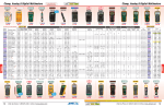
Digital Multimeter Guide
Mastech M9803R
Version 2008-Jan-1
Dept. of Electrical & Computer Engineering
Portland State University
Copyright © 2008 Portland State University
Digital Multimeter Guide
ECE Dept – Portland State University
1 – Basic Information
This guide provides basic instructions for operating the Mastech M9803R Bench Digital Multimeter. The
M9803R provides these features:
•
Multiple measurement functions:
DC & AC voltage, DC & AC current,
resistance, audible continuity test,
capacitance, frequency, diode test
•
True RMS capability
•
4 ½ digit backlit LCD display with 42 segment bar graph
•
Auto and Manual Range with data hold
•
RS232C computer interface
2 – Instrument Front Panel
Figure 1: Mastech M9803R front panel
Copyright © Precision Mastech Enterprises Co.
1
Digital Multimeter Guide
ECE Dept – Portland State University
LCD Panel
The LCD shows the measured value as numbers in the center of the display. In addition, a multi-segment
bar graph gives an analog representation of the value. At the bottom of the panel is a row of annunciators
that indicate the range mode, measurement unit (V, A, Ω, F, Hz), and multiplier (n, µ, m, k, M).
Power Switch
This switch controls the AC line input to the multimeter. It is located at the rear of the multimeter case.
Function / Range Selector Rotary Switch
The rotary switch selects which measurement function to perform. For DC and AC current
measurements, it also sets the range1.
The multimeter is turned off by rotating the switch to the OFF position. When the switch is in any other
position, the multimeter is turned on.
DC & AC current
(up to 10 A)
Multimeter OFF
AC voltage
DC voltage
DC & AC current
(up to 400 mA)
Selection
indicator
Resistance &
Continuity
Diode test
Capacitance
Frequency
Multimeter OFF
Figure 2: Close-up view of the rotary switch
Copyright © Precision Mastech Enterprises Co.
1
Use a range that is just large enough to accommodate the maximum DC or AC current to be measured. As an
example, if the actual current is 15 mA, then the 40 mA range is optimal. The 4 mA range is too small, while the
400 mA range is too big. Note that 400 mA will work, but the 40 mA range has better resolution.
2
Digital Multimeter Guide
ECE Dept – Portland State University
Function Buttons
These buttons activate additional multimeter functions. Some often used buttons are:
•
BACKLIGHT – illuminates the LCD display.
•
FUNCTION SELECTOR
•
RANGE
•
When the rotary switch is set for Resistance & Continuity, pressing this button
toggles between Resistance mode and Continuity mode.
•
When the rotary switch is set for DC and AC current (A), pressing this button toggles
between DC mode and AC mode.
•
When the rotary switch is set for DC and AC current (mA), pressing this button
toggles between DC mode and AC mode.
RANGE – allows manual selection of the measurement range
Differences among Auto Range, Manual Range, and Fixed Range modes
In Auto Range mode, the multimeter automatically chooses the appropriate range for
measuring and displaying the data. In Manual Range mode, the user can step through
different ranges by pushing the RANGE button. In Fixed Range mode, the range is set
by the position of the rotary switch, so the RANGE button has no effect.
Function
DC Voltage
AC Voltage
DC & AC Current (A)
DC & AC Current (mA)
Resistance
Continuity
Capacitance
Frequency
Diode
Auto
√
√
Manual
√
√
Fixed
√
√
√
√
√
√
√
√
√
Table 1: Available range modes for each measurement function
Pressing the RANGE button selects the Manual Range mode. The “AUTO”
annunciator will turn off, and the “MANU” annunciator will turn on.
Each subsequent press of the RANGE button will change the range and update the
display.
Pressing the RANGE button for longer than one second will exit the Manual Range
mode and revert back to Auto Range mode. The “MANU” annunciator will turn off,
and the “AUTO” annunciator will turn back on.
Warning
When measuring current, always start at the highest range first and check the measured
value. If more resolution is needed, then gradually step down to lower ranges. Failure to
follow this procedure can lead to excessive current at the mA or A input terminals of the
multimeter and may blow the internal fuse.
3
Digital Multimeter Guide
ECE Dept – Portland State University
Input Terminals
External test leads are connected to the input terminals of the multimeter.
Figure 3: Close-up view of the input terminals
Copyright © Precision Mastech Enterprises Co.
o
VΩ
Ω╟Hz – Positive input terminal for all functions except current measurements
o
COM – Negative (ground) input terminal for all functions
o
A – Positive input terminal for both DC and AC current measurements up to 10 A
o
mA – Positive input terminal for both DC and AC current measurements up to 400 mA
3 – Test Leads
Test leads are insulated wires that connect the circuit or component being tested to the multimeter’s input
terminals. Two leads are required for all measurements. By convention, one lead is color-coded red
(positive input), while the other is color-coded black (negative or ground input).
One end of the test lead is plugged into an input terminal on the multimeter. The other end can be one of
a variety of test connectors. Popular choices include straight test probes, alligator clips, mini-grabbers,
and spade lugs.
Measuring DC/AC Current (A)
A
mA
COM VΩ
Ω╟Hz
Red
Black
Measuring DC/AC Voltage, Resistance,
Continuity, Capacitance, Frequency, Diode
A
mA
Measuring DC/AC Current (mA)
COM VΩ
Ω╟Hz
A
Black
Red
Red
Black
mA
Figure 4: Standard test lead connections for various measurements
4
COM VΩ
Ω╟Hz
Digital Multimeter Guide
ECE Dept – Portland State University
4 – Measurement Procedures
Measuring DC Voltage (V)
1. Attach test leads to the input terminals.
DC (V)
Black → COM , Red → VΩ╟Hz
2. Turn the rotary switch to: V
3. Choose either Auto Range (default) or Manual Range.
4. Connect the test leads in parallel across the test circuit.
–
Black
Circuit
Red
Red probe tip → positive side of circuit
Black probe tip → negative side of circuit
+
5. Read the measured voltage.
Note: If the positions of the probe tips are swapped, the
measured value will have a negative sign.
Measuring AC Voltage (V)
1. Attach test leads to the input terminals.
AC (V)
Black → COM , Red → VΩ╟Hz
2. Turn the rotary switch to: V
Black
3. Choose either Auto Range (default) or Manual Range.
4. Connect the test leads in parallel across the test circuit.
Circuit
Red
5. Read the measured voltage.
Note: The M9803R displays the RMS (Root Mean Square)
magnitude of the AC waveform.
Measuring DC & AC Current (up to 10 A)
1. Attach test leads to the input terminals.
DC & AC
(A)
Black → COM , Red → A
2. Turn the rotary switch to: A
3. Use the FUNCTION SELECTOR button to set whether
DC or AC current will be measured.
4. Turn off power to the test circuit and then connect the
test leads in series with the circuit branch to be measured.
5. Turn on power to the circuit and read the measured current.
5
Circuit
Red
Black
Digital Multimeter Guide
ECE Dept – Portland State University
Measuring DC & AC Current (up to 400 mA)
1. Attach test leads to the input terminals.
DC & AC
(mA)
Black → COM , Red → mA
2. Initially, turn the rotary switch to: 400mA
3. Use the FUNCTION SELECTOR button to set whether
DC or AC current will be measured.
Circuit
Red
Black
4. Turn off power to the test circuit and connect the test
leads in series with the circuit branch to be measured.
5. Turn on power to the circuit and read the measured current.
Note: If the value does not have enough resolution, then
use the rotary switch to progressively lower the
range setting to either 40mA or 4mA.
Measuring Resistance (Ω
Ω)
1. Attach test leads to the input terminals.
Resistance
Black → COM , Red → VΩ╟Hz
(Ω)
2. Turn the rotary switch to: Ω
Black
3. Choose either Auto Range (default) or Manual Range.
4. Turn off any power to the test device. Connect the test
leads across the resistor.
Red
5. Read the measured resistance.
Note: Measurement accuracy can be improved by using
REL mode (Refer to full Users Manual).
Measuring Capacitance (F)
1. Attach test leads to the input terminals.
Capacitance
Black → COM , Red → VΩ╟Hz
(F)
2. Turn the rotary switch to:
3. Choose either Auto Range (default) or Manual Range.
4. Turn off any power to the test device and discharge the
capacitor2.
Black
Red
5. Connect the test leads across the capacitor. If the capacitor
is polarized, be sure to follow the polarity markings.
6. Read the measured capacitance.
Note: Measurement accuracy can be improved by using
REL mode (Refer to full Users Manual).
2
The capacitor can be safely discharged by shorting a large resistor (e.g., 100 kΩ) across the two capacitor leads.
6
Digital Multimeter Guide
ECE Dept – Portland State University
Appendix 1 – Resolution and Accuracy
Range
400 mV
4V
40 V
400 V
Range
4V
40 V
400 V
DC Volts (mV DC)
Resolution
0.1 mV
1 mV
10 mV
100 mV
AC Volts (true rms, ac-coupled)
Resolution
1 mV
10 mV
100 mV
Accuracy (% rdg + digits)
± (0.3% rdg + 5d)
± (0.3% rdg + 2d)
± (0.3% rdg + 2d)
± (0.3% rdg + 2d)
Accuracy (% rdg + digits)
± (0.8% rdg + 5d)
± (1.2% rdg + 2d)
50Hz to 60Hz
45Hz to 1kHz
Range
4 mA
40 mA
400 mA
10 A
DC Current
Resolution
1 µA
10 µA
100 µA
10 mA
Accuracy (% rdg + digits)
± (0.8% rdg + 5d)
± (0.8% rdg + 5d)
± (0.8% rdg + 5d)
± (1.5% rdg + 10d)
Range
4 mA
40 mA
400 mA
10 A
AC Current
Resolution
1 µA
10 µA
100 µA
10 mA
Accuracy (% rdg + digits)
± (1.5% rdg + 5d) 45Hz to 400Hz
± (1.5% rdg + 5d) 45Hz to 400Hz
± (1.5% rdg + 5d) 45Hz to 400Hz
± (2% rdg + 10d) 45Hz to 400Hz
Range
400 Ω
4 kΩ
40 kΩ
400 kΩ
4 MΩ
40 MΩ
Resistance
Resolution
0.1 Ω
1Ω
10 Ω
100 Ω
1 kΩ
10 kΩ
Accuracy (% rdg + digits)
± (0.5% rdg + 5d)
± (0.5% rdg + 3d)
± (0.5% rdg + 3d)
± (0.5% rdg + 3d)
± (1% rdg + 5d)
± (1.5% rdg + 10d)
Range
4 nF
40 nF
400 nF
4 µF
Capacitance
Resolution
1 pF
10 pF
100 pF
1 nF
40 µF
10 nF
Accuracy (% rdg + digits)
± (2% rdg + 40d) in relative mode
± (2% rdg + 5d) in relative mode
± (2% rdg + 5d) in relative mode
± (2% rdg + 5d)
± (2% rdg + 5d) @ ≤ 20 µF
± (5% rdg + 5d) @ > 20 µF
Appendix 2 – References
[1] M9803R Bench Multimeter Users Manual, Precision Mastech Enterprises Co.
7