1
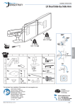
WorkFit-A, Single LCD Mount, LD
ASSEMBLY INSTRUCTIONS
ENGLISH
For local customer care phone numbers visit: http://contact.ergotron.com
For the latest User Installation Guide please visit: www.ergotron.com
User's Guide - English
Guía del usuario - Español
Manuel de l’utilisateur - Français
Gebruikersgids - Deutsch
Benutzerhandbuch - Nederlands
Guida per l’utente - Italiano
Användarhandbok - svenska
ユーザーガイド : 日本語
用户指南 : 汉语
Includes
Constant Force™
Technology
888-45-298-W-02 rev.G • 01/15
1 of 14
Warning: Because mounting surface materials can vary widely, it is imperative that you make sure mounting surface is strong enough to handle mounted product
and equipment.
Adjust the height of your desk (or chair and footrest) to allow the keyboard to lower to your sitting elbow height for ergonomic computing.
Caution:
To avoid the potential to pinch cables it is important to follow the cable routing instructions in this manual. Failure to follow these
instructions may result in equipment damage or personal injury.
Arm lowers along an arc.
Pull Arm toward you as
you lower from the
highest position.
Arm lowers along an arc. Pull arm towards you as you lower from the highest
position.
827-975
A+B+C < 20 lbs (9.1 kg)
5 - 15 lbs
A
(2.3-6.8 kg)
B
< 5 lbs
ENGLISH
(2.27 kg)
C
< 2 lbs
(0.9 kg)
0.78"-2.56" (20-65mm)
Important! You will need to adjust this product after
installation is complete. Make sure all your equipment
is properly installed on the product before attempting
adjustments. This product should move smoothly and
easily through the full range of motion and stay where you
set it. If movements are too easy or difficult or if product
does not stay in desired positions, follow the adjustment
instructions to create smooth and easy movements.
Depending on your product and the adjustment, it may take
many turns to notice a difference. Any time equipment is
added or removed from this product, resulting in a change
in the weight of the mounted load, you should repeat these
adjustment steps to ensure safe and optimum operation.
0.78"-2.56" (20-65mm)
0.5"-2.5" (13-64mm)
20˚
5"
(127 mm)
10˚
20"
(508 mm)
360˚
85˚
888-45-298-W-02 rev.G • 01/15
2 of 14
Set Your Workstation to Work For YOU!
Learn more about ergonomic computer use at:
www.computingcomfort.org
To Reduce Fatigue
Breathe - Breathe deeply through your nose.
Blink - Blink often to avoid dry eyes.
Break • 2 to 3 minutes every 20 minutes
• 15 to 20 minutes every 2 hours.
Height Position top of screen slightly below eye level.
Position keyboard at about elbow height with wrists flat.
Distance Position screen an arm's length from face—at least 20” (508mm).
Position keyboard close enough to create a 90˚ angle in elbow.
Angle Tilt screen to eliminate glare.
Tilt the keyboard back 10° so that your wrists remain flat.
A
1x
2
1x
C
1x
D
E
F
1x
1x
M5 x 8mm
1x
1x
M3 x 6mm
8x
M4 x 10mm
4x
2x
3
M4 x 10mm
M4x16mm
1x
4
4x
2x
M6 x 45mm
1x
1x
5
6
7
8x
8mm
1x
1x
4 mm
1x
1x
1x
1x
1/4”
2x
M5 x 35mm
1/4"
888-45-298-W-02 rev.G • 01/15
3 of 14
ENGLISH
1
B
1
Arm Extension and Desk Size:
The keyboard tray is designed to extend over the edge of your desk. You can expand the extension of the arm if
you need to based on your desk size. To determine if you need to expand your arm extension, refer to the 4 desk
dimensions below:
CLAMP
9.5"
(250 mm)
GROMMET HOLE
6
CAUTION: Base must be completely on desk surface.
Failure to follow these instructions may result in
equipment damage or personal injury.
9.5"
(250 mm)
Grommet hole can
be located anywhere
along this arch.
6
ENGLISH
12"
(300 mm)
12.75"
(320 mm)
10"
(260 mm)
10"
(260 mm)
12.75"
(320 mm)
CLAMP
CLAMP
With Expanded Arm Extension
1
2
3
4
To expand the arm extension, follow instructions on
next page.
12.75"
(320 mm)
GROMMET HOLE
Top View
GROMMET HOLE
With Expanded Arm Extension
To expand the arm extension, follow instructions on next page.
9.5"
(250 mm)
9.5" (250 mm)
5
18"
(460 mm)
5
16"
(410 mm)
12.75"
(320 mm)
Grommet hole can
be located anywhere
along this arch.
12.75"
(320 mm)
16"
(410 mm)
12.75"
(320 mm)
Top View
888-45-298-W-02 rev.G • 01/15
4 of 14
How to expand the arm extension.
a
b
c
180˚
base using the provided 4mm
hex wrench.
180˚
d2 Flip the base around (turn d3 Re-insert the 4 screws and tighten
180 degrees.
with the 4mm hex wrench.
4 mm
888-45-298-W-02 rev.G • 01/15
5 of 14
ENGLISH
d1 Remove the 4 screws at the
d
2
CLAMP
a
DESK THICKNESS
ENGLISH
GROMMET HOLE
4 mm
4 mm
0.78"-1.78" (20-45mm)
1.70"-2.56" (43-65mm)
b
4 mm
c
1x
1x
8mm
1/4”
1/4"
d 1x
1x
CAUTION: Bolt must be
centered in hole.
888-45-298-W-02 rev.G • 01/15
6 of 14
3a
2x
M6 x 45mm
4 mm
ENGLISH
b
c
2x
M5 x 35mm
WARNING!
Screws must be tightened to keep
product secure. Failure to follow these
instructions will create an unstable
situation and may result in equipment
damage or personal injury.
888-45-298-W-02 rev.G • 01/15
7 of 14
4
a
1x
b
c
2x
ENGLISH
M4x16mm
888-45-298-W-02 rev.G • 01/15
8 of 14
5a
b
M5 x 8mm
ENGLISH
6
1x
4 mm
1x
M3 x 6mm
0°
4x
M4 x 10mm
4x
M4 x 10mm
888-45-298-W-02 rev.G • 01/15
9 of 14
7
8
4x
1x
1x
4x
ENGLISH
M4 x 10mm
9
NOTE: Leave enough slack in cable to allow full range of motion.
Caution:
To avoid the potential to pinch cables it is important to follow the cable routing instructions in this manual. Failure to
follow these instructions may result in equipment damage or personal injury.
8x
1x
888-45-298-W-02 rev.G • 01/15
10 of 14
10
Adjustment Step
Important! You will need to adjust this product after installation is complete. Make sure all your equipment is
properly installed on the product before attempting adjustments. This product should move smoothly and easily
through the full range of motion and stay where you set it. If movements are too easy or difficult or if product
does not stay in desired positions, follow the adjustment instructions to create smooth and easy movements.
Depending on your product and the adjustment, it may take many turns to notice a difference. Any time
equipment is added or removed from this product, resulting in a change in the weight of the mounted load, you
should repeat these adjustment steps to ensure safe and optimum operation.
a
1
ENGLISH
1/4”
1/4"
8mm
Increase Lift Strength
If the mounted weight is too heavy or
this product does not stay up when
raised, then you'll need to increase
Lift Strength:
2
Decrease Lift Strength
If the mounted weight is too light or
this product does not stay down when
lowered, then you'll need to decrease
Lift Strength:
3
888-45-298-W-02 rev.G • 01/15
11 of 14
b
8mm
1/4”
1/4"
Increase Lift Strength
If the mounted weight is too heavy or
this product does not stay up when
raised, then you'll need to increase
Lift Strength:
Decrease Lift Strength
ENGLISH
If the mounted weight is too light or
this product does not stay down when
lowered, then you'll need to decrease
Lift Strength:
c
Increase Friction
If this product moves too easily from
side-to-side, then you'll need to
increase friction:
Decrease Friction
If this product is too difficult to move
from side-to-side, then you'll need to
decrease friction:
888-45-298-W-02 rev.G • 01/15
12 of 14
d
8mm
1/4”
1/4"
Increase Friction
If this product moves too easily from
side-to-side, then you'll need to
increase friction:
Decrease Friction
If this product is too difficult to move
from side-to-side, then you'll need to
decrease friction:
1/4”
1/4"
Increase Friction
If this product moves too easily from
side-to-side, then you'll need to
increase friction:
Decrease Friction
If this product is too difficult to move
from side-to-side, then you'll need to
decrease friction:
f
4 mm
Increase Friction
If this product moves too easily from
side-to-side, then you'll need to
increase friction:
Decrease Friction
If this product is too difficult to move
from side-to-side, then you'll need to
decrease friction:
888-45-298-W-02 rev.G • 01/15
13 of 14
ENGLISH
e
8mm
f
Angle Setting Adjustment
1
Loosen these two screws.
2
Loosen or tighten this bolt to adjust tilt to desired angle.
4 mm
ENGLISH
Tighten to tilt up.
Loosen to tilt down.
3
After desired tilt is achieved, retighten these
two screws to secure.
WARNING!
Screws must be tightened to keep product secure.
Failure to follow these instructions will create an
unstable situation and may result in equipment
damage or personal injury.
© 2015 Ergotron, Inc.
888-45-298-W-02 rev.G • 01/15
14 of 14