1
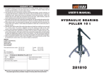
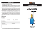
??? CARD
WARRANTY
1. KH Trading machines and tools are covered by 6/24 months warranty, starting on the date of
purchase, as described in the Civil Code (proof of purchase or invoice receipt must be
enclosed with the warranty card when making a claim).
2. This warranty does not cover defects caused by unprofessional handling, machine overloads, not
complying with instructions contained in this manual, using accessories that are not approved,
unauthorized repair, regular wear and tear and damages occurred during transport. Further, this
warranty does not cover parts and accessories such as the motor, carbon brushes, seals and
hot-air operated parts and parts that need to be changed regularly.
3. If the repair is to be found as not covered by the warranty policy, all costs including the repair and shipping to and from the repair centre will be paid by the customer, according to valid price list. See www.
4. When making a claim, you must present the warranty card, showing the date of the purchase, the
serial number of the machine, vendor stamp and signature of sales clerk, as well as the proof of
purchase receipt.
5. Warranty claim shall be made at the vendor shop where you bought your machine or you may mail
it to a service centre. The vendor is obligated to fill out the warranty card (date of sale, serial
number, vendor stamp and signature). All these information must be filled in at the time of sale.
6. The warranty period will be extended for the period of time for which the machine has been in the
service centre possession. If the repair or defect is not covered by the warranty policy, all costs including
the repair and shipping will be paid by the owner of the machine / tool. We recommend sending the
machine in its original packaging. Please, also enclose brief description of the defect with the packaging.
7. Before sending the machine for repair, clean it thoroughly. If the received machine is dirty, it may
be rejected by the service shop or you may be charged a cleaning fee.
USER'S MANUAL
METAL SHEET BENDING
MACHINE W 2.0 × 1 000
SERVICE
Logistic centre Klecany
Topolová 483
250 67 Klecany
Czech Republic
Claim department phone number: 266 190 156
266 190 111
Fax:
260 190 100
http://www.KHnet.cz
Email: [email protected]
Product:
Type:
T-mobile: 603 414 975
O2:
601 218 255
Vodafone: 608 227 255
METAL SHEET BENDING MACHINE W 2,0 × 1 000
Serial number (product series):
373004
Date of manufacture:
Repair centre notes:
Date of sale, stamp, signature:
373004
Without the correctly filled warranty card or without proof of purchase receipt, including
the product type (invoice, purchase receipt) no warranty claim will be processed.
Dear customer. Thank you for purchasing metal sheet bending machine from KH Trading, s.r.o.
Our company is ready to offer you our services - before, during and after you buy our product.
If you have any question, comment or idea, please contact our business centre. We will do our best to address
your comment or question in timely matter.
Before first use, please read this manual carefully. It is your responsibility to study all instructions,
necessary for safe use and operation and to understand all risks that may be involved during the use
of power machines.
WARNING! Do not try to use this machine before reading this entire manual and before you know
how to handle it. Keep this manual for future reference.
Pay special attention to safety instructions. Not complying with safety rules may cause injury to the
operating person or to people standing by or it may cause damage to the machine or to the work
piece.
Pay special attention to safety notes and safety labels on the machine.
Never remove or damage them.
Please, write information such as the invoice number
and the number of the sale receipt here in this box.
DESCRIPTION
This type of machine is used for sheet bending made of carbon-steel, metal or similar materials that have
comparable material density and physical properties. The maximum allowed width is 1,000 mm and maximum
thickness up to 2 mm.
TECHNICAL SPECIFICATION
Maximum sheet width . . . . . . . . . . . . . . . . . . . . . . . . . . . . . . . . . . . . . . . . . . . . . . . . . . . .1,000 mm
Maximum thickness . . . . . . . . . . . . . . . . . . . . . . . . . . . . . . . . . . . . . . . . . . . . . . . . . . . . . . . . .2 mm
Bending angle range . . . . . . . . . . . . . . . . . . . . . . . . . . . . . . . . . . . . . . . . . . . . . . . . . . . . . .0 - 135°
Side adjustment . . . . . . . . . . . . . . . . . . . . . . . . . . . . . . . . . . . . . . . . . . . . . . . . . . . . . . . . . .30 mm
Longitudinal tilt . . . . . . . . . . . . . . . . . . . . . . . . . . . . . . . . . . . . . . . . . . . . . . . . . . . . . . . . .50° - 24°
Range of rear stopper . . . . . . . . . . . . . . . . . . . . . . . . . . . . . . . . . . . . . . . . . . . . . . . . .200 - 400 mm
Dimensions (LxWxH) . . . . . . . . . . . . . . . . . . . . . . . . . . . . . . . . . . . . . . . . . . . . . .162 × 60 × 127 cm
Gross weight . . . . . . . . . . . . . . . . . . . . . . . . . . . . . . . . . . . . . . . . . . . . . . . . . . . . . . . . . . . . .490 kg
The accuracy of instructions, graphs and information contained herein, depends on the printing date. Due to
continuous product improvement, the manufacturer reserves the right to change technical parameters of the
product, without prior customer notification.
COMPENSATING WEIGHT
HOLDING LEDGE
BODY OF HOLDING
LEDGE
BENDING LEDGE
PRESS CONTROL
TURN HANDLE
BASE
BODY OF BENDING
LEDGE
BENDING LEDGE
ADJUSTMENT
SCREWS
BEND
HANDLE
STAND
2
REPAIR AND MAINTENANCE REPORT
Report and maintenance report:
DATE
REPAIR AND MAINTENANCE REPORT
SERVICE SHOP
???
SAFETY PRECAUTIONS
• This device may be used by a qualified person, 18 years or older who has been
trained in work and environmental safety procedures.
We recommend placing work safety regulations notices at your workshop:
Self-adhesive safety symbols labels used with your machine:
Read manual before use
Use protective gloves
Caution! Danger of being caught by
machine moving parts
Use protective clothing
Danger of bodily injuries
Place the self-adhesive safety labels on conspicuous place on your machine.
Symbols used in this manual
Warning!
This symbol informs you about the risk of personal injury or damage to the machine
or materials.
Warning!
Risk of damage.
Note:
Additional information.
General instructions
• Plastic packaging materials pose danger to children and animals.
• Make sure you know how to control your tool or machine and that you are familiar with its operating
procedure. Know the hazards that may occur, if not used correctly.
• If other person is using this machine make sure that he knows how to safely operate this equipment and
that he is familiar with hazards and risk that may occur, if not used correctly.
• Pay special attention to safety notes and safety labels on the machine. Never remove or damage them.
If the warning label becomes unreadable, please contact your vendor.
• Keep your working place clean. Dirty and disorganized workplace may cause accidents.
• Never work in tight spaces or in purely lit rooms. Make sure the floor is solid and stable and that you can
move around easily. Always keep stable posture.
• Keep focusing and use common sense. Do not continue working if you cannot pay attention.
3
•
•
•
•
•
•
•
•
•
•
•
•
•
•
•
•
•
•
•
•
•
•
•
•
•
•
Maintain your tools clean and in safe working conditions.
Handles must be kept free of grease and dirt.
Make sure no children, unauthorized persons or animals have access to your workshop.
Never put your hands or legs inside the working area.
Never leave your machine unattended during operation.
Use only for purposes for which it has been designed.
Use personal protective gear such as safety goggles, ear protection, respirator, safe working shoes etc.
Do not overreach, use both hands.
Never work under the influence of alcohol or other drugs.
Do not use the machine/tool if you feel dizzy or week.
Any modifications or improvements to the machine are strictly prohibited. If you discover any cracks or
damages to the machine, do not use.
Never perform any maintenance during operation.
If you see any unusual sign or hear any strange sound, switch of the machine immediately.
Do not forget to remove all wrenches and/or screwdrivers from the machine.
Before use, make sure all screws are tightened securely.
Perform maintenance regularly. Before use make sure the machine is in good working conditions
and without any damage.
Use only original spare parts during repairs.
Using accessories or extension pieces not approved by the manufacturer may cause injuries.
Use this machine only for work that could be handled by it. Do not overload tools, accessories or the
machine. For large work volume use more powerful machine.
Do not overload the machine. Measure the work load in such way, so it could be done with comfortable
speed. Damages due to machine overload are not covered by the warranty policy.
Do not expose to extremely high temperature or direct sunlight.
This machine is not designed for use in humid environments or under water.
If you are not using your equipment, store it in a dry and locked place, out of reach of children.
Before use, inspect all safety elements and make sure they work as designed. Make sure all moving parts
are in good working conditions.
Inspect all parts for cracks and damages. Make sure movable parts are not stuck and set properly.
Also take into consideration other conditions that may have a negative effect on the proper function of
your machine.
If not stated otherwise in this manual, all damaged parts and safety elements must be repaired or changed.
Bending and cutting operations
• Do not use your machine for metal sheet cutting with thickness, width and strength higher than the
maximum allowed values as described in the technical parameters.
• Do not use for thermally processed or hardened materials.
• Do not touch the conical toothed gears and the bending ledge during work. Severe injuries may occur.
• Always have the work piece securely fastened and use extreme caution when releasing or handling.
Assembly
• Do not use the machine unless completely assembled.
4
MATERIAL AND PART CHART
Position.
01
02
03
04
05
06
07
08
09
10
11
12
13
14
15
16
17
18
19
20
21
22
23
24
25
26
27
28
29
30
31
32
33
34
35
36
37
38
39
40
41
42
43
44
45
Name
Body of the holding ledge
Base
Body of the bending ledge
Stand
Connecting rod (left and right)
Angle measuring gauge
Balancing weight
Nut
Stopper shifting pole
Fixing head
Rest piece
Screw with hexagonal head
Hexagonal nut
Enclosed nut
Holding ledge
Upper ledge
Screw with hexagonal head
Hexagonal nut
Stopper shifting pole
Guiding screw (left, right)
Connecting ring
Connecting shaft
Conical toothed gear
Connecting shaft
Conical toothed gear
Connecting shaft
Bending ledge
Handle extension
Connecting rod
Pole
Handle
Distance ring
Handle connecting shaft
Hexagonal nut
Safety pin
Safety pin
Screw with hexagonal head
Seal
Screw with hexagonal head
Safety pin
Screw with hexagonal head
Screw with hexagonal head
Hexagonal nut
Screw with hexagonal head
Hexagonal nut
9
ASSEMBLY DRAWING
ASSEMBLY
• First, make sure that the machine is properly packed and that the packaging material is in good
conditions. If no defect is found, open the box and inspect its contents for completeness. Use the
enclosed part listing. If you discover any part missing or damaged, contact our office immediately and let
us know what is missing or what the problem is. That way you cover yourself against possible damages
or losses.
Specify the machine type, technical parameters and serial (model) number.
• Read the user's manual carefully.
• Remove all protective coatings and dirt and clean the working surfaces with suitable rust-preventive solution.
• Install the machine according to the enclosed instructions.
• Based on your installation requirements, mount the machine to the floor or to a special stand. Make sure
to comply with all safety rules and regulations. (Special stand is not supplied with your machine).
• To ensure comfortable material handling make sure to keep a space around the machine at least 1.5 m
wide.
• Make sure the surrounding area is well lit to prevent improper operation and injuries of the operation
personnel.
• Clean and lubricate the pressure lubricating caps with suitable grease. Clean any spilled grease.
• Lubricate the trapezoidal screws and sliding surfaces with suitable dust deterrent solution.
• Try if the handle turns easily all around.
• If not so, do not use excessive force.
• Find what the reason is and fix it.
• Turn the bending ledge and make sure that it is not touching the fixed ledge.
• If the ledge is touching the fixed ledge do not move it any further and follow the instructions further below.
OPERATION
Fastening the metal sheet
• Turn the handle counter clockwise. The conical gears on both sides will move the guiding screws.
The holding ledge will move upwards opening a space between the base and the holding ledge.
• Place the sheet in the machine so the part that will be bent is facing the bending ledge.
• Turn the handle clockwise until the holding ledge holds the sheet down securely.
• Perform the bending operation.
Setting an equal pressing (holding) force along the entire length of the holding ledge.
WARNING
IF THE SHEET IS NOT HELD DOWN PROPERLY ALONG ITS ENTIRE LENGTH, DO NOT USE EXCESSIVE
FORCE ON THE TURN HANDLE.
• If the sheet is not held properly along its entire length you will see it in the fold line. The part that is not
held properly will slide slightly. If that is the case, you must set the pressing (holding) force along the
entire length of the ledge.
• Turn the turn handle counter clockwise to lift the ledge up.
• Place pieces of material with the same thickness between the base and the holding ledge at both ends of
the ledge.
• Turn the handle clockwise to lower the ledge until at least one piece is securely fastened.
• Determine which one of the pieces is not held down. The side with the loose piece must be adjusted.
8
5
• On the side where you will perform the adjustment, remove the nut 14 safety studs that fit inside the nut
grooves (located on the upper desk )
• Release the lower nut.
• Tighten the upper nut until the loose piece is held down.
• Secure the position of the upper nut with the safety stud.
• Tighten the lower nut.
• Turn the turn handle to lower the holding ledge down and inspect if both pieces are securely held down.
• If they are not, repeat the above-described steps until the ledge securely holds down both pieces.
• If the setting is correct, place between the base and the holding ledge test piece whose length is as long
as the maximum allowed material width (an ideal scenario) and fasten it down by turning the turn handle.
• Perform bending test.
• If the material is not fastened in the middle of the holding ledge, it will get worn out over time and the
material will slip out of grip on one side eventually.
• If that happens you must set the grip again. Follow the steps described earlier.
• The adjustment must be repeated until the material is held down securely along its entire length.
• Finally, tighten the nuts and secure in place with the safety pins.
• When putting the safety pins inside, turn the nut so the holes in the nut and the threading are aligned.
If you cannot align both holes as needed, you may drill another hole in the threading to match the nut
holes.
Setting the thickness stoppers
• If you are working with many pieces with the same width you may set the thickness stop screws
(M16x100) that are located behind the holding ledge to prevent damages to the piece and to the
guiding bolt.
• Leave between the base and the bending ledge room that is equal to the thickness of the material to
fasten the piece securely but without damaging it.
Setting the position of the bending ledge
• During the bending process, the bending ledge must be lower than the ledge of the base. Otherwise
the material or the ledges may be damaged and the quality of the bend will be poor.
• Release the locking nuts 038 and slightly release screws 039 (M12x40) on both sides of the bending
ledge.
• Adjust both screws 037 on both sides of the connecting rod 05-F so the bending ledge is set lower than
the base ledge at least by the value equal to the material thickness.
• Tighten both screws 039 (M12x40) on both sides of the bending ledge and secure them in place by
tightening locking nuts 038.
• Slowly turn the bending ledge to make sure that the base ledge and the bending ledge are not touching
each other and that the gap between them is the same along the entire length.
• Place and fasten a test piece in the machine and perform a bending test.
• If the result is not satisfactory, repeat the adjustment steps as described above.
Setting the rear ledge
• You may set the rear stopper ledge in the rage between 200 mm - 400 mm.
• If you are working with many pieces of the same length, release the fixing heads on the rear ledge.
• Place the piece in the machine in the required position and secure it in place.
• Tighten the fixing heads on the rear ledge and start working.
6
Setting the angle stopper
• If you want to bend piece under 45° angle you must loosen the screw (M10x40) on the angle
setting stopper and set it to 135° angle, which is the additional angle needed to come up with the final
angle 45°. This value may be set on the rear ledge. When finished, tighten the screws (M10x50) and you
may begin your work.
MAINTENANCE
• Keep your tools clean. Dirt from tools may enter the inner machine mechanism and cause damages to the
tools or machine.
• When cleaning, pay special attention to the trapezoidal screws and bending ledges.
• Do not use aggressive cleaning solution or paint thinners to clean the machine. We recommend clean
and coat working surfaces with paraffin oil.
Lubrication
• Before lubricating any surface not equipped with lubrication caps or nipples, clean it first.
• Lubricate your machine regularly every day to ensure continuous and flawless operation.
• Use your hands to lubricate trapezoidal screws, toothed gears and all sliding surfaces that are not
equipped with lubrication caps.
• Refill all lubrication caps and nipples with suitable grease everyday.
• Before refilling grease, clean the lubrication caps thoroughly.
• Clean the overflowed or spilled grease with cloth.
DISPOSAL
When the operational life of your device is over, dispose off it in accordance with valid rules and regulations.
Your product is made of metal and plastic parts that may be recycled when separated.
1.
2.
Disassemble all parts.
Separate all parts according to the material they are made of (e.g. metals, rubber, plastics, etc.).
Take the separated parts to the recycling facility near you for further processing. Information about the
locations of recycling centres may be found at your local City office or throughout an Internet search.
CAUTION
If the machine breaks down, send it back to the vendor for repair for quick repair. Please, enclose brief
description of the defect. That makes repair easier. If the machine is still covered by warranty, enclose the
warranty card and proof of purchase receipt.
To prevent possible damages during shipping, packed the machine carefully or use the original packaging
material. After the warranty period expires, we repair your machine for a special price.
Note: Pictures and contents in this manual may slightly differ from the actual product or accessories.
It is due to continuous improvement of our products. Such small differences have no effect on the product
functionality.
7