1
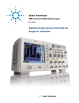
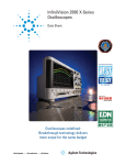
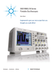
2064551/2062632
SMD REWORK STATION
User's Manual
Thanks for using our products, please read
this manual thoroughly before operation.
OPERATING INSTRUCTIONS
Note: In case of SOP, PLCC, desolder
it by using tweezers, etc.
QFP DE-SOLDERING
SPECIFICATION
●
Power Voltage
220V~ 50Hz
Power Consumption
560W(Max.)
Pump
Diaphragm Pump
Capacity
23L/min(Max.)
Hot Air Temperature
100℃ to 480℃
Outer Dimensions
7.4*5.3*9.6 inches
187*135*245mm(W*H*D)
Weight
4.5Kg (9.9 lbs)
After connection, the automatic blowing
function will start sending air through the
pipe, but the Heating Element remains cool.
●
●
Suit for most desoldering of SMD, such as
SOIC, CHIP, QFP, PLCC, BGA etc.
3
4
5
6
7
8
●
Indicator flickers denotes that heating
element is being heated up, when it
extinguishes denotes that temperature has
reached the setting one.
●
●
BEFORE OPERATION
●
Select the Nozzle that matches the
size of the IC.
Attach the Nozzle when both the Pipe and
the Nozzle are cool. Should either be warm,
check to make sure that the Temperature
Control Knobs set to1.
Turn the Power Switch off.
After the Power Switch is turned off, an
automatic blowing function begins sending
cool air through the pipe in order to cool
both the heating element and the handle. So
do not disconnect the plug during this
cooling process. In case you don't use the
unit for a ling time, disconnect the plug.
●
Loosen the screw on the Nozzle.
●
Attach the Nozzle.
Do not force the nozzle or pull on the edge
of the Nozzle by pliers. Also, do not
re-tighten the screw too tightly.
●
●
Remove any remaining solder.
After removing the IC, remove remaining
solder with a wick or de-soldering tool.
2
Preheat SMD.
●
Soldering
Washing
When soldering is completed, wash away the
flux.
●
by Hot air, it's also possible to cause the
defects such as solder balls, older
bridges. We recommend you to examine
the conditions of soldering sufficiently.
Remove the screws, slide the
tube.
Remove the 3 screws, which secure the
Handle and slide the cord tube.
●
Open the Handle.
Disconnect the ground wire sleeve and remove the
pipe. In the pipe. The quartz glass and heat
insulation is installed. Do not drop or miss it.
PRECAUTIONS
●
Disconnect the plug when you
don't use the unit for a long
time.
REPLACING THE HEATING ELEMENT
Note: While here is a merit to solder
●
Do not disassemble the pump.
When the power cord is connected into the
power supply, the unit has a little flow of
electricity, even the Power Switch is in off
position. So when you don't use the unit for
a long time, disconnect the plug.
Heat the lead frame evenly.
Before attach the nozzle, make
sure that both the heating tube
and the nozzle are cool down.
●
Remove the Heating Element.
Disconnect the terminal and remove the
Heating Element.
Caution High Temperature
Operation
●
Do not use the unit near ignitable gases,
paper, or other inflammable materials. Both
the nozzle and the heated air are extremely
hot and can cause painful burns. Never touch
the heater pipe or allow the heated air to
blow against your skin. Initially, the iron may
emit white smoke, but this will soon
disappear.
●
Note: After turn off the Power
Switch of about 1minute later, power
is automatically shut off.
●
Refer to the photo to preheat SMD.
Remove the IC.
Once the solder has melted, remove the IC
by lifting the plier.
●
Apply the solder paste.
Apply the proper quantity of solder paste and
install the SMD on the PCB.
Melt the solder.
Hold the iron so that the Nozzle is located
directly over, but not touching the IC and
allow the hot air to melt the solder. Be
careful not to touch the leads of the IC with
the Nozzle.
Temp. (℃) 100 130 190 250 310 380 440 480
●
Adjust the Air Flow and
Temperature Control Knobs.
●
Never drop or sharply joint the
unit.
The pipe contains quartz glass, which can
break if the unit is dropped or jolted sharply.
QFP SOLDERING
After adjusting the Air Flow and
Temperature Control Knob, wait for the
temperature to stabilize for a short period of
time.
CHART OF TEMPERATURE
2
Turn the Power switch on.
The Power Switch may be turned on at any
time while the automatic blowing function is
operating. Once the Power Switch is turned
on, the Heating Element will begin to warm
up.
USAGE
Temp. Knob 1
Plug the power cord into the
power supply.
●
Insert a new Heating Element.
Handle it with care. Never rub the Heating
Element wire. Insert a new Heating Element
and reconnect the terminal. Reconnect the
ground wire after replacing the element.
Assemble the Handle in the reverse order of
disassembly. Insert the Handle's projection
into the hole in the pipe.
Interchangeable Parts:
After use, be sure to cool the
unit.
After turning off the power switch, the unit
will automatically blow cool air through the
pipe for a short period of time .Do not
disconnect the plug during this cooling
process.
3
Number
Name
Specifications
1144
Heating Element
100V/ 250W
1146
Heating Element
110V/ 250W
1144A+
Heating Element
100V/ 250W
1146A+
Heating Element
110V/ 250W