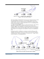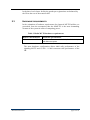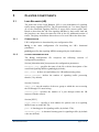
1
MVTS-based clusters Operator's Guide © Mera Systems Inc.. 2004 MVTS Session Border Controller Industry-grade cluster solution Document №: 1 Document type: User Guide Document status: Release Version 1.0.0 Date of issue: 08.09.2004 Responsible employee: Technical writer C o p yr igh t © 200 4 M era Sys tems Inc .. A l l r ig h ts r es er ve d . M er a S ys tems I nc . r es e r ves th e r i gh t t o c han ge a n y i n fo r ma t io n c o n ta ine d i n t h is d oc u men t w i tho u t pr io r no t ic e . COPYRIGHT INFORMATION T he in for ma tio n c on taine d in th is doc ume nt is the pro per ty o f Mera Sys te ms Inc. No pa r t o f th is p ub lica tio n ma y b e rep roduc ed or c op ie d in any fo rm or b y an y m ea ns - gr aph ic , e lec tro n ic or mec ha nica l i nc l ud ing p ho toc op y in g , r ec o r d ing , ta ping , or a n y o ther in fo rma tio n s torag e an d re trie val s ys te m - w i th ou t wr itte n co nsen t o f Mera Sys te ms Inc . No th ird pa r ty, org an iza tion or ind i vid ua l , is a u tho riz ed to gra nt s uch per mission . History of changes History of changes Date Version Author and description of changes 07/07/2004 Draft 08/09/2004 Release Technical writer. Modified after review by developers. 1. Description of the min_asr, min_acd parameters changed 2. Description of trust relationship between systems changed (security warning added) 3. Recommendations for single-server-cluster transition added 4. SIP-HIT mention introduced 29/06/2005 Release Technical writer. Modified the description of the stabdby redundancy scenario after developers’ recommendations 06.08.2005 Release azharkov: chapter “Document structure”, modified Hyperlinks to the table of references, inserted Index, removed List of tables, List of pictures, Table of references, added MVTS-based clusters Technical writer. Created on the basis of developer’s notes. Subject to overview and revision by the development team. page 3 of 21 Contents Contents 1 INTRODUCTION .......................................................................................................... 8 1.1 1.2 1.3 1.4 2 OVERVIEW.................................................................................................................. 10 2.1 2.2 2.3 3 DOCUMENT PROFILE .................................................................................................... 8 AUDIENCE ................................................................................................................... 8 NOTATIONAL CONVENTIONS ....................................................................................... 8 DOCUMENT STRUCTURE .............................................................................................. 8 GENERAL CONSIDERATIONS ...................................................................................... 10 WHAT IT TAKES TO SET UP AN MVTS-BASED CLUSTER ............................................. 10 HARDWARE REQUIREMENTS ...................................................................................... 12 CLUSTER CONSTITUENTS ..................................................................................... 13 3.1 LOAD BALANCER (LB).............................................................................................. 13 3.1.1 Configuration ..................................................................................................... 13 3.1.2 lb.cfg configuration file...................................................................................... 13 3.2 SIGNALING MVTS .................................................................................................... 14 3.3 MEDIA MVTS........................................................................................................... 16 4 STANDBY REDUNDANCY........................................................................................ 18 4.1 4.2 REDUNDANCY IDEOLOGY .......................................................................................... 18 TRUST RELATIONSHIP BETWEEN PRIMARY AND STANDBY SYSTEMS .......................... 18 APPENDIX 1: WHAT’S IN A TWO-LEVEL CLUSTER PACKAGE ......................... 20 APPENDIX 2: MISCELLANEOUS OPERATIONAL ISSUES ..................................... 21 SMOOTH TRANSITION FROM SINGLE-SERVER TO CLUSTER SOLUTION .................................. 21 HOW THE SIP-HIT TRANSCODER FITS IN THE CLUSTER MVTS........................................... 21 MVTS-based clusters page 4 of 21 List of Tables List of Tables Table 1 Typographic conventions used in the document......................................................... 8 Table 2 Media MVTS hardware requirements ...................................................................... 12 MVTS-based clusters page 5 of 21 List of Figures List of Figures Figure 1 Two-level MVTS cluster ......................................................................................... 11 Figure 2 Three-level MVTS-based cluster solution............................................................... 11 MVTS-based clusters page 6 of 21 Table of References Table of References Reference MVTS-based clusters Name of the document [1] “MVTS 3.1.0 User Manual” [2] “MVTS_Configuration” [3] “SIP-HIT system administrator guide” page 7 of 21 1 INTRODUCTION 1.1 DOCUMENT PROFILE This document is a working manual covering the peculiarities of the architecture, installation and operation of clustered versions of the MVTS session border controller produced by MERA Systems Inc. 1.2 AUDIENCE This guide is intended for System Administrators whose responsibility is to install, configure and operate the MERA VoIP Transit Softswitch (MVTS.) Users of this document are required to have an intimate knowledge of UNIXlike operating systems (Free BSD, Red Hat Linux) and working knowledge of the MVTS session border controller [1]. 1.3 NOTATIONAL CONVENTIONS The conventions used in this document are described in Table 1 below. Table 1 Typographic conventions used in the document 1.4 Example Convention Note: text Important information requiring special attention [N] Reference to some other document void Examples of source code, program output, logs, configuration files etc. Ulimit Names of programs or files call_radix= Courrier New, 11 pt is used to highlight names of parameters of configuration files and their sections DOCUMENT STRUCTURE Here is a brief synopsis of the chapters and appendixes in this document: Chapter 1: Introduction describes the purpose and the structure of this document. Chapter2: Overview gives coverage of the product clustered version, its purpose, considerations that might compel you to contemplate upgrading your switching capacity. In addition, the chapter provides general information about the hardware specifics of the product’s clustered version. Chapter 3: Cluster constituents leads you through the particulars of clustering the MVTS solution and explains operation and general MVTS-based clusters page 8 of 21 configuration of the system. Disregard section 3.1 if you operate a two-level cluster facility. Chapter 4: Cluster redundancy describes a method of setting up a standby server in support of your live-traffic system. The principles and algorithm of backing up the cluster version of the softswitch are entirely different from the way this is done for stand-alone platforms. MVTS-based clusters page 9 of 21 2 OVERVIEW 2.1 GENERAL CONSIDERATIONS Being a cost-effective solution the MVTS session border controller (SBC) installed on a platform whose computing power does not differ much from an average table-top system can handle but a limited number of simultaneous calls. As the carrier’s business grows the increased volume of traffic may require additional investment in the switching facility. To protect your initial investment in the switching capability and cope up with the scalability challenge the MVTS SBC is made clusterable. 2.2 WHAT IT TAKES TO SET UP AN MVTS-BASED CLUSTER Operation in a heavy traffic environment necessitates division of the major system functions (gatekeeper, RADIUS, signaling proxy, media proxy etc.). The roles of constituent MVTS systems within a cluster element change. The most resource-intensive process in terms of computing power is full proxy (signaling and media) operation. Therefore, pumping media traffic becomes the sole function of the computer which we call in what follows Media MVTS (MMVTS). At the same time all the gatekeeper, routing, billing and RADIUS procedures are now the job of the system referred to in this document as signaling MVTS (SMVTS). Since signaling, routing, billing and all associated tasks are less demanding from the standpoint of computing power one SMVTS can control several MMVTSs (reliably manageable fleet is three full proxies of 1500-2000 simultaneous calls capacity). Therefore a basic functional cluster element comprises two parts: signaling MVTS (SMVTS) in control of three media MVTSs (MMVTS) A block diagram of a cluster element is demonstrated in Figure 1 below MVTS-based clusters page 10 of 21 Figure 1 Two-level MVTS cluster Since the number of media MVTSs in the two-level cluster hierarchy is small the signaling MVTS is designed to evenly distribute traffic between the media systems. Such four-component layout (an SMVTS in control of three media systems) provides a cluster element that can serve as a building block for large-scale switching facilities. As a single signaling MERA can cope up with maximum three 1500 capacity MMVTSs, a growth in the population of media servers requires more signaling MERAs, and proliferation of signaling MVTSs entails introduction of dispatch control of some kind and changes in the intellect of the signaling MVTS which is now designed to work under the control of a Load Balancer (LB). Deployment of the Load Balancer to manage operational efficiency of the signaling MVTSs provides a three-level cluster version of the MVTS-based switching facility. With the only function of “giving orders” a single LB can control as many as 4-5 signaling MERAs. Figure 2 Three-level MVTS-based cluster solution MVTS-based clusters page 11 of 21 In the three-level cluster facility the gatekeeper registrations are balanced by the LB as the rest of the transit traffic. 2.3 HARDWARE REQUIREMENTS In the estimation of hardware requirements for clustered MVTS facilities we proceeded from the assumption that the MMVTS is the most demanding element of the system in terms of computing power. Table 2 Media MVTS hardware requirements MMVTS Performance Hardware specifications 2000 concurrent calls Dual Xeon Pentium IV 2.8GHz/2048Mb RAM/1 or 2Gb Ethernet ports The same hardware configuration allows 6000 calls performance of the signaling MVTS and 15’000 – 18’000 concurent calls performance of the LB. MVTS-based clusters page 12 of 21 3 CLUSTER CONSTITUENTS 3.1 LOAD BALANCER (LB) The main task of the Load Balancer (LB) is even distribution of signaling traffic among signaling MVTSs. The LB periodically (in 5 sec time) inquires all of the controlled signaling MVTSs to assess their current traffic load. Based on these data the LB sorts signaling MERAs by their traffic load and the least busy one always becomes the first in line for additional portion of traffic. The query mechanism allows the use of several LBs at the same time. 3.1.1 CONFIGURATION LB’s configuration is determined by two configuration files. lb.cfg is the main configuration file describing the LB’s functional parameters. pool.cfg specifies the signaling MERAs managed by the load balancer. 3.1.2 LB.CFG CONFIGURATION FILE The lb.cfg configuration file comprises the following sections of configuration parameters: Section [Administration] incorporates the configuration parameters: mvtspool_cfg= specifies the name of the file with the description of the controlled signaling MERAs (pool.cfg by default); mail_alert= defines an email address for LB malfunctioning alerts; waiter_threads= defines the number of signaling traffic processing threads (1 by default). Section [Console] admin_gid= sets the number of the user group to which the user accessing the LB through CLI must belong. console_port= specifies the number of a port through which the LB interacts with the console. Section [H323] local_address= specifies a local address for packets sent to a signaling MERA (same as in the MVTS); port= is listening port for signaling traffic (by default 1720); alternate_port= is alternate listening port for signaling traffic (by default value not defined). MVTS-based clusters page 13 of 21 Section [SNMP] The configuration parameters of this section are identical to those found in the [SNMP] section of a regular MVTS: local_port= contact_info= system_name= system_location= community= trap_community= trap_address= trap_port= trap_level= trusted_address= trap_enable= snmp_enable= trap_email= trap_email_cmd= trap_email_subject= trap_email_from= trap_email_period= 3.2 SIGNALING MVTS Operating a signaling MERA in a two-level cluster facility does not differ much from operating a common MVTS session controller with one minor exception – the signaling MERA runs as a signaling proxy only regardless of the settings that affect this operating mode. To terminate calls specify the media MVTS as an H323-to-H323 converter (field converter= in the [H323] section of the meraproxy.cfg file) for outbound calls only. Example: converter=media1/IP-address/port/2/1 Naturally, in the routing plan of the terminating gateway you will have to define via what converter (i.e. media MVTS) calls will be terminated. The configuration files of the signaling MVTS in a two-level cluster facility differ from those of a stand-alone MVTS in one section only. The section name is [Media]; it is included into meraproxy.cfg and features the following configuration settings: MVTS-based clusters page 14 of 21 [Media] address= min_asr= min_acd= call_radix= suspend_time= no_connect_suspend_time= mode= address= serves to specify the IP address and port of the media server. You can specify several address:port pairs on a line delimiting them by semicolons. For example: address/port=193.121.78.55:1720;193.121.78.58:1720 if you omit a port number the default port is 1720. min_asr= is the minimum acceptable ASR setting (see also field min_asr= in [2]). Dropping below the defined min_asr= value will suspend the media MVTS in question for the period set in suspend_time=. Valid values are integers in the 0 – 100 range. Example: min_asr=50 min_acd= sets the minimum acceptable ACD (Average Call Duration). Dropping below the min_acd= value will suspend the media MVTS for the period set in suspend_time=. Valid values are positive integers from 0 through 10000 (average call duration in seconds.) Example: min_acd=60 call_radix= serves to define the base (i.e number of calls) for ACD and ASR calculations (see also descrition of the call_radix parameter in [2].) Example: call_radix=300 suspend_time= sets the time (in seconds) for which the low-ACD or low ASR media server becomes suspended. Valid values are positive integers in the 0 to 86399 range (86399 seconds = 24 hours). The default value is 0. Example: suspend_time=600 MVTS-based clusters page 15 of 21 no_connect_suspend_time= serves to set for how long the media server will stay suspended in the absence of a TCP connect (seconds). Valid values are positive integers in the 0 to 86399 range (86399 seconds = 24 hours). Example: no_connect_suspend_time=300 mode= serves to control the system operating mode when media servers become inaccessible. Valid settings are 1 and 0. 1 means terminate calls with the target terminating entity when no media server is accessible 0 means terminate calls with the local error eNoMediaServer=400 when no media server is accessible code Example: mode=0 The SMVTS distributes calls between the media servers based on the actual MMVTS traffic load reestimated every second. 3.3 MEDIA MVTS The media MVTS (MMVTS) is intended for full proxying calls only. The functionality of the media MVTS has been reduced to indispensable austerity that would allow a pass-through for signaling traffic and media proxying. The media MVTS is devoid of the following capabilities: - interoperation with a remote gatekeeper; - gatekeeper functionality - interaction with RADIUS servers - call statistics - definition of routing rules With the only task of media proxying the MMVTS has but one configuration file meraproxy.cfg. The media MVTS extracts call termination addresses from Setups supplied by the signaling MERA. The signalling_proxy_address= parameter is the only configuration setting that distinguishes the [Administration] section of the meraproxy.cfg file of the media MVTS. This parameter serves to enter a list of addresses from which the media MVTS accepts calls. Use the semicolon character to delimit the list items. Consider an example of the meraproxy.cfg file for a media MVTS below: [Administration] MVTS-based clusters page 16 of 21 [email protected] # this is email local_address=* rtp_threads=1 call_threads=1 public_access=0 signalling_proxy_address=192.121.1.1;192.121.1.2 [Console] console_port=1730 admin_gid=0 billing_gid=0 support_gid=0 [H323] port=1720 [Debug] trace_level=3 level=3 no_empty=1 period=1:00:00 file=../debug/logs/ max_size=3000000 max_lifetime=100 max_file_size=200000 [Proxy] local_address=* MVTS-based clusters page 17 of 21 4 STANDBY REDUNDANCY 4.1 REDUNDANCY IDEOLOGY The redundancy of the system is accomplished by deployment of a standby control element (LB or SMVTS) that runs as a failover server ready to take over from the primary system at any moment. To ensure a smooth takeover from the primary system, should the latter fail, the standby system must be configured exactly as the primary platform. The takeover and failback scenario for the primary and failover systems is organized in the following way. Let us assume the primary server has three network interface cards and operates three IP addresses A1, A2, and A3 to handle (i.e. send and receive) traffic. The standby server must have the same quantity of NICs so that the operation addresses are equally accessible both on the primary host and on the failover system. At every single instance of the system operation, the addresses are up and active on one server only. During normal operation, addresses A1-A3 are active on the principal host only. At regular intervals (the period is configurable), the standby server attempts a TCP connect to all the three addresses. Failure of all connect attempts (the number of connect retries is configurable too) is the indication that the principal server is out of order. In this case, the failover server gets the same three IP addresses up on its NICs and assumes traffic. Once the main host is up and running again, it checks the IP addresses for activity and if the addresses are dormant, the principal server starts in a normal way. If the activity check is positive, the resurrected host sends the failover server (which handles traffic) a special command directed at the active IPs. Following this command, the failover server shuts down the operating IP addresses and goes to the standby mode. This done, the principal MVTS host gets the IPs up on its NICs and accepts traffic. All the necessary configuration parameters for implementing this redundancy layout you can find in the section [Redundancy] of the file of global system settings meraproxy.cfg. [2] 4.2 TRUST RELATIONSHIP BETWEEN PRIMARY AND STANDBY SYSTEMS Trust relationship enables remote access to the standby server with the root account privileges without the need to enter the access password. Trust relationship between computers is instrumental to allow remote execution of commands over ssh and make it possible to remotely start scripts that automate important administration procedures and operation tasks. MVTS-based clusters page 18 of 21 Let us assume there are two servers named master.com and backup.com. To establish trust relationship between the computers for remote access over ssh: Log on to the backup.com server using the root account and type the following commands at the console prompt: # ssh-keygen -t dsa This utility generates a secret and public key and writes them to the files /root/.ssh/id_dsa and /root/.ssh/id_dsa.pub respectively. During the dialogue with the ssh-keygen utility just press the 'Enter' key in response to all the questions of the application (while responding to the message "Enter passphrase (empty for no passphrase)" do not enter anything, just press the 'Enter' key). # scp /root/.ssh/id_dsa.pub [email protected]:/root/.ssh/authorized_keys2 The scp utility will copy the id_dsa.pub file from the backup.com server to the master.com server writing it to the file root/.ssh/authorized_keys2 and will ask for the root password for the master.com server. As a result, after typing ssh [email protected] you will get a backup.com remote terminal at the master.com server with root account permissions. Note: Establishing trust relationship between computers is a serious breach in security. Use this facility judiciously. Provide trust relationship only for the systems where it is absolutely necessary. MVTS-based clusters page 19 of 21 APPENDIX 1: WHAT’S IN A TWO-LEVEL CLUSTER PACKAGE mvts-2.1.8-Linux.tar.gz – signaling MVTS mmvts-Linux.tar.gz – media MVTS MIME-Lite-2.117.tar.gz – MIME mera_backup_watchdog.plx script) Lite rpms (required for the synchro.tgz – configuration synchronization script for the primary and failover system. MVTS-based clusters page 20 of 21 APPENDIX 2: MISCELLANEOUS OPERATIONAL ISSUES SMOOTH TRANSITION FROM SINGLE-SERVER TO CLUSTER SOLUTION To ensure a smooth single-server-to-cluster transition with the minimum downtime of the system it is advisable to proceed as follows: 1. Deploy and configure your new cluster facility 2. Add the cluster MVTS as a gateway and dialpeer in your singleserver configuration 3. Make a routing rule to divert part of the traffic to the cluster facility and see how your new installation operates 4. When positive that the cluster deployment is ready to fully take over remove the single-server facility from service by deactivating the networking IP address on the single-server MVTS and getting it up on the cluster MVTS For that purpose get down the networking IP on the old MVTS server by typing at the command prompt: ># ifconfig eth0 down get up the IP address on the cluster MVTS server by typing at the command prompt: ># ifconfig eth0 inet xxx.xxx.xxx.xxx netmask yyy.yyy.yyy.yyy ># ifconfig eth0 up Note: Do not forget to make appropriate IP address changes in the scripts that ensure interoperation of the primary and standby servers in the failover scheme HOW THE SIP-HIT TRANSCODER FITS IN THE CLUSTER MVTS The SIP-HIT converter is deployed on the media MVTS level. Load balancing between SIP-HITs is impossible in the current versions of the MVTS cluster solution (implementation pending) and the protocol converter has to be rigidly linked to the assigned terminator. For MVTS-based clusters more information on the SIP-HIT module, see [3]. page 21 of 21