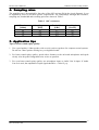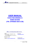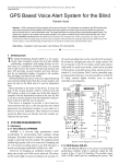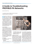
1
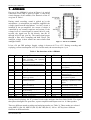
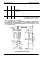
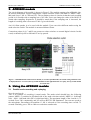
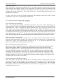
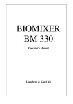
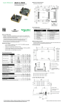
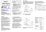
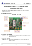
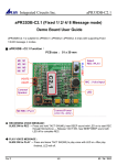
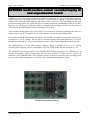
INTEC DATA SHEETS
APR9600 sound recording module
APR9600 multi-section sound recorder/replay IC
and experimental board
APR9600 is a low-cost high performance sound record/replay IC incorporating flash analogue
storage technique. Recorded sound is retained even after power supply is removed from the
module. The replayed sound exhibits high quality with a low noise level. Sampling rate for a 60
second recording period is 4.2 kHz that gives a sound record/replay bandwidth of 20Hz to 2.1 kHz.
However, by changing an oscillation resistor, a sampling rate as high as 8.0 kHz can be achieved.
This shortens the total length of sound recording to 32 seconds.
Total sound recording time can be varied from 32 seconds to 60 seconds by changing the value of a
single resistor. The IC can operate in one of two modes: serial mode and parallel mode.
In serial access mode, sound can be recorded in 256 sections. In parallel access mode, sound can be
recorded in 2, 4 or 8 sections. The IC can be controlled simply using push button keys. It is also
possible to control the IC using external digital circuitry such as micro-controllers and computers.
The APR9600 has a 28 pin DIP package. Supply voltage is between 4.5V to 6.5V. During
recording and replaying, current consumption is 25 mA. In idle mode, the current drops to 1 µA.
The APR9600 experimental board is an assembled PCB board consisting of an APR9600 IC, an
electret microphone, support components and necessary switches to allow users to explore all
functions of the APR9600 chip. The oscillation resistor is chosen so that the total recording period
is 60 seconds with a sampling rate of 4.2 kHz. The board measures 80mm by 55mm.
APR9600 Experimental board
1
Intec Associates Ltd.
INTEC DATA SHEETS
APR9600 sound recording module
1. APR9600
Pin-out of the APR9600 is given in Figure 1. A typical
connection of the chip is given in Figure 2 (This is the
circuit diagram of the module). Pin functions of the IC
are given in Table 1.
During sound recording, sound is picked up by the
microphone. A microphone pre-amplifier amplifies the
voltage signal from the microphone. An AGC circuit is
included in the pre-amplifier, the extent of which is
controlled by an external capacitor and resistor. If the
voltage level of a sound signal is around 100 mV peakto-peak, the signal can be fed directly into the IC
through ANA IN pin (pin 20). The sound signal passes
through a filter and a sampling and hold circuit. The
analogue voltage is then written into non-volatile flash
analogue RAMs.
Figure 1 Pin-out of APR9600
It has a 28 pin DIP package. Supply voltage is between 4.5V to 6.5V. During recording and
replaying, current consumption is 25 mA. In idle mode, the current drops to 1 µA.
Table 1 Pin-functions of the APR9600
Pin
Name
Functions
Pin
15
SP-
Speaker, negative end
16
VCCA
Analogue circuit power supply
-M3
Select 1 st section of sound or serial
mode recording and replaying
control (low active)
Select 2nd section or fast forward
control in serial mode (low active)
Select 3 rd section of sound
17
MICIN
4
5
6
-M4
-M5
-M6
Select 4 th section of sound
Select 5 th section of sound
Select 6 th section of sound
18
19
20
MICREF
AGC
ANA-IN
7
OSCR
21
ANA-OUT
8
-M7
Resistor to set clock frequency. See
Table 3 for details
Select 7th section of sound or IC
overflow indication
22
STROBE
9
-M8
23
CE
10
11
-BUSY
BE
24
25
MSEL1
MSEL2
12
13
14
VSSD
VSSA
SP+
Select 8 th section of sound or select
mode (see Table 2)
Busy (low active)
=1, beep when a key is pressed
=0, do not beep
Digital circuit ground
Analogue circuit ground
Speaker, positive end
Microphone input (electret type
microphone)
Microphone reference input
AGC control
Audio input (accept a signal of
100 mV p-to-p)
Audio output from the
microphone amplifier
During
recording
and
replaying, it produces a strobe
signal
Reset sound track counter to
zero/ Stop or Start / Stop
Mode selection 1 (see Table 2)
Mode selection 2 (see Table 2)
26
27
28
EXTCLK
-RE
VCCD
External clock input
=0 to record, =1 to replay
Digital circuit power supply
1
-M1
2
-M2
3
Mane
Functions
During sound replaying, the IC’s control circuit reads analogue data from flash RAMs. The signal
then passes through a low-pass filter, a power amplifier and output to an 8 to 16 Ohm speaker.
There are different sound recording and replaying modes (see Table 2). These modes are selected
using MSEL1 (Pin 24), MSEL2 (Pin 25) and –M8 (Pin 9). –M1 to –M7 keys have different
functions in different modes.
2
Intec Associates Ltd.
INTEC DATA SHEETS
APR9600 sound recording module
Table 2 Modes and selection of modes
MSEL1
MSEL2
-M8
Function Keys
0
1
0 or 1
1
0
0 or 1
1
1
1
1
1
1
0
0
1
-M1, -M2 to select 1st and 2nd
sound tracks. CE to stop
-M1 to –M4 to select a sound
track, CE to stop
-M1 to –M8 to select a sound
track, CE to stop
-M1 to –M8 to select a sound
track, CE to stop
-M1 and CE
0
0
0
-M1,-M2 and CE
Functions
Parallel mode, 2 sections, 30 seconds for each
Parallel mode, 4 sections, 15 seconds for each
Parallel mode, 8 sections, 7.5 seconds for each
Pressing and hold down a key from –M1 to M8 to
play the selected sound track repeatedly
Serial mode, allow up to 256 sound tracks to be
recorded and played. Sound tracks are played from
1st to N in order after –M1 is toggled. Press CE to
play from the 1 st sound track.
Serial mode, Press –M1 to replay one sound track.
Toggle –M2 once to move to the next sound track.
Press CE to play sound from the 1 st sound track
Notes:
• RE=0 to record sound. RE=1 to replay sound
• Press -M1 to -M8 once to replay a sound track. Press the key again to stop replaying the track
• Press and hold –M1 to -M8 continuously, the corresponding track will be replayed repeatedly
• During recording, -M1 to M8 should be pressed while the sound is being recorded. Releasing
the key terminates recording.
Figure 2 Typical connections of the APR9600
3
Intec Associates Ltd.
INTEC DATA SHEETS
APR9600 sound recording module
2. APR9600 module
The circuit diagram of the module is shown in Figure 2. The module consists of an APR9600 chip,
an electret microphone, support components, a mode selection switch (-RE,MSEL1, MSEL2 and –
M8) and 9 keys (-M1 to –M8 and CE). The oscillation resistor is chosen so that the total recording
period is 60 seconds with a sampling rate of 4.2 kHz. Users can change the value of the ROSC to
obtain other sampling frequencies. It should be noted that if the sampling rate is increased, the
length of recording time is decreased. Table 3 gives the details.
An 8-16 Ohm speaker is to be used with the module. Users can select different modes using the
mode selection switch. The module is measured 80mm×55mm.
Connection points (0-8, C and B) can connect to other switches or external digital circuits. In this
cased, on-board keys M1 to M8 and CE are by-passed.
Figure 3 APR9600 module with connector details (to record in parallel mode, the switch setting should be same
as displayed above. To record, the top switch should be on the right-hand side. To replay, the top switch should
be on the left)
3. Using the APR9600 module
3.1 Parallel mode recording and replaying
Record sound tracks
This is an example of recording 8 sound tracks. The mode switch should have the following
pattern: MSEL1=1(switched to left-hand side of the mode selection switch), MSEL2=1 (left-hand
side). –M8=1 (left-hand side). RE=0 (right-hand side). The maximum length of the 8 tracks is 7.5
seconds. Press –M1 continuously and you will see BUZY LED illuminates. You can now speak to
the microphone. Recording will terminate if –M1 is released or if the recording time exceeds 7.5
seconds. Similarly, press –M2 to -M8 to record other sound tracks.
4
Intec Associates Ltd.
INTEC DATA SHEETS
APR9600 sound recording module
Replay sound tracks
Now make RE=1 (switched to Left-hand side of the mode selection switch) while keep other
switches at the same location. Toggle –M1 to –M8 (press key and release) causes a particular sound
track to replay once. While the sound is playing, press the same key again or press CE key will
terminate the current sound track. Press other key while a sound is being played causes a new
sound track to be played.
If a key from –M1 to -M8 is pressed continuously, the particular sound track will be played
continuously. Press CE to stop playing the sound track.
3.2 Serial mode recording and replaying
Record sound tracks sequentially
This is an example of recording sequential sound tracks. The mode switch should have the
following pattern: MSEL1=0(switched to right-hand side of the mode selection switch), MSEL2=0
(right-hand side). –M8=1 (left-hand side). RE=0 (right-hand side). Press CE first to reset the sound
track counter to zero. Press and hold –M1 down and you will see BUZY LED illuminates. You can
now speak to the microphone. Recording will terminate if –M1 is released or if the recording time
exceeds 60 seconds (in this case you will run out the memory for your next sound track). Press –M1
again and again to record 2nd, 3rd , 4th and other consecutive sound tracks. Each sound track may
have different lengths, but the accumulated length of all sound tracks will not exceed 60 seconds.
Replay sound tracks sequentially
Now make RE=1 (switched to Left-hand side of the mode selection switch) while keep other
switches at the same location. Toggle –M1 (press key and release) causes the 1st sound track to be
played once. Toggle –M1 again and again will play the 2nd, 3rd, 4th and other consecutive sound
tracks. Press CE to reset the sound track counter to zero.
Record sound tracks with forward control
This is an example of recording sound tracks with forward control. The mode switch should have
the following pattern: MSEL1=0(switched to right-hand side of the mode selection switch),
MSEL2=0 (right-hand side). –M8=0 (right-hand side). RE=0 (right-hand side). Press CE first to
reset the sound track counter to zero. This mode is rather similar to the above sequential sound
recording. The only difference is that after –M1 is pressed and released, the sound track counter
does not increment itself to the next sound track location. To move to the next sound track, –M2
should be toggled. So if –M1 is not toggled again and again without toggling –M2, sound will be
recorded at the same sound track location.
Replay sound tracks with forward control
Now make RE=1 (switched to Left-hand side of the mode selection switch) while keep other
switches at the same location. Toggle –M1 (press key and release) causes the 1st sound track to be
played once. Toggle –M1 again and again will still play the 1st sound track. Once –M2 is toggled,
the sound track counter is incremented and the next sound can be played. Press CE to reset the
sound track counter to zero.
5
Intec Associates Ltd.
INTEC DATA SHEETS
APR9600 sound recording module
4. Sampling rates
The sampling rate is determined by the value of the OSC resistor (R8 in the circuit diagram). It can
be adjusted by users to suit their specific requirements. The relationships amongst the resistance,
sampling rate, bandwidth and recording period are shown in Table 3.
Table 3 OSC resistances
OSCR resistance
[kOhm]
44
38
24
Sampling rate
[kHz]
4.2
6.4
8.0
Bandwidth
[kHz]
2.1
3.2
4.0
Recording time
[Second]
60
40
32
5. Application tips
Tips for better sound replay quality:
1. Use a good quality 8 Ohm speaker with a cavity such as speakers for computer sound systems.
Do not use a bare speaker which gives you degraded sound.
2. For better sound replay quality, speak with a distance to the on-board microphone and speak
clearly. Also keep the background noise as low as possible.
3. For even better sound replay quality, use microphone input or Audio Line In input. If Audio
Line In is used, the amplitude of input signal should be < 100 mV p-p.
6
Intec Associates Ltd.