1
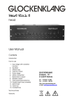
Heart-Rock
Poweramp
User Manual
Contents
Introduction
How to use
1.
2.
3.
4.
Power switch
Power connection
Input
Speaker output
GLOCKENKLANG
Eimterstr. 147
D-32049 Herford
Tel +49-5221-51506
Fax +49-5221-108755
http://www.glockenklang.de
e-mail: [email protected]
Technical Data
Warranty
Thank you for choosing the
GLOCKENKLANG Heart-Rock poweramp.
You have purchased an exquisite piece
of equipment, which was designed after
the most modern technical aspects.
Attention!
Handling
Do not drop the amp. Do not use
excessive force when activating switches
and dials.
Care
To activate your additional 3 years
warranty, you should send in the enclosed
warranty card.
Please enter the serial number of your
amplifier and the date of purchase and
send it to :
Use a soft, clean and dry cloth only to
clean the amplifier. Do not use aggressive
chemicals to clean the housing. Do not
use compressed air to clean the housing.
You may carefully vacuum the air intake
and exhaust areas from time to time to
remove loose dust accumulation.
Glockenklang
Eimterstrasse 147
D-32049 Herford
Germany
Please, keep this User Manual for
future references
or email to: [email protected]
General instructions
This serves as a measure to ensure
excellent customer service in the
future.
For your safety
Please read the following instructions
carefully. These tips will ensure long and
trouble free operation of your new
GLOCKENKLANG product.
Your Heart-Rock poweramp´s special
features:
Power amp protection circuit:
The power amp is short circuit , high
temperature, and DC voltage
protected. In case of high
temperature or DC current, the yellow
"Protect" LED will come on.
Operational restrictions
Do not operate the amplifier under the
following conditions:
•
•
•
•
In direct sunlight
In extremely dirty or dusty places
In extremely humid or wet places
Around heat emitting appliances
Caution: When rack mounting the
amplifier, make sure to leave adequate
room for ventilation. The unit needs this
ventilation space to adequately exhaust
it´s internally generated heat.
WARNING!
DO NOT OPEN!
NO USER SERVICEABLE PARTS INSIDE.
REFER SERVICING TO QUALIFIED
PERSONNEL.
Caution:
Please ensure adequate ventilation
when rack mounting the amplifier.
Leave a minimum of 5 mm space
below and above the amplifier. Make
sure that the air entry/discharge vents
at the left side of the housing are
unobstructed.
WARNING!
TO REDUCE THE RISC OF FIRE OR
ELECTRIC SHOCK,
SHOCK, DO NOT EXPOSE
THIS EQUIPMENT TO RAIN OR MOISTURE.
1.1 Power Switch
A/C Switch to turn on power to the unit.
Power On is indicated by a green LED.
1.2 Protect LED (red)
Illuminates when one of the protection circuits
activates. The speakers will be disconnected
with this light on.
1.3 Peak LED (yellow)
Illuminates when the power stage of the
amplifier begins to clip (overdrive). It warns of
overdrive and distortion.
2.1 A/C Mains cable and fuse
Mains cable with A/C connector. The fuse is
located in the small compartment above. The
fuse is rated at 6,3A/slo for 230V operation
and 12A/slo for 120V operation.
3.1 Poweramp In Jacks
Asymmetrical input connectors in parallel, will
be activated by the On switch above.
3.2 Ground Lift Switch
Separates signal ground from chassis ground
to eliminate hum and buzz, when connecting
other A/C connected gear. The switch
disconnects signal-ground from the housing.
The housing is still connected to the ground
(earth) by mains power-cable.
4.1 Speaker Out Connectors
4-pole speakon jacks for speaker connections.
These jacks are in parallel. Connect one 2,7
ohms or one 4 ohms and one 8 ohms or three
8 ohms cabinets here. The maximum power
rating is 1000 watts into 2,7 ohms, the
minimum permissible speaker impedance is
2,7 ohms. Connection is pins +1 and +2 hot,
pins –1 and –2 cold.