1
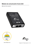
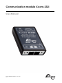
Communication module Xcom-232i User Manual Studer Innotec SA 2013 – V 1.2.0 51R Studer Innotec SA Xcom-232i COMMUNICATION MODULE XCOM-232I: USER MANUAL V 1.2.0 Copyright © 2013 Studer Innotec SA ABOUT THE SOFTWARE This document applies to software versions V1.4.2 or higher of the Xcom-232i. It is possible to check the currently used software version with the menu "Information on the system" or to update the product with the latest software version available on "www.studerinnotec.com/support". LEGAL NOTICE The use of Studer Innotec SA devices is the responsibility of the customer in all cases. Studer Innotec SA reserves the right to make any modification to the product without prior notice. PRODUCT RECYCLING The Xcom-232i conforms to the European directive 2002/95/EC on hazardous substances and does not contain the following elements: lead, cadmium, mercury, hexavalent chrome, PBB or PBDE. To dispose of this product, please use the service for collection of electrical waste and observe all applicable obligations according to the place of purchase. 2 V 1.2.0 User manual Studer Innotec SA Xcom-232i TABLE OF CONTENTS 1 INTRODUCTION .................................................................................................................................... 4 1.1 The communication module Xcom-232i ....................................................................................... 4 1.2 Conventions ........................................................................................................................................ 4 1.2.1 1.3 Symbols .................................................................................................................................. 4 Warranty and liability ........................................................................................................................ 4 1.3.1 Disclaimer of warranty ......................................................................................................... 4 1.3.2 Disclaimer of liability ............................................................................................................. 5 1.3.3 Compatibility ......................................................................................................................... 5 1.4 Safety precautions ............................................................................................................................. 5 1.4.1 Generalities ........................................................................................................................... 5 1.4.2 Warnings ................................................................................................................................ 5 2 EC DECLARATION OF CONFORMITY ................................................................................................. 6 3 INSTALLATION ...................................................................................................................................... 7 3.1 Mounting ............................................................................................................................................. 8 3.1.1 4 Connecting the communication bus ................................................................................ 8 DESCRIPTION OF THE COMMUNICATION MODULE XCOM-232I ..................................................... 9 4.1 Front ...................................................................................................................................................... 9 4.2 Back .................................................................................................................................................... 11 4.3 MicroSD card .................................................................................................................................... 11 5 RS-232 COMMUNICATION ............................................................................................................... 12 6 DATA LOGGER ................................................................................................................................... 13 6.1 Functioning........................................................................................................................................ 13 6.2 Analysis and visualization of the data with the Xtender data analysis tool or with the Xtender Matlab® data analysis ............................................................................................................... 13 7 SOFTWARE UPDATING ....................................................................................................................... 14 7.1 Updating process ............................................................................................................................. 14 8 DIMENSIONS ...................................................................................................................................... 15 9 MOUNTING ........................................................................................................................................ 16 User manual V 1.2.0 3 Studer Innotec SA Xcom-232i 1 INTRODUCTION 1.1 THE COMMUNICATION MODULE XCOM-232I Equipped with a serial port RS-232, the communication module Xcom-232i has been designed for remote communication with any SCADA (Supervisory Control and Data) system. This module also allows for data collection (energy consumption of a system, state of the auxiliary relays, input currents and voltages, etc...) on a MicroSD card thanks to the function “Data logger”. 1.2 CONVENTIONS 1.2.1 Symbols This symbol is used to indicate the presence of a dangerous voltage that is sufficient to constitute a risk of electric shock. This symbol is used to indicate a risk of material damage. This symbol is used to indicate information that is important or which serves to optimize your system. 1.3 WARRANTY AND LIABILITY During production and assembling, each Xcom-232i gets several controls and tests. They are carried out in full respect of fixed procedures. Each Xcom-232i is given a serial number allowing a perfect follow-up of the controls, in conformity with the specific data of every device. For this reason, it is very important to never remove the descriptive sticker bearing the serial number. The production, the assembling and the tests of each Xcom-232i are entirely carried out in our factory in Sion (CH). The warranty of this product depends on the strict following of the instructions in this manual. The warranty period for the Xcom-232i is 5 years. 1.3.1 Disclaimer of warranty No warranty will be applied for damages caused by handling, operation or actions that are not described in this manual. Damages arisen from the following events are not covered by the warranty: 4 Overvoltage on the device. Reverse polarity while connecting the battery. Liquid in the device or oxidation due to condensation. Failures due to a fall or to a mechanical shock. Modifications made without the explicit authorization of Studer Innotec SA . Nuts or screws partially or insufficiently tight during installation or maintenance. Damages due to atmospheric overvoltage (lightning). Damages due to transport or improper packaging. Disappearing of original marking items. V 1.2.0 User manual Studer Innotec SA Xcom-232i 1.3.2 Disclaimer of liability Installation, commissioning, use and maintenance of this device cannot be supervised by the company Studer Innotec SA . For this reason, we do not accept any liability for damages, costs or losses generated either by an installation that is not conforming to the prescriptions, by a defective operation or by poor maintenance. The use of this device is under the responsibility of the end-user. This device is neither designed nor guaranteed for the supply of life support applications or any other critical application with potential risks for human beings of for the environment. We shall assume no liability for patent infringement or other third party rights involved in the use of this device. 1.3.3 Compatibility Studer Innotec SA guarantees the compatibility of the software updates with the hardware for one year, starting from the date of purchase. The updates are no longer guaranteed beyond this date and a hardware upgrade may be required. Please contact your reseller for any additional information on compatibility. 1.4 SAFETY PRECAUTIONS 1.4.1 Generalities Carefully read all safety instructions before proceeding with the installation and commissioning of the device. Failure to follow these instructions might constitute a lethal physical danger but can also damage the functionalities of the device. Therefore this manual should always be kept close to the device. For any installation, the local and national norms and regulations in force must be strictly followed. 1.4.2 Warnings Wherever the installation, the person in charge of installation and commissioning must perfectly know the safety measures and the prescriptions in force in the country. Therefore, the whole maintenance must be carried out by a qualified staff. All components connected to this device must be conforming to the laws and regulations in force. Persons without a written authorization from Studer Innotec SA are forbidden to do any changes, modifications or repairs whatsoever. Regarding authorized modifications and replacements, only genuine components shall be used. This device is meant for indoor use only and must under no circumstances be exposed to rain, snow or any other humid or dusty environment. If used in motor vehicles, this device must also be protected against vibrations by absorbing components. User manual V 1.2.0 5 Studer Innotec SA Xcom-232i 2 EC DECLARATION OF CONFORMITY The communication module Xcom-232i described in this manual meets the requirements specified in the following EC directives and norms: Low voltage directive 2006/95/EC: EN 60950:2005 EMC directive 2004/108/EC: EN61000-6-1:2005 and EN61000-6-3:2006 RoHS directive 2002/95/EC CH - 1950 Sion, November 2011 Studer Innotec SA (R. Studer) Studer Innotec SA contact details Studer Innotec SA Rue des Casernes 57 CH - 1950 Sion Schweiz +41(0) 27 205 60 80 +41(0) 27 205 60 88 [email protected] www.studer-innotec.com 6 V 1.2.0 User manual Studer Innotec SA Xcom-232i 3 INSTALLATION The Xcom-232i is to be mounted as close as possible to the supervision or SCADA control system (PC, programmable logic controller, microcontroller) due to the more restrictive limits of the RS232 connection as compared with the Xtender communication bus. Figure 3.1: Connection schematics of the Xcom-232i (Example 1) Figure 3.2: Connection schematics of the Xcom-232i (Example 2) User manual V 1.2.0 7 Studer Innotec SA Xcom-232i 3.1 MOUNTING The Xcom-232i can be mounted directly on any support by means of the supplied fixing plate or on a smooth surface with double-side adhesive (see Figure 9 (p. 16)). 3.1.1 Connecting the communication bus The devices of the Xtender range are equipped with an own communication bus for data exchange, configuration and updating of the system. Connection is being made by linking the devices with the communication cables. One gets then a bus online where a link end must be activated on the devices on each end, to obtain the configuration of the Figure 3.3 . Each device is equipped with a switch offering to choose between open “O” and terminated “T”. The devices at the end of the line must be set on “T”. The others, receiving two communication cables, must be set on “O”. By default, the termination is not activated on each product of Studer Innotec SA . A wrong setting of the link ends can lead to an erratic running of the installation or impede its updating. Figure 3.3: Online communication bus of an Xtender system 8 V 1.2.0 User manual Studer Innotec SA Xcom-232i 4 DESCRIPTION OF THE COMMUNICATION MODULE XCOM-232I The communication module Xcom-232i consists of different parts with various functions. Here below, you will find the description of each part and of its function(s). 4.1 FRONT Front and isometric view of the Xcom-232i Key Description of the part Description of the function a Push button This button activates or deactivates the data logging functioni by pressing it for more than 3 seconds. When the data logging function is activated, the signalisation LED (b) is continuously green. b Bicoloured signalisation LED The signalisation LED indicates different functions by combining colour and blinking frequency. Below are the descriptions of each function. Updating process: During the Xcom-232i updating process (after insertion of a MicroSD card containing the updates), the signalisation LED blinks in red with a cyclical ratio of 50 % (Ton = 50 % | Toff = 50 %). The updating process can take between 3 and 15 minutes. During this period, it is possible that the signalisation LED does not meet exactly the cyclical ratio described above (Ton=50% |Toff=50%). The update process is completed as soon as the signalisation LED stops blinking red for at least 20 seconds. Error during update or back up of the data logger : If the Xcom-232i detects an error, the signalisation LED is continuously red (Ton = 100 % | Toff = 0 %). User manual V 1.2.0 9 Studer Innotec SA Xcom-232i MicroSD card full: If the Xcom-232i detects that the MicroSD card is full, the signalisation LED blinks in red with a cyclical ratio of 10 % (Ton = 10 % | Toff = 90 %). Data logging: When the data logging function is activated, the signalisation LED is green (Ton = 100% | Toff = 0 %). Communication (via RS-232 connection): When the communication via the RS-232 connection is active, the signalisation LED blinks in green with a cyclical ratio of 20 % (Ton = 20 % | Toff = 80 %). Insertion of the SD card: When inserting an SD card the signalisation LED is both red and green simultaneously for 1.5 seconds. In operation: The signalisation LED blinks in green twice when the Xcom-232i is operation and none of the above mentioned states is indicated. If several of the three states indicated by red LED light occur simultaneously, they will be displayed in the following priority order: Update processing Error during updating MicroSD card full If the two states indicated by green LED light occur simultaneously, the signal indicating communication via RS-232 connection is reversed (Ton=80% |Toff=20%). c Connectors CAN These connectors are used to connect the Xcom-232i with one or several Xtenders. d Switch for CAN termination This switch activates or deactivates the communication bus termination ii. The termination is by default activated on each product from Studer Innotec SA . i See Chapter 6: “Data logger” (p. 13) See Section 3.1.1 “Connecting the communication bus” (p.8) ii 10 V 1.2.0 User manual Studer Innotec SA Xcom-232i 4.2 BACK Back and isometric view of the Xcom-232i Key Description of the part Description of the function e RS-232 connector Connector for the RS-232 cable in order to enable data transmission to SCADA I systems. f MicroSD card reader Card reader in which to insert a MicroSD card that enables data logging ii and system updates iii. iSee Chapter 5: “RS-232 communication” (p. 12) See Chapter 6: “Data logger” (p. 13) iii See Chapter 7: “Software(s) updating” (p. 14) ii 4.3 MICROSD CARD All Xcom-232i are supplied with a MicroSD card (Micro Secure Digital). Inserted in the MicroSD card reader it allows among others: To update the whole system (Xcom-232i; Xtender; BSP)1 To restore parameters or settings Data logging The MicroSD card reader accepts the following type of cards: MicroSD and MicroSD HC. It is incompatible with MicroSD XC cards as well as cards with a capacity higher than 32 GB. 1 Update of a remote RCC-02/-03 or of another Xcom-232i must be done directly on the connected device. User manual V 1.2.0 11 Studer Innotec SA Xcom-232i 5 RS-232 COMMUNICATION The Xcom-232i is equipped with a serial port RS-232 which makes it possible to view and to program remotely one or several Xtenders operating in a system. This serial port allows to read all information that can be displayed on the remote control’s screen and also to modify the configuration parameters. An Xtender system can therefore be connected to various SCADA control and supervision devices (PC, programmable logic controller, microcontroller). Principle schematics of a typical application From a more technical point of view, the interface RS-232 allows for instance the data transmission with GSM modems, RS-232 bridges to TCP/IP or also with long distance converters RS-422. The specific protocol, easy, open and fully documented is available on request on www.studer-innotec.com/support (tab Protocol). 12 V 1.2.0 User manual Studer Innotec SA Xcom-232i 6 DATA LOGGER The communication module Xcom-232i offers a function that allows recording many electrical values of your system over a long time. With this function you can for instance follow the energy consumption and the battery voltage, or see the power cuts, the state of the auxiliary relays, the input currents and voltages, the output powers etc… This enables you to work out statistics, to check the system operation or its sizing, to verify the loads behaviour, to anticipate or to detect failures. The data logging function is by default deactivated on the Xcom-232i. 6.1 FUNCTIONING When the data logger is activated, a file is created every day at midnight on the SD card inserted in the remote control. This file contains data from all components within the Xtender system as well as recordings of the system’s electrical values, minute by minute. The file is registered in CSV format, which is read by most software. The file name integrates the date of measure in this format: LGyymmdd.csv. If there is no inserted MicroSD card, the daily data will be lost. Xcom-232i software updates will erase the daily data. 6.2 ANALYSIS AND VISUALIZATION OF THE DATA WITH THE XTENDER DATA ANALYSIS TOOL OR WITH THE XTENDER MATLAB® DATA ANALYSIS To facilitate the analysis of the information collected with the data logger function Studer Innotec SA offers two different analysis tools. The Xtender data analysis tool is of Microsoft® Excel® 2007 type which allows reading the CSV files generated by the Xcom-232i. This tool shapes and gathers the data of each Xtender and then displays them graphically. In this way the data become readable and understandable at a glance. A Matlab® script is also available. It enables to do analysis or to work out a possible simulation. These files can be downloaded for free on www.studer-innotec.com/support. Overview of an analysis with the “XTENDER Data Analysis Tool” User manual V 1.2.0 13 Studer Innotec SA Xcom-232i 7 SOFTWARE UPDATING In order to benefit from new functionalities make sure to update the Xcom-232i software from time to time as well as the software of the other integrated products of the Xtender system (Xtender inverter-chargers, BSP Battery status processors and VarioTrack MPPT solar charge controller). All software updates are available in the technical area of our website www.studerinnotec.com/support. 7.1 UPDATING PROCESS For more information about the updating process, please refer to the document “Updating procedure” available on: www.studer-innotec.com/support. Remember to turn off all Xtenders (putting them on “off”) before inserting the MicroSD card2 to carry out an update. If not manually performed, the updating process will automatically stop all Xtenders connected to the communication bus. To carry out an update, insert the MicroSD card (containing the latest software version) in the Xcom-232i module’s MicroSD card reader. Before starting the updating process, the system automatically checks the compatibility between the device and the software present on the MicroSD card. The MicroSD card must not be removed until the end of the updating process. If for some reason the updating process is interrupted, reinsert the SD card to let the process finish. The updating process can take between 3 and 15 minutes. During this period, it is possible that the signalisation LED does not respect exactly the cyclical ratio described3. The updating is finished once the signalisation LED stops blinking red for at least 20 seconds continuously. The updating of a remote control RCC-02/-03 or of another Xcom-232i must be done directly on the connected device. 2 3 Or SD card for the RCC-02/-03. See Chapter 4 : « Description of the communication module Xcom-232i » (p. 9) 14 V 1.2.0 User manual Studer Innotec SA Xcom-232i 8 DIMENSIONS Figure 8: Views of different sides with dimensions User manual V 1.2.0 15 Studer Innotec SA Xcom-232i 9 MOUNTING Figure 9: Mounting of the Xcom-232i 16 V 1.2.0 User manual Studer Innotec SA Xcom-232i User manual V 1.2.0 17 Studer Innotec SA Xcom-232i 18 V 1.2.0 User manual Studer Innotec SA Xcom-232i User manual V 1.2.0 19 Studer Innotec SA Rue des Casernes 57 CH -1950 Sion, Schweiz Tel: +41 (0) 27 205 60 80 Fax: +41 (0) 27 205 60 88 [email protected] www.studer-innotec.com