1
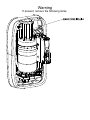
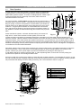
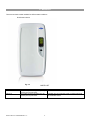
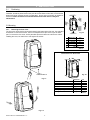
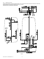
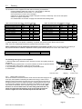
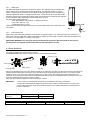
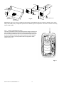
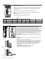
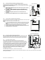
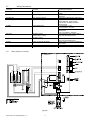
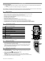
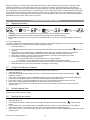
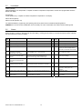
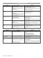
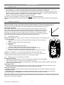
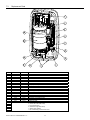
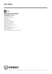
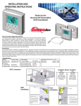
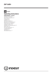
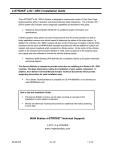
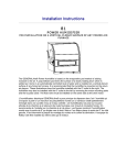
DS 50 / DS 50 LC
Elite Steam Residential Humidifiers
User manual
Revision 1.2
Warning
If present, remove the following items:
IMPORTANT WARNINGS
We wish to save you time and money!
We can assure you that the thorough
reading of this manual will guarantee
correct installation and safe use of the
product described.
BEFORE INSTALLING OR HANDLING THE HUMIDIFIER PLEASE CAREFULLY READ AND FOLLOW THE
INSTRUCTIONS AND SAFETY STANDARDS DESCRIBED IN THIS MANUAL AND ON THE LABELS ATTACHED TO
THE DS 50 / DS 50 LC. THIS HUMIDIFIER MUST BE INSTALLED BY A QUALIFIED HVAC, PLUMBING, OR ELECTRICAL
CONTRACTOR. ALL WARRANTIES ARE VOID IF INSTALLED BY A NON-TECHNICIAN.
CAUTION: ALWAYS DISCONNECT THE MAIN POWER BEFORE OPENING OR SERVICING THE HUMIDIFIER!
The Elite Steam produces non-pressurized steam by means of electrodes immersed in the water contained in the plastic
steam generator cylinder. Electric current passes through the water between the electrodes, heating the water into steam,
which is then used to humidify the air.
The quality of the water used affects the operation of this unit, so the Elite Steam may be supplied with untreated water, as
long as this is drinkable and not softened or demineralized. The water converted into steam is automatically replaced
through an electric fill valve. Periodically, based on the water quality, the unit will also drain some water to dilute the build-up
of minerals in the steam generator. In cases of high water mineral content, an activated carbon filter is series with a
particulate filter, no more than 5 microns is suggested.
This humidifier has been designed exclusively to directly humidify rooms or ducts, using a distribution system. The
installation, use and maintenance operations must be carried out according to the instructions contained in this manual and
on the labels applied internally and externally.
IMPORTANT: BEFORE beginning installation:
• Check for shipping damage to cartons. Mark the shipping waybill accordingly.
• Open cartons and check for any hidden damage. Mark the shipping waybill accordingly.
• Check packing slip to ensure all items have been received. Notify GENERAL FILTERS, INC. of any shortages or
damaged parts. You must notify General Filters, Inc. within 5 working days of any shortages.
CAUTION: ELECTRIC SHOCK HAZARD! The humidifier has components under power inside!
CAUTION: SCALDING HAZARD! The humidifier has hot parts (100°C/ 212°F)
WARNING: Install the humidifier out of the reach of children.
The humidifier must be installed in accordance with all local and national standards.
All service and/or maintenance operations must be performed by qualified personnel who are aware of the
necessary precautions and are capable of performing the operations correctly.
Disconnect the humidifier from the main power supply before accessing any internal parts.
The conditions of the environment and the power supply voltage must comply with the specified values listed on the
data label in the humidifier.
All other uses and modifications made to the humidifier that are not authorized by the manufacturer are considered
incorrect, and the manufacturer assumes no liability for the consequences of any such unauthorized use.
Please note that the humidifier contains powered electrical devices and hot surfaces.
WARNING: Your humidifier requires water to operate. Do NOT mount it above materials or machinery that could be
damaged if a leak occurs. General Filters, Inc. assumes no responsibility for consequential or inconsequential
damage as a result of any leaks.
Disposal of the parts of the humidifier: the humidifier is made up of metallic and plastic parts. All parts must be
disposed of according to the local standards on waste disposal.
DS 50 / DS 50 LC +030222065 Rev. 1.2
3
DS 50 / DS 50 LC +030222065 Rev. 1.2
4
CONTENTS
1.
1.1
1.2
1.3
HOW THE ELITE STEAM WORKS
6
BASIC OPERATION
CYLINDER LIFE
CALCULATING HUMIDITY LOAD
6
7
7
2.
MODELS
8
3.
INSTALLATION
9
3.1
3.2
3.3
3.4
3.5
3.6
3.7
4.
POSITIONING
MOUNTING
PLUMBING
STEAM DISTRIBUTION
POWER WIRING
CONTROL WIRING
WIRING CONNECTIONS:
9
9
11
12
15
15
17
START-UP
18
4.1
4.2
4.3
4.4
STARTUP CHECKLIST
THE ELITE STEAM CONTROLLER
STARTING THE ELITE STEAM
STARTING WITH A NEW CYLINDER
18
18
18
18
5.
OPERATING THE ELITE STEAM
19
5.1
5.2
5.3
5.4
5.5
5.6
DISPLAYING INFORMATION
CHANGING THE MAXIMUM PRODUCTION
ACTIVATING MANUAL DRAIN
RESETTING THE HOUR COUNTER
HUMIDISTATS
ALARMS
19
19
19
19
20
20
6.
TROUBLE SHOOTING
21
7.
MAINTENANCE
22
7.1
7.2
7.3
PERIODIC CHECKS
CYLINDER MAINTENANCE
REPLACEMENT PARTS
22
22
23
8.
TECHNICAL SPECIFICATIONS
24
9.
LIMITED WARRANTY
25
DS 50 / DS 50 LC +030222065 Rev. 1.2
5
1. HOW THE ELITE STEAM WORKS
1.1
Basic Operation
The Elite Steam is an electrode humidifier. It produces steam for humidification
3
by passing electric current through the water between metal electrodes in the
plastic steam generator cylinder. There are no heating elements. Steam output
is directly proportional to the conductivity of the water, and the amount of
electrode immersed in the water.
On a call for humidity, the Elite Steam controller will open the water fill valve (1)
and allow water to enter the cylinder. A flow restrictor (4) prevents the unit from
filling too quickly or with too much pressure. The water flows up the fill tube (2)
and into the fill cup (3). Water then flows over the dam in the fill cup (3), which
creates a 1” air gap to prevent backflow of contaminated water into the feed
lines, and through the fill tube (6) and into the bottom of the steam cylinder (5).
Any backflow or overflow of water travels through the overflow hose (13) to the
drain.
8
9
13
HL
7
2
5
6
12
DP
DT
EVF
4
1
As the water fills the cylinder, it will reach the electrodes (7) and current will
Fig. 1.a 11
10
begin to flow. As the water continues to fill the cylinder, the current will
increase, and this is monitored by an amperage transformer connected to one of the power wires and located on the
electronic controller. When the desired current is reached, the fill valve will close (1) and the water will then begin to warm
and produce steam. If the water reaches the cylinder full probes (9) or if current rises too much, the drain pump (11) will be
activated to drain away some water and reduce the current flow to acceptable levels. Note that, any time the drain pump is
activated, the tempering valve (10) will be opened for tempering the hot drained water down to 140 degrees F / 60 degrees C
in accordance to local and national standards.
Periodically, based on the incoming water conductivity, the unit will run drain pump (11) and drain some water to reduce the
mineral concentration. Every 120 hours the unit automatically drains to remove mineral sediment on the bottom of the
cylinder. A strainer (12) in the cylinder helps to prevent mineral debris from jamming the drain pump (11).
In case DS 50 / DS 50 LC remains powered but idle, i.e. without producing steam, for more than 72 hours (3 days), the
cylinder will be emptied to not have stagnant water inside.
If there is no water in the cylinder, there will be no current flow and no steam production. The electrodes do not burn out, but
they will eventually become completely coated with mineral and the cylinder will then need to be replaced. Cleaning cylinders
may cause electrode damage, therefore voiding its warranty. See 7.2.2 maintenance section on page 21.
No.
A
B
C
D
E
B
Description
Steam generator cylinder
User interface/display
On/Off, SET buttons
Fill & tempering valves
Drain pump
Tab. 1.a
C
A
D
E
Fig. 1.b
DS 50 / DS 50 LC +030222065 Rev. 1.2
6
1.2
Cylinder Life
1.2.1 Basics of the Steam Cylinder
The Steam Cylinder is the engine of the humidifier. As the humidifier operates water is evaporated and minerals are left
behind. Much of these minerals are removed through the cylinder drain. Some are deposited on the walls of the cylinder and
the cylinder electrodes. When a lower section of the electrodes develop a thick coating, the water level is raised to expose
clean electrode surface. Eventually minerals cover the electrodes’ entire length with a thick coating and little electrical current
can pass between them resulting in poor steam output. The humidifier can sense the low amperage and will display the E6
Cylinder Exhausted error code. There are several factors that influence cylinder life.
1.2.2 Water
Characteristics of water influence cylinder life and can vary greatly from place to place. Total mineral content of the water is
important. Equally important is what minerals are present in the water. Most water conditions result in flaky scale that
eventually fills the bottom of the cylinder until it can no longer function. Water with high silica content can result in a thin
glass-like coating on the electrodes that is highly insulating resulting in shorter cylinder life. Only cold non-softened tap
water is to be used. Water conductivity that is not matched to the correct cylinder will shorten cylinder life.
1.2.3 Water Filtration
Typically additional filtration of the incoming water supply is not necessary. If, however, mineral content is known to reduce
cylinder life excessively or if cylinder life proves insufficient then water filtration can be added. In most cases the addition of a
two element water filter can improve cylinder life. The filter should contain an activated carbon element and a particulate filter
element rated for 5 microns or less. Micron is a size measurement. The filter system should have a flow rate of at least
2 gpm. The activated carbon will absorb much of the mineral content while the particulate filter will catch any granular
material or sediment. It is important to remember that the increase in cylinder life will be accompanied by the need to replace
filter elements with each cylinder change.
1.2.4 Humidity Load and Cylinder Life
Humidity load demands have an effect on cylinder life. Normal installations where humidity capacity is properly sized require
only intermittent periods where full humidifier capacity is required. This allows the water level in the cylinder to be increased
only as electrode segments become insulated. This tends to maximize cylinder life.
Extraordinary installations that require constant operation at full capacity reduce cylinder life. The water level in the
cylinder is, on average, much higher, and the electrodes become completely insulated more quickly. Installations like this
may result in cylinder life of less than 1000 hours.
The importance of providing adequate humidifier capacity should not be underestimated.
1.2.5 Maximum Production
Another factor affecting cylinder life is the maximum production setting. A higher production
rate will result in a shorter cylinder life. For this reason DS50 or DS50LC units are preset from
the factory at 70%. Further reductions in Maximum Production will extend cylinder life.
See Figure 1.c.
Cylinder
Life
Fig. 1.c
100%
20%
1.2.6 Structures Under Construction
In high end construction projects, humidification is often required while the structure is being finished. Humidification is
necessary to protect and stabilize wood floors, trim and decoration. Humidification load, however, in an unfinished structure
may be five to eight times higher than when finished. Elite Steam humidifiers may be operated while construction is underway
but, reduced cylinder life is to be expected and budgeted for. Good practice dictates that the steam cylinders also be
replaced once the project is complete.
1.3
Calculating Humidity Load
1.3.1 Steps to Determine Humidity Load
Total Square Footage
x Average Ceiling Height
x Factor From Table 1.2
x 1.05 for each Fireplace
Humidity Load in lbs./hour
x 2.88 convert to gallons/day
Gallons per Day Humidity Load
Table 1.2 Pounds of Moisture / Hour / Cubic Foot *
Indoor Air
Temp °F
68
70
72
0.00015
0.00017
0.00019
Indoor RH%
40%
0.00018
0.00020
0.00022
* Based on .5 air charges per hour.
*Based on .5 air changes per hour.
DS 50 / DS 50 LC +030222065 Rev. 1.2
35%
7
45%
0.00021
0.00023
0.00025
50%
0.00024
0.00026
0.00028
Indoor Air Temp
◦
2. MODELS
There are two basic models available for different water conditions.
Duct Steam Injection
Fig. 2.a
MODEL LIST
PART NUMBER
DS 50
DS 50 LC
DESCRIPTION
Duct steam injections 58 gallons per day
(20 Lbs per hour) 220-240V
Duct steam injections 58 gallons per day
(20 Lbs per hour) 220-240V
DS 50 / DS 50 LC +030222065 Rev. 1.2
PARTS INCLUDED
Humidifier with Duct Mount Kit and Humidity GFX50 control.
Humidifier for Low Conductivity water. Includes Duct Mount
Kit and GFX50 control.
8
3. INSTALLATION
3.1
Positioning
The Elite Steam has been designed for wall mounting and, since it is an atmospheric steam
humidifier, should be placed close to the point where the steam will be used, to minimize the
steam hose length (and the amount of condensate). Do not mount on furnace, air handler or
ductwork. Certain clearances must be maintained around the unit for safety and
maintenance.
Clearance Dimensions
F
3.2 Mounting
3.2.1
Removing the front cover
The front cover is secured by two screws located in the bottom side of the unit. Use a phillips
screwdriver to remove the screws. The front is clasped with 2 clips on the top of the back
part. To remove the front cover, hold by the sides pivot the bottom out and lift cover. When
installing the cover, be careful not to over-tighten the screws.
Fig. 3.a
A
B
C
D
E
F
Millimeters
Inch
(150 mm)
6”
(150 mm)
6”
(150mm)
6”
(150 mm)
6”
(600 mm)
24”
max. 0.2°
Tab. 3.a
Unit Dimensions: Duct Units
screws M5x16
Fig. 3.b
SCREWS M5x16
Fig. 3.c
A
B
C
Weight empty
Weight packaged
Weight installed with water
Millimeters
445 mm
290 mm
790 mm
Kilograms
11kg
13kg
23kg
Inch
17.5“
12“
32“
Pounds
24 lbs
29 lbs
51 lbs
Tab. 3.c
Fig. 3.d
DS 50 / DS 50 LC +030222065 Rev. 1.2
9
3.2.2
Fastening to the wall
Drill the wall according to the drilling template supplied; then secure DS 50 / DS 50 LC firmly to the wall by the screws and
anchors supplied. Do not mount on furnace, air handler or ductwork.
Dimensions are in millimeters and [inches]
Fig. 3.e
DS 50 / DS 50 LC +030222065 Rev. 1.2
10
3.3
Plumbing
3.3.1
Water Characterisitc Requirements
The humidifier must be supplied with water with the following characteristics:
• pressure between 20psi and 110psi or 0.1 and 0.8 MPa (1 and 8 bar)
• temperature between 33°F and 104°F or 1°C and 40°C
• flow-rate minimum of 0.83 L/min or 0.22gpm
• hardness no greater than 40°fH (equal to 400 ppm³ of CaCO), conductivity: from 125 to 1250 μS/cm
• absence of organic compounds
• the characteristics of the water of supply must fall within the following limits:
LIMIT VALUES FOR LOW SALT CONTENT WATER
Units
Hydrogen ions (pH)
Specific conductivity (R,20°C)
Total dissolved solids (c R)
Dry residue at 180°C
Total hardness
Temporary hardness
Iron + Manganese
Chlorides
Chlorides
Chlorine residue
Calcium sulphate
μS/cm
mg/l
mg/l
mg/l CaC³O
mg/l CaC³O
mg/l Fe + Mn
ppm Cl
mg/Si2O
mg/l Clmg/l CaS4O
Min
7
300
(*)
(*)
150
=
=
=
=
=
=
LIMIT VALUES FOR LOW NORMAL WATER
Max
8.5
Units
Hydrogen ions (pH)
Specific conductivity (R,20°C)
Total dissolved solids (c R)
Dry residue at 180°C
Total hardness
Temporary hardness
Iron + Manganese
Chlorides
Chlorides
Chlorine residue
Calcium sulphate
(*)
(*)
400
200
0.2
30
20
0.2
100
μS/cm
mg/l
mg/l
mg/l CaC³O
mg/l CaC³O
mg/l Fe + Mn
ppm Cl
mg/Si2O
mg/l Clmg/l CaS4O
Tab.3.d
(*) Values dependent on the specific conductivity: in general: cR~=0.65*σR, 20°C; R180~=0.9*σR, 20°C
Note: There is no relationship between the hardness and conductivity of water.
Min
7
125
(*)
(*)
0
=
=
=
=
=
=
Max
8.5
500
(*)
(*)
200
150
0.2
20
20
0.2
60
Tab.3.e
Water Conductivity must be matched by specifications of the steam cylinder. Check or know the water conductivity of
the proposed site before installation. Replace the steam cylinder before startup if not correct. See Table 3.f right.
DS 50 / DS 50 LC models
DS50
DS50LC
Conductivity μS/cm
300-1250
125-500
Steam Cylinder
50-14
50-15
Tab.3.f
The following water types are not acceptable:
1. Softened water as this will lead to foam, electrode corrosion and greatly shortened
cylinder life.
2. Water containing disinfectants or corrosion inhibiters, as these are potential irritants.
3. Industrial water, boiler water or water from cooling circuits.
4. Any potentially chemically or bacteriologically contaminated water.
5. Heated water.
Water drain outlet
Fig. 3.g
Extension tube
3.3.2
Water Supply Connection
We recommend the connection between the fill valve and the water supply line by
a soft poly hose capable of absorbing the water hammering in order to avoid
damage to the fill valve itself. The water line may be routed through the back or
through the bottom of the unit. With poly tubing, a tubing support must be used
to prevent tubing collapse and leaks. The fitting then threads onto the fill valve
inlet located on the bottom of the humidifier using a 3/4” G connection. Note
that there is a strainer built into the fill valve fitting underneath the unit,
which will require periodic cleaning, so be sure to allow clearance for
access. Length of 1/4” tube should be kept to less than 1M or 3 ft.
Fill valve and filter
Water drain
Fig. 3.h
DS 50 / DS 50 LC +030222065 Rev. 1.2
11
3.3.3
Water Drain
The DS50 and DS50 LC requires a connection to a drain. The drain line may be routed out the
back or bottom of the unit using the included angle fitting. The drain line can be 1-1/4” PVC,
CPVC or polypropylene. The drain line is not glued or otherwise attached to the humidifier so it
must be supported by itself. A coupling should be used. The DS 50 / DS 50 LC includes a drain
tempering valve that runs whenever the drain pump runs and flushes cool water into the drain line
to insure the drain water temperature never exceeds 60°C or 140°F.
The drain water characteristics are:
• Drain Rate 26.8 liter per minute or 7.1 gallons per minute
• Connection 32mm or 1 1/4”
• Temperature 60°C or 140°F
NOTE: Drain line must be trapped under the unit to prevent flash steam from condensing in the
unit cabinet.
min. 5°
Fig. 3.i
4
5
3.3.4
Drain Connections
When using a rear outlet drain passing through drywall, we suggest using a 1 1/4” extension tube type SJ (see Fig. 3.i).
When using a bottom outlet drain, attach the included 90° fitting to the drain outlet. The drain outlet may be rotated. Then
connect a 1 1/4” trap adaptor to connect to drain pipe.
IMPORTANT WARNING: The drain pipe must be free without back pressure. We recommend an external antiflooding device not supplied to protect from faults of external hydraulic circuits.
3.4 Steam distribution
3.4.1
Duct steam injection
The maximum allowed duct static pressure is 2 in WC.
The DS 50 / DS 50 LC duct injection models include a 12” Steam Distribution Manifold
Mounting screws
Steam Inlet
Condensate drain
Flange gasket
Fig. 3.j
Select an accessible location on the duct, allowing at least 36” of straight duct (no elbows or obstructions) after the point where the
manifold will be installed and the clearances can be maintained as per the following drawings. See Fig. 3.j To mount the steam
manifold, cut a 2 ½” hole in the duct. Install the supplied o-ring or apply caulk to the mounting plate of the nozzle. Attach the
manifold to the duct using four sheet metal screws. Manifold must level or vertical to condensate outlet to the bottom. Connect the
steam and condensate hoses using the clamps supplied.
Note: End support bracket supplied only with 36” and longer manifold.
IMPORTANT:
DS 50
DS 50 LC
1. Allow 3 feet (1m) of straight duct downstream of the manifold for absorption of the steam.
2. Always allow 2 feet (0.6m) of straight duct upstream of the manifold. Turbulent air flow may require more.
3. Duct must be kept warm. Ducts in unconditioned spaces or over faulted ceilings must be well insulated to
prevent condensation.
Steam outlet dia. mm (in)
Max capacity kg/h (lb/h)
Steam distributor
7599 (50-09 steam distributor)
30 (1.2”)
9 (20)
Steam inlet dia. mm (in)
30 (1.2”)
DS 50 / DS 50 LC +030222065 Rev. 1.2
Max. capacity kg/h (lb/h)
15 (33)
12
Length mm (in)
300 (11.8)
Min 8”
Height >8”
Airflow
1000 cfm min.
Airflow
Airflow
1000 cfm min.
8” min
=
24” min
Upstream
1/3 Height
=
=
36”min
Downstream
Fig. 3.k
=
Airflow 1000 cfm min.
IMPORTANT: Allow 1 M ( 3 feet ) of straight duct downstream of the distributor pipes and nozzles for absorption of the steam.
Always allow 0.6M (2 feet) of straight duct upstream of the distributor pipes for evaporation of the steam. Turbulent air flow may
require longer lengths.
3.4.2
Return Condensate Connection
The return condensate hose from the manifold must be trapped. Coil the hose
into a vertical loop and secure it below the manifold. This water trap prevents
steam from being released into the hose. Insert the barbed fitting into the end
of the hose. Route the manifold drain hose through the top of the humidifier,
into the top of the fill cup. This is just above and to the right of the steam
cylinder. See. Fig. 3.l
Fig. 3.l
DS 50 / DS 50 LC +030222065 Rev. 1.2
13
3.4.3
Steam Hoses
IMPORTANT WARNING: NINETY PERCENT (90%) OF ALL OPERATION PROBLEMS ARE CREATED BY IMPROPER STEAM
PIPING FROM THE HUMIDIFIER UNIT TO THE DUCT DISTRIBUTOR PIPES.
To avoid these problems, remember one simple fact when running the steam hose: steam naturally flows up hill, and condensate
naturally flows downhill. Run the steam hose or piping to avoid any kinks, sharp elbows, or low spots that could collect or restrict the
flow of steam to the distributor pipe, or the flow of condensate back to the humidifier. Support the hose adequately to avoid sags.
The following diagrams are to provide you with some guidelines. If you have a situation you are unsure of, please contact Technical
Support for instructions. Contact information is printed on the back cover.
1,5 m (5 FT max.)
IF NO TRAP
20%
1,5 m (5 FT max.)
IF NO SLOPE
WITH TRAP
0,9 m (3 FT max.)
5%
TYPICAL INSTALLATION
WHEN UNIT IS ABOVE
THE DISTRIBUTOR PIPE
3 m (10 FT max.)
1,5 m (5 FT max.)
GENTLE BEND
20%
5%
20%
DRAINS
YES
20%
OBSTRUCTION
DRAINS
SUPPORTED STEAM HOSE
AND/OR COPPER PIPE
P - TRAP
NOTE: HEIGHT OF TRAPS MUST BE GREATER
THAN THE DUCT STATIC PRESSURE
NOTES:
• SLOPE PIPING UP IN DIRECTION OF STEAM FLOW AT 20% OR GREATER, WHICH MEANS 65,5mm x 305mm (2 1/2” PER FOOT);
• SLOPE PIPING DOWN IN THE DIRECTION OF STEAM FLOW AT 5% OR GREATER, WHICH MEANS 20mm x 305mm (3/4” PER FOOT);
• MAX. LENGTH OF RUBBER STEAM HOSE IS 3 m (10 FT).
• HEIGHT OF P-TRAPS MUST BE GREATER THAN THE DUCT STATIC PRESSURE.
NO SLOPE
SAG
NO SLOPE
KINKED
UNDRAINED
ELBOW
UNDRAINED
ELBOW
NO
NO TRAP
NO DISTRIBUTION
PIPE DRAIN
Fig. 3.m
IMPORTANT: Maximum length of rubber steam hose is 4m (12 feet.). Insulated copper tubing may be up to 6m(20feet) in
length. In all cases, minimize sharp bends and elbows. Use 2 - 45° elbows instead o f 90°s.
Hose inner diameter = 1.18” ( 30 mm); Hose outer diameter = 1-1/2” (40 mm).
Installation Items Included:
Steam hose, 8 feet
Condansate hose, 9 feet.
Hose Clamps, 4.
Steam manifold 12-inch.
Sheet Metal Screws, 4.
Water supply tube kit.
Fill Connector.
Code Valve Ball valve.
Pressure Switch.
GFX50 Humidistat.
Mounting Template.
DS 50 / DS 50 LC +030222065 Rev. 1.2
14
3.5 Power wiring
Check that the power supply voltage to be connected matches the value indicated on the rating
plate inside the electrical panel.
Insert the power and ground connection cables into the electrical panel compartment using the
strain reliefs supplied, and connect to the terminals. An external fused disconnect must be
installed. See Fig. 3.o
GROUND
TERMINAL BLOCK
All wiring must be in accordance with local, state and national electric codes.
NOTE: to avoid unwanted interference, the power cables should be kept separate from any
control wiring.
NOTE: Tolerance allowed on main voltage =-15% to +10%.
Connect power wires to the power terminal. See Fig. 3.p
Fig. 3.m
Model
Power supply
(single phase)
DS50
230Vac 50/60Hz
20 - 58
DS50LC
230Vac 50/60Hz
20 - 58
3.6
Steam Output
Steam Output
(lbs/hr – gal/day)
(kg/h)
POWER
(kW)
CURRENT
(A)
EXTERNAL
POWER WIRES
EXTERNAL FUSE (A)
OR BRAKER
9
6.9
30
AWG8
40 A / fast blow
9
6.9
30
AWG8
40 A / fast blow
Control wiring
The Elite Steam allows connection of any simple or automatic humidistat, and safety
devices such as high-limit humidistat, air flow proving switch, and remote on/off.
Included with the humidifier is the GFX50 Modulating Humidistat. The control will
increase a steam output if the humidity and setpoint are far apart. It will reduce output as
the humidity nears the setpoint. This allows for the most precise humidity control.
For on-off operation the humidifier is operated by the closing of a mechanical humidistat
H, or by the closing of a voltage-free remote contact, or alternatively by a combination of
both. A pressure switch is always used to confirm blower operation. The diagrams in the
figures show the connections to be made on the terminal block, in case of:
Fig. 3.r Operation performed by an external mechanical humidistat or control contact
and pressure switch;
Fig. 3.s Operation controlled by the included GFX50 Humidistat and pressure switch.
Fig. 3.o
Fig. 3.n
Pressure
switch
Fig. 3.r
Contact AB-AB:
• Closed: humidifier enabled to produce when humidistat closes closes or increases
voltage;
• Open: steam production is immediately stopped.
• The remote on/off contact is usually the pressure switch included with the humidifier.
The pressure switch NO and C terminals are connected to the AB-AB terminals.
• The remote on/off may include safety switches wired in series with the pressure
switch. These may include a high-limit humidistat a relay that closes when fan is
running or a downstream cooling coil contact that closes when coil is off.
Contact IN-GND:
If on-off operation is enabled (see section 5.1.1):
• closed: steam production starts if contact AB-AB is closed
• open: steam production is stopped after 5 sec.
Pressure
switch
MODULATING
HUMIDISTAT
Fig. 3.s
DS 50 / DS 50 LC +030222065 Rev. 1.2
15
2.
3.
4.
5.
4
ON
3
OFF
2
Elite Steam
OFF
1
DIP
GFX50 HUMIDISTAT
ON
3.6.1
Connect the GFX50 Humidistat for Modulating operation
Connect Elite Steam terminals 24V and GND to GFX50 terminals GO5 and G6
respectively. Do not reverse these connections. Connect GFX50 terminal A OUT 6
to Elite Steam terminal IN. See fig. 3.t.
NOTE:
1. MODULATING OPERATION requires Elite Steam signal type be changed,
ON
SEC. 5.1.1 page 19
The GFX50 is capable of ON-OFF operation. See the GFX50 manual.
The GFX50 is capable of Outdoor Temperature Compensation see the
GFX50 manual.
The GFX50 is designed to wall mount. It is not intended for duct
installation.
Reversing the 24V and GND leads will result in humidifier malfunction.
Fig. 3.t
E2 HUMIDISTAT
SNSR
HUM
2.
3.
4.
AC N
1.
AC L
3.6.2
Connect the E2 Humidistat ON-OFF Operation
Connect Elite Steam terminals 24V and GND to E2 terminals ACL, ACN. Connect E2
terminals HUM to Elite Steam terminals GND and IN.
NOTE:
OUTDOOR TEMP. SENSOR
(not used in manual mode)
N2
GND
N1
To remove humidistat from the base, squeeze the louvered base at the top
and bottom. To remove from wall, lift up on the humidistat and pivot top
away.
Terminal block may be pulled off humidistat for easy connecting.
The E2 is capable of Outdoor Temperature Compensation see E2 manual.
The E2 may be wall or duct mounted.
AB
AB
GND
IN
NO
C
NC
C
NO
GND
24V
Fig. 3.u
AIR CONDITIONER RELAY
3.6.3
Air pressure, Safety and High Limit Switches
Elite Steam
Remove the jumper between terminals AB-AB and connect 12500 pressure switch,
High Limit Humidistat, safety switch or remote contact in series. If none are to be
installed the jumper must remain in place. DO NOT apply any voltage to AB-AB.
Furnace Control Circuit Board
N2
W
N1
Y
AB
R
AB
3.6.4
G
GND
Air Conditioner Relay Interlock
C
IN
NO
C
NC
C
NO
GND
24V
COIL 24V
Auxiliary DPDT safety relay: Use this method in the following situations:
1. To prevent the air conditioner from running when there is a call from humidity.
The DPDT relay will open the “Y” circuit and close the “G” circuit for operation while
a call for humidity is present. Demand for humidity will override call for cooling.
2. In systems using a thermostat where G and Y are a single circuit. The DPDT
relay will allow blower operation to occur without back-feeding the compressor.
Do not use this method when simultaneous humidification and cooling will be
desired. Use a high limit humidistat in to avoid condensation in ductwork.
The humidistat should be set to OFF during the air conditioning season if
humidification is not desired.
For variable speed or DC systems, consult furnace manufacturer.
TO AIR
CONDITIONING
CONTACTOR
GND
NC1
NC2
C1
NO2
C2
DPDT RELAY
(FIELD SUPPLIED)
Fig. 3.v
Thread control wiring through the bottom of the unit and the strain relief (Fig. 3.m and 3.n) then up the side of the control module to
the wiring terminal blocks.
DS 50 / DS 50 LC +030222065 Rev. 1.2
16
3.7
Wiring Connections:
Terminals
L1-L2 -GROUND
Functions
Power supply and Ground connections
KEY
Programming port
N1-GND- N2
AB-AB
NTC air proving sensor
Remote enabling input
IN-GND
Control signal input
NC-C-NO
NO-C
NC alarm contact
Common alarm contact
NO alarm contact
External fan relay
24GND
Power for external humidistat
K
TAM
Contactor
Amperometric transformer
3.7.1
Wiring diagram of controller
D
A
Fig. 3.w
DS 50 / DS 50 LC +030222065 Rev. 1.2
17
Electrical specifications
Power supply 230 VAC 1-phase 50-60Hz
6.9kW
Connecting to Programming port or
supervisor
Connection to NTC 2K and 10K to 20°C
Imposes an external NO contact ;
Rmax=300 Ohm; Vmax=33 Vdc;
Imax=6mAdc; humidifier enabled =
contact closed
If programmed 0...10V:
Input impedance 10 kOhm
If programmed ON-OFF:
Vmax 33Vdc
Imax = 5mA Rmax = 300 Ohm
250V; 8Amp max with resistive load; 4
Amp max with inductive load
250V; 8Amp max with resistive load; 4
Amp max with inductive load
Power supply for external humidistat 24
Vac; 2 Watt
Setting TAM 500 with pin strip
4. START-UP
IMPORTANT WARNINGS:
1. Before starting, check that the humidifier is in perfect condition, that there are no water leaks and that the electrical parts
are dry;
2. Do not connect power if the humidifier is damaged or even partially wet!
When installation is completed, flush the supply pipe for around 10 minutes by piping water directly into the drain, without sending it
into the humidifier; this will eliminate any scale or residues that may cause foam when boiling.
4.1
Startup Checklist
Before starting the humidifier, the following should be checked:
•
•
•
•
•
•
•
•
•
•
Water is connected (cold non-softened), the line has been flushed, and external valves are open.
Drain is connected, run to an open drain, and has a trap under the unit.
Electricity is connected in accordance with instructions, local codes and data labels in the unit.
The power fuses are installed and intact.
All control wiring is done and tested.
Airflow switch is wired to open on air flow loss.
Optional hi-limit humidistat is wired to open on humidity rise above set point.
Unit wires have been checked to make sure they and all connectors are tight from shipping.
The steam hose(s) are run correctly with no sags or kinks and sloped properly according to the manual.
Condensate hoses are run correctly with no sags or kinks and sloped properly according to the manual.
4.2
The Elite Steam Controller
The Elite Steam controller features a comprehensive information display that shows the operation of the system at a glance:
1.
2.
3.
4.
5.
6.
7.
8.
9.
10.
11.
12.
13.
14.
Display is % of nominal capacity
Maintenance
Display is amperage (default)
Steam is being produced
Cylinder filling
Foaming
Water presence inside the cylinder
Cylinder draining
LEDs indicate: power (yellow), operation (green) and alarms (red)
Drain button for manual draining of cylinder and confirming
parameter values
ON/OFF button
Reset button to reset alarms and access parameters
Level of output: 33%, 66%, 100%
Fan relay is activated
1
2
3
14
4
5
6
7
13
8
9
12
10
The DS 50 / DS 50 LC is now ready to operate.
4.3
•
•
•
4.4
Starting the Elite Steam
Insure that the external power is turned on.
Push the top part of the On/Off button so that the I part is in. The yellow Power LED will
be lit. The Elite Steam is now ready to operate.
When there is a call for humidity, DS 50 / DS 50 LC will close its power relays and send
power to the electrodes in the plastic steam generator. The green Operation LED will
light, indicating that operation has begun.
Starting with a new cylinder
When starting with a new cylinder, you should activate the cylinder cleaning function as follows:
1. Switch Elite Steam off.
2. Press and hold both buttons, “reset” and “drain”, and switch DS 50 / DS 50 LC back on.
3.
4.
then release the two buttons.
When the wrench blinks
Press and hold “reset” until the display shows 04.
WARNING: DO NOT confirm any value higher than 04. If 05 or higher is displayed,
press “reset” until the display goes back to the normal operating mode and restart from step
Press “drain” (minimum 1 second): the cleaning starts.
DS 50 / DS 50 LC +030222065 Rev. 1.2
18
11
During the cleaning, the electrodes are powered and water is filled in until it touches the high-level sensor or the phase current
equals 20A, whichever occurs first. After either of the events is detected, the boiler is fully discharged with the electrodes unpowered (the drain pump and the drain tempering valve are activated for 3 minutes). Warming the filling water helps washing out
any mould release or dirt. General Filters, Inc. recommends to do two cleanings when starting a new boiler. After the cleaning ends,
the humidifier starts the regular duty. When starting the unit with a new or empty cylinder, it may take a significant amount of time
(hours) for the unit to build up enough mineral concentration to reach rated capacity. This time can be shortened by the addition of
Alka-Seltzer through the steam outlet on top of the cylinder.
5. OPERATING the Elite Steam
5.1
Displaying Information
By pressing the “reset” button for 2 seconds, the display will loop from amperage to production in % of the maximum production to
the hour counter and back to amperage:
1.
2.
3.
Fig. 5.a
Amperage: it is the value of the current that flows through the water making it boiling off (default display)
Production %: it is the current production expressed as a percentage of the humidifier’s capacity
Hour counter, expressed in tens; for instance, when the display shows 13 the real hour value will be between 130 and 139
hours.
5.1.1 Select Signal Type
The DS50 is preset for the included E Series humidistat (signal type 0). If the ON-Off operation is used, this section may be omitted.
If another humidistat is used, review this section to see if changes are needed.
1. Switch Elite Steam off.
2.
3.
4.
5.
6.
7.
5.2
release the
Press and hold both buttons “reset” and “drain” and switch Elite Steam back on. When the wrench blinks,
2 buttons.
Press “Reset” until the display shows 02. WARNING: DO NOT confirm any value higher than 04. If 05 or higher is
displayed, press “Reset” until the display goes back to the normal operating mode and restart from step 1.
Press “drain” (minimum 1 second) to confirm: the display shows “P1” then the current signal type and “set”
Press “Reset” to change signal type between 0 and 1:
0 = On-Off humidistat such as the GeneralAire “M” or “E” series humidistat.
1 = external 0...10 Vdc modulating signal such as the GeneralAire ADCD series humidistat
Press “drain” (minimum 1 second) when done to confirm the new value of P1 and exit to the normal operating mode.
Switch Elite Steam off: you can now proceed with connecting the control wiring.
Changing The Maximum Production
The maximum production can be adjusted between 20% to 100% of the nominal production in steps of 5% in order to suit the
environment characteristics. DS50 and DS50L Maximum production is factory set at 70%.
1. Switch Elite Steam off.
2. Press both and hold both buttons “Reset” and “Drain” , and switch Elite Steam back on. When the wrench blinks;
release the 2 buttons.
3. Press “reset” until the display shows 01. WARNING: DO NOT confirm any value higher than 04. If 05 or higher is displayed,
press "Reset" until the display goes back to the normal operating mode and restart from step 1.
4. Press “drain” (minimum 1 second) the display shows “P0” then the current Maximum Production Percent and “set”.
5. Press “reset” to change the Maximum Production in steps of 5% between 20% and 100%.
6. Press and hold “drain” (minimum 1 second) when done to confirm the new Maximum Production and exit to the normal
operating mode.
5.3
Activating Manual Drain
Press and hold the “drain” button on the front of the unit until the cylinder is drained. Note: Water will continuate to flow from the
tempering valve after the cylinder is empty.
5.4
Resetting the hour counter
The hour counter should be reset every time the cylinder is changed in order to reset and restart the internal maintenance timer:
1. Switch Elite Steam off.
2.
3.
4.
Press and hold both buttons “Reset” and “Drain” and switch Elite Steam back on. When the branch
blinks; release
buttons.
Press and hold “reset” until the display shows 03. WARNING: DO NOT confirm any value higher than 04. If 05 or higher is
displayed, press “reset” until the display goes back to the normal operating mode and restart from step 1.
Press “drain” (minimum 1 second) to confirm: the hour counter will be reset at once and the humidifier will go back to the normal
operating mode.
DS 50 / DS 50 LC +030222065 Rev. 1.2
19
5.5
Humidistats
Several GeneralAire humidistats may be used with the Elite Steam Humidifier;
GFX50 (included)
Allows Modulating or On-Off operation. Is capable of Outdoor Temperature Compensation, and has other programmable functions.
Backlit LCD display.
E2 (optional)
On-Off operation only. Is capable of Outdoor Temperature Compensation. LCD display.
M3 and SCX3 (optional)
Manual, On-Off operation only.
For detailed installation, programming and operating instructions, please see the Humidistat’s Operating Manual.
WARNING: Do not allow excess humidification. Excess humidity can cause condensation and enable mold and mildew growth.
5.6
Alarms
In the event of an alarm, the red alarm LED will flash, the alarm relay will close, and the alarm code will flash in the display. Multiple
alarms will flash in sequence, alternating with the main display. Pressing the sel button for 2 seconds will reset the alarms, although
still active alarms will continue to display.
Dis
play
Description
Action
Red
Led
Alarm
Relay
Notes
--
Remote on-off open
Unit disabled
Off
Off
Check Pressure Sw. circuit, AB-AB
EE
Internal memory error
Unit disabled
On
On
Contact Factory
E0
Control board configuration not valid
Unit disabled
On
On
Contact Factory
E1
High current alarm
Unit disabled
On
On
Turn off, check connections, check
cylinder (no limescale bridges between
electrodes, no electrodes short-circuited)
E2
Low production, low supply water
conductivity or excessive
foam/limescale in the cylinder
Unit disabled.
Press “reset/sel” key for 1 seconds to reset.
On
On
Check supply water conductivity (too
low?), replace the cylinder.
E4
Fill alarm, unable or slow fill
(current does not increase within
timeout)
Press “reset/sel” key for 1 seconds to reset, otherwise
the warning will be reset automatically every 10
minutes until the supply water is available again.
On
On
Check water supply and fill valve; check
drain pump for leakage
E5
Drain alarm, unable to drain
(current does not decrease within
timeout)
Press “reset/sel” key for 1 seconds to reset
On
On
Check drain pump and drain connection
E6
Cylinder exhausted
(critical performance detected)
The warning is automatically reset if DS 50 / DS 50 LC
can produce the demand, otherwise turn off and then
on.
Off
Off
Change cylinder (urgent)
E7
Foam detected
Press “reset/sel” key for 1 seconds to reset
Off
Off
If it continues, do some cleaning cycles
(read chap. “Starting with a new
cylinder”)
E8
Cylinder lifetime expired (2000 hours)
Reset the hour counter (read chap. Resetting the hour
counter”)
Off
Off
Change the cylinder.
E9
High controller temperature (above
176 °F / 80 °C)
The warning is automatically reset if the temperature
decreases below 176 °F / 80 °C.
Off
Off
Check the ambient temperature, replace
the controller.
DS 50 / DS 50 LC +030222065 Rev. 1.2
20
6. TROUBLE SHOOTING
Problem
Causes
Solutions
The humidifier does not turn on
1. No electrical power
2. On/off switch of the humidifier in position 0
(open)
3. Control connectors improperly connected
4. Blown fuses
5. Transformer failure
1. Check the safety devices upstream from the humidifier
and the presence of power
2. Close the switch on the panel: position I
3. Check that connectors are properly inserted in terminal
block
4. Check the condition of fuses
5. Check that the proper voltage is connected and turned on
The humidifier does not start
operation
1. Remote ON/OFF contact open
2. The humidistat has not been connected
correctly
3. Humidistat failure
4. Control signal not compatible with the type set
5. Value measured by the sensor/s higher than
the corresponding set point
1. Close ON/OFF contacts
2. Check the external connection
3. Replace the humidistat
The humidifier fills with water
without producing steam
1. High steam back pressure
2. Fill valve strainer clogged
3. Mineral in the fill cup
4. Drain solenoid valve leaking
1. Check that the steam hose is not kinked or sagging,
trapping condensate
2. Clean the fill valve strainer
3. Clean the fill cup
4. Check for voltage at the drain solenoid valve and/or drain
solenoid replacement
The humidifier wets the duct
1. The distributor is not installed correctly (too
near the top of the duct or the condensate return
is blocked)
2.Air flow rate is too low
3.Humidifier active when the fan in the duct is off
The humidifier wets the floor
below
1. The humidifier drain is blocked
2. The supply water or overflow circuit has leaks
3. The condensate drain pipe does not bring the
water back to the drain pan
4. The steam hose is not properly fastened to the
cylinder
1. Check that the steam distributor is installed correctly
2. Increase air flow in duct or decrease PO maximum steam
production setting
3. Check the connection of the device (flow switch or
differential pressure switch) controlling the humidifier to the
ventilation in the duct
1. Clean the drain assembly and pan
2. Check the entire water circuit
3. Check the correct position of the condensate drain hose
in the drain pan
4. Check the fastening of the hose clamps on the steam
outlet
Tab. 6.a
Problem
Causes
Solutions
Water in the cylinder turns 1. Minerals in the cylinder have overconcentrated 1. Check for sags & kinks that could trap condensate in the
black
and are deteriorating the electrodes.
steam hoses that could cause a back pressure on the
cylinder.
2. Check the duct static pressure.
3. Check the fill valve and inlet strainer.
4. Check the drain pump operation.
5. Correct installation problems and replace cylinder.
Heavy arcing occurs within 1. The feed water contains large amounts of Iron, 1. If you are using a softener. Discontinue use.
hours of startup
Copper or other conductive contaminants.
2. Check the electrodes in the cylinder to be sure they were
not damaged in shipping.
1. Clean or replace the cylinder.
Humidifier continuously fills 1. Mineral has bridged between the electrodes.
and drains without producing 2. There is back pressure from the steam hoses 2. Check the steam hoses for kinks or gullies that might be
trapping condensate.
steam
or duct.
3. The flow regulator in the fill valve is broken or 3. Replace the fill valve.
4. Consider using a mix of demineralized water with raw
out
water.
of place.
5. Check cylinder - replace if exhausted. If feed water
4. Water conductivity is very high.
contains silica or nitrates, install a 1 micron water filter.
5. Water is foaming excessively.
Tab. 6.b
DS 50 / DS 50 LC +030222065 Rev. 1.2
21
7. MAINTENANCE
7.1
•
•
•
•
Periodic checks
After one hour of operation: Check that there are no significant water leaks.
Every fifteen days or no more than 300 operating hours: Check operation, that there are no significant water leaks and the
general condition of the cylinder. Check that during operation there is no arcing between the electrodes.
Every three months or no more than 1000 operating hours: Check operation, that there are no significant water leaks and, if
necessary, replace the cylinder. Check that there are no blackened parts of the cylinder. If there are blackened parts of the
cylinder, check the condition of the electrodes, and if necessary replace the cylinder.
Annually or no more than 1990 operating hours: Replace the cylinder.
CAUTION: ALWAYS DISCONNECT THE MAIN POWER BEFORE DOING MAINTENANCE!
CAUTION: always disconnect the main power before touching the cylinder in the event of leaks, as current may flow through the
water.
7.2
Cylinder maintenance
The life of the cylinder depends on a number of factors, including: the amount and type of mineral in the water, the correct use and
sizing of the humidifier, and the output, as well as careful and regular maintenance. Another factor affecting cylinder life is
Maximum Production, the higher the production rate the shorter the cylinder life; for this reason the DS-50 are preset
from the factory at 70%. Further reductions in maximum production will extend cylinder life. See figure 7.a
IMPORTANT WARNINGS
The humidifier and its cylinder contain live electrical components and hot surfaces, and therefore all
service and/or maintenance operations must be performed by expert and qualified personnel, who are
aware of the necessary precautions. Before performing any operations on the cylinder, check that the
humidifier is disconnected from the power supply. Remove the cylinder from the humidifier only after
having drained it completely using the manual “drain” button or procedure. Check that the model and the
power supply voltage of the new cylinder correspond to the data on the rating label.
7.2.1
Cylinder
life
100%
Replacing the cylinder
IMPORTANT WARNING: the cylinder may be hot. Allow it to cool before touching it or use protective gloves.
To replace the cylinder:
1. Completely drain the cylinder by pressing and holding the “drain” button until the cylinder is
empty;
2. Turn the humidifier off and disconnect the main power;
3. Remove the cover;
4. DS Models:
o Remove the steam hose from the cylinder;
o Flip up the cylinder holding belt and lift the cylinder out of the unit;
5. Disconnect the distributor from the cylinder and lift the cylinder out of the unit;
6. Disconnect the electrical connections from the top of the cylinder;
7. Install the new cylinder in the humidifier by performing the previous operations in reverse
20%
Maximum Production
Fig. 7.a
CAUTION: Do not tighten the 1-1/4”” hose clamp so tight that it crushes the cylinder outlet
WARNING: connect the gray wire with the electrical connections “A” on the top of the cylinder and
connect the black wire with the electrical connections “D” on the top of the cylinder.
7.2.2
Maintenance of the other plumbing components
IMPORTANT WARNINGS:
• External power must always be disconnected when performing any maintenance on the humidifier.
• When cleaning the plastic components do not use detergents or solvents;
• Scale can be removed using a solution by using vinegar or a weak solution of acetic acid and a soft brush; then rinse the
cylinder thoroughly with fresh water.
Cleaning the fill valve:
After having disconnected the cables and the hoses, remove the valve and check the condition of the inlet filter; clean if
necessary using the same cleaning solution as for the steam cylinder and a soft brush.
Cleaning the drain pump:
Remove the valve body, clean if necessary using the same cleaning solution as for the steam cylinder and a soft brush.
Cleaning the drain pan:
Clean the pan of any mineral deposits and check that the water flows freely from the pan to the drain at the drain pump.
Cleaning the supply, fill, overflow pipes: Check that these are clear and clean or replace if necessary.
IMPORTANT WARNING: after having replaced or checked the plumbing, check that components have been reconnected correctly
with the proper seals. Re-start the humidifier and perform a number of cleaning cycles (from 2 to 4, read chap. “Starting with a new
cylinder”), then check for any water leaks.
DS 50 / DS 50 LC +030222065 Rev. 1.2
22
7.3
ITEM
1
2
3
4
5-6
9
10
11
12
13
13
14
Replacement Parts
PART NO.
7638
7656
7621
7551
7652
7626
7542
7623
7622
7624
7635
7654
7637
7639
7633
7501
7636
7655
7657
MODEL
50-22
50-26
50-01
35-18
50-18
50-25
35-21
50-04
50-03
50-14
50-15
50-20
50-17
50-23
50-05
20-04
50-16
50-21
50-10
7
8
10
DS 50 / DS 50 LC +030222065 Rev. 1.2
DESCRIPTION
fill cup
current sensor
control module 230Vac
on/off switch
power terminal block kit w/cover
cover screws kit
90deg drain adapter
drain pump assembly
fill/tempering valve assembly
cylinder
cylinder low conductivity
cylinder support strap
internal wiring kit
internal hose kit
installation instructions
fill connector
internal filter and gasket kit ds50
silent contactor
hardware kit ds50
2 - Small cable clamp
4 - Screws for small cable clamp
1 - Large cable clamp
2 - Screws for large cable clamp
1 - 90 Deg drain adapter
1 - Kit of 4 Mounting screws and anchors
23
8. TECHNICAL SPECIFICATIONS
Steam flows, VAC, kW
Outlet pressure limits
Dimensions (mm )
Weight empty/packaged/installed
with water
IP class
20 lbs/hr (9 kg/h): 230 VAC 1-phase 50-60 Hz, 6.9 kW
5.4 in WC / 1350 Pa
31” x 18” x 11.4” (790 x 460 x 290 mm)
IP20
8 AWG
Power contactor
63 Amp
Ground connection
Terminal block
Input water type
Potable water
Water fill connection
Water fill - instant flow
Drain connection
Drain water temp
Drain flow
Serial communication
DS 50 / DS 50 LC +030222065 Rev. 1.2
(Height x Width x Depth)
24/29/51 lbs. (11/13/23 kg)
Electrode power cables
Conductivity range
Notes
For duct only
125-1250 µS/cm
1/4” O.D. Compression
0.22 – 0.3 gpm
(0.825 – 1.1 l/min)
1.25” O.D. (32 mm)
< 140°F
(< 60°C)
Max 5.1 gpm
(max 21 l/min)
RS485
24
no demin. or softened water
Special cylinders for cond. < 350
µS/cm
Adapter to ¾” FPS
Adjustable from horizontal to vertical.
May be from back or bottom of unit.
drain tempering device
9. LIMITED WARRANTY
DS Humidifiers, if properly registered by the return of the page 25 warranty registration to General Filters, Inc., are
warranted to the consumer against defects in materials and workmanship for a period of two years from the date of
installation, so long as the product has been installed by a qualified HVAC, Plumbing or Electrical Contractor and
operated in accordance with all appropriate manuals and wiring diagrams in a residential structure.
Installation in commercial, industrial or office building will void all warranties. Installation to a water source that does not
meet unit specification will void all warranties. Replacement of routinely replaceable parts such as steam cylinders and
gaskets, are not covered by this limited warranty or any other warranties.
Any other defective parts will be repaired without charge except for removal, reinstallation and transportation costs. To
obtain repair service under this limited warranty, the consumer must send the defective part to General Filters, Inc.
THERE ARE NO EXPRESS WARRANTIES COVERING THIS HUMIDIFIER OTHER THAN AS SET FORTH ABOVE.
THE IMPLIED WARRANTIES OF MERCHANTABILITY AND FITNESS FOR A PARTICULAR PURPOSE ARE
EXPRESSLY EXCLUDED. THE MANUFACTURER ASSUMES NO LIABILITY IN CONNECTION WITH THE
INSTALLATION OR USE OF THIS PRODUCT, EXCEPT AS STATED IN THE LIMITED WARRANTY. THE
MANUFACTURER WILL IN NO EVENT BE LIABLE FOR INCIDENTAL OR CONSEQUENTIAL DAMAGES. This
limited warranty gives you specific legal rights, and you may also have other rights which vary from state to state.
Some states do not allow either limitations on implied warranties, or exclusions from incidental or consequential
damages, so the above exclusion and limitation may not apply to you.
Any questions pertaining to this limited warranty should be addressed to General Filters, Inc. General Filters, Inc. has
elected not to make available the informal dispute settlement mechanism which is specified in the Magnuson-Moss
Warranty Act.
General Filters, Inc.
43800 Grand River
Novi, MI 48375-1115
www.generalfilters.com
DS 50 / DS 50 LC +030222065 Rev. 1.2
Canadian General Filters, Inc.
400 Midwst Road
Scarborough, ON M1P 3A9
www.cgfproducts.com
25
NOTES
_____________________________________________________________________________________________________________________
_____________________________________________________________________________________________________________________
_____________________________________________________________________________________________________________________
_____________________________________________________________________________________________________________________
_____________________________________________________________________________________________________________________
_____________________________________________________________________________________________________________________
_____________________________________________________________________________________________________________________
_____________________________________________________________________________________________________________________
_____________________________________________________________________________________________________________________
_____________________________________________________________________________________________________________________
_____________________________________________________________________________________________________________________
_____________________________________________________________________________________________________________________
_____________________________________________________________________________________________________________________
_____________________________________________________________________________________________________________________
_____________________________________________________________________________________________________________________
_____________________________________________________________________________________________________________________
_____________________________________________________________________________________________________________________
_____________________________________________________________________________________________________________________
_____________________________________________________________________________________________________________________
_____________________________________________________________________________________________________________________
_____________________________________________________________________________________________________________________
_____________________________________________________________________________________________________________________
_____________________________________________________________________________________________________________________
_____________________________________________________________________________________________________________________
_____________________________________________________________________________________________________________________
_____________________________________________________________________________________________________________________
_____________________________________________________________________________________________________________________
_____________________________________________________________________________________________________________________
_____________________________________________________________________________________________________________________
_____________________________________________________________________________________________________________________
_____________________________________________________________________________________________________________________
_____________________________________________________________________________________________________________________
_____________________________________________________________________________________________________________________
_____________________________________________________________________________________________________________________
_____________________________________________________________________________________________________________________
_____________________________________________________________________________________________________________________
_____________________________________________________________________________________________________________________
_____________________________________________________________________________________________________________________
GENERAL FILTERS, INC.
Agency:
Form 50-05 Rev. 1.2
43800 GRAND RIVER AVE
NOVI, MICHIGAN 43875-1115
248-476-5100
WWW.GENERALAIRE.COM
CANADIAN GENERAL FILTERS, INC.
400 MIDWEST POAD
SCARBOROUGH, ONTARIO M1P3A9
416-757-3691
WWW.CGFPRODUCTS.COM
DS 50 / DS 50 LC +030222065 REV 1.2