1
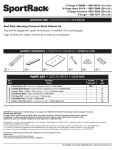
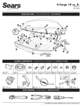
LD14x • User manual • LD140-M7 + SM25 LD141-M7-R-… LD142-M7-R-… Avoid running the sensor cable near high voltage power cables (e.g. drive cables). Avoid mounting sensor head near capacitive or inductive noise sources such as relays, motors, and switching power supplies. Connect according to chapter 5. 2 - Identification Description The display and sensor can be identified by the label's data (ordering code, serial number). This information is listed in the delivery document. For technical features please refer to the product catalogue. This manual describes the LD14x battery display series and the sensors of the SM25 series. The purpose of this system is to display linear or angular displacements on industrial machines and on automation systems. The measurement system includes a battery powered LCD display, magnetic tape and a magnetic sensor. As the sensor is moved along the magnetic tape, it detects the displacement which is shown on the display. The flexibility of the tape allows it to be used for both linear and angular applications. 3 - Installation Install the product according to the protection level provided. Protect the system against knocks, friction, solvents, temperatures under –0°C (32°F) and over +60°C (+140°F). Be sure that the system is mounted where hard or sharp objects (e.g. metal chips) do not come into contact with the magnetic scale and the bottom of the sensor head. If these conditions cannot be avoided provide a wiper or pressurized air. 4 - Mounting recommendations 4.1 Display Push the display into the cut-out without panel clips. Install panel clips on the display's housing and screw until fixed and stable. Power supply by 1.5V commercial battery type C (or AM2 / BABY / LR14 / MN1400 / SP/HP11). Chapters 1 2 3 4 5 6 7 8 Safety summary Identification Installation Mounting recommendations Electrical connections Setup RS232 serial interface (only with option I1) Dimensional drawings and cut-out 4.2 Magnetic tape See manual supplied with the magnetic tape. 4.3 Sensor mounting 4.3.1 Sensor SM25-R (rectangular) Sensor can be fixed by means of two M3 screws over the buttonholes. Make sure that the gap between sensor and tape is in respect with (fig. 1) along the total measuring length. Avoid contact between the parts. You can check planarity and parallelism between sensor and magnetic tape using a feeler gauge. 1 - Safety summary We strongly recommend carefully reading this user manual and following the installation guidelines: • Sensor head should be installed as close as possible to the display. ____________________________________________________________________________________________ MAN LD14x I_E_D 4.3 9 www.lika.it www.lika.biz LD14x 5 - Electrical connections D 5.1 SM25 sensor (only LD140) Plug in the sensor's Mini-DIN connector (circular) on backside of the display. <3° <1° 5.2 RS232 serial interface (only with option I1) Connect PC to LD14x with NULL MODEM COMPUTER AT CROSS OVER cable (9 pin female - 9 pin female) available in commerce. Electrical cable connection: Pin PC Function Pin LD14x 1 2 Rx 3 3 Tx 2 4 DTR 6* 5 GND 5 6 DSR 7 RTS 8* 8 CTS 9 * Power supply has to be provided to RS232 interface to avoid battery consummation. If not connect to the PC provide power supply (8-15Vdc) to pin 6 or 8. External supply isn’t needed if using a Modem computer cable! <3° figure 1 D = 0,1 mm - 1,0 mm 4.3.2 Sensor SM25-C (circular) The sensor can be fixed in a corresponding mounting hole by means of the two nuts. Make sure that the gap between sensor and tape is in respect with (fig. 2) along the total measuring length. Observe the correct alignment of the marker on the tape. Avoid contact between the parts. You can check planarity and parallelism between sensor and magnetic tape using a feeler gauge. D Marker <3° figure 2 D = 0,1 mm - 1,0 mm ____________________________________________________________________________________________ MAN LD14x I_E_D 4.3 10 www.lika.it www.lika.biz LD14x 6 - Setup 6.2.4.1 Fractional offset display The fractional inch display mode allows to set offset values (OFS) in the following way: - 1st digit blinking → increases 1/64” pushing key. - 2nd digit blinking → increases 1/32” pushing key. - 3rd digit blinking → increases 1/16” pushing key. - 4th digit blinking → increases 1/8” pushing key. - 5th digit blinking → increases 1” pushing key. - 6th digit blinking → increases 10” pushing key. 6.1 Key's function : UP (select value) : Shift links (select digit) * : Save (save data) P : Program (programming/change parameter) 6.2 Key combinations / Quick functions 6.2.1 Set datum (reference) Push * key for 3 sec. to access reset function (“rESEt” will be displayed). Push P key to exit function (no reset). Push * key twice to confirm datum value (“donE” will be displayed). Display value = rEF + OFS1 + OFSx (where OFSx is the actually set Offset value). This function is enabled only if “F_rSt” parameter is set “yES”. 6.2.5 Datum modification Push simultaneously P and keys to display datum value rEF. Use and keys to change value and save with * key. This function is enabled only if “F_rEF” parameter is set “yES”. 6.3 Setup / Parameter setting Push P key for 3 s to enter setup and “SEtUP” is displayed. Push key to enter MENU 1 (parameters) Push * key to enter MENU 2 (RS232 serial interface) Push P key to access the next Parameter and Parameter setting. Push P key for 3 s to exit the setup at any point. 6.2.2 Incremental measurement Push P and * key simultaneously to switch from absolute measurement to incremental. Zero setting in incremental modes (see 6.2.1) does not change absolute value in the background. The function is enabled only if "F_rEL" parameter is set "yES". 6.3.1 Default parameters (factory settings) All default values are written in BOLD characters. The display can be reset to default parameters with the following procedure: • take out battery and wait for 10 s. • while putting in the battery push * key (“dEFPar” is displayed) --------------------------------------------------- 6.2.3 Mm/inch display modes Mm/inch display modus can be changed by pushing key for 3 s. The function is enabled only if "F_mmI" parameter is set "yES". 6.2.4 Offset value modification Push P and keys simultaneously to display 1. Offset value (OFS1). Use and keys to change value and save with * key. Further Offset values OFS2 and OFS3 can be changed only in setup menu. Offset function is enable if “F_oFS” parameter is set “yES”. key allows to scroll OFS1, OFS2 and OFS3 values. OFS1 = actual value + OFS1 + rEF OFS2 = actual value + OFS1 + OFS2 + rEF OFS3 = actual value + OFS1 + OFS3 + rEF 6.3.2 Parameter list MENUE 1 Unit Measurement unit [dEC, FrEE, dG1, dG2, IdEC, Ifrct] Sets the measurement unit and the display mode. dEC = linear measurement display (decimal) FrEE = display with conversion factor dG1 = angular display (-∞..-0,1°..0,0°..+0,1°..+∞) dG2 = angular display (..359,9°..0,0°..359,9°..0,0°..) IdEC = inch display mode Ifrct = fractional inch mode (eg. 12.31.64 = 12" 31/64) * = save, P = next parameter, P for 3 s. = exit ____________________________________________________________________________________________ MAN LD14x I_E_D 4.3 11 www.lika.it www.lika.biz LD14x COn only with Unit = FrEE, dG1, dG2 Allows to set a free conversion factor to display non-metric units or angles. Valeu range: FrEE = 0,00001 - 1,00000 dG1, dG2 = 0,00001 - 9,99999 6.3.3 Additional function of MENUE 1 F_mmI mm/inch function [yES, no] Enables the mm/inch function (by pushing key) yES = enabled no = disabled * = save, P = next parameter, P for 3 s. = exit Example 1: Want to display a 90° angle (from 0° to 90°) with 0,1° resolution on a round table with 785,4 mm circumference. The measurement length on 360° is 785,4 mm, though on 90.0° it is 785,4 / 4 = 196.35. COn = 900 : 19635 = 0,045836 F_rEL Incremental measurement function [yES, no] Enables incremental measurement function (by pushing P and * keys). yES = enabled no = disabled * = save, P = next parameter, P for 3 s. = exit F_rSt Datum function [yES, no] Enables datum function (by pushing * key). yES = enabled no = disabled * = save, P = next parameter, P for 3 s. = exit Example 2: Want to display angles on a magnetic ring with diameter 114,5 mm. The circumference is 114.5 * 3.14 = 359.53 mm COn = 3600 : 35953 = 0,10013 * = save, P = next parameter, P for 3 s. = exit F_rEF Datum modification function [yES, no] Enables reference modification function (by pushing P and key). yES = enabled no = disabled * = save, P = next parameter, P for 3 s. = exit rES Resolution (only with Unit = dEC, FrEE, dG1, dG2, IdEC ) Sets the resolution to be displayed. Unit = dEC, FrEE, dG1, dG2 = 0.001, 0.005, 0.01, 0.05, 0.1, 0.5, 1 Unit = IdEC = 0.0001, 0.0005, 0.001, 0.005, 0.01, 0.05, 0.1 * = save, P = next parameter, P for 3 s. = exit F_oFS Offset modification function [yES, no] Enables offset modification function (by pushing P and keys). yES = enabled no = disabled * = save, P = next parameter, P for 3 s. = exit dIr Counting direction [uP, dn] uP = up (standard direction) dn = down (inverted direction) * = save, P = next parameter, P for 3 s. = exit --------------------------------------------------- rEF Datum value [-999999, 999999] Absolute reference value for the measuring system. This value is displayed by pushing * key for 3 s. (displayed value includes previously set offset values). * = save, P = next parameter, P for 3 s. = exit OFS1 Offset1 value [-999999, 999999] First offset value (e.g. tool correction). This value is added to actual value (see 6.2.3.) * = save, P = next parameter, P for 3 s. = exit ____________________________________________________________________________________________ MAN LD14x I_E_D 4.3 12 www.lika.it www.lika.biz LD14x 7 - RS232 serial interface (option I1) OFS2 Offset2 value [-999999, 999999] Second Offset value. This value is added to actual value and OFS1. * = save, P = next parameter, P for 3 s. = exit If the display is provided with RS232 serial interface, the following commands can be used. 7.1 RS232 parameters OFS3 Offset3 value [-999999, 999999] Third Offset value. This value is added to actual value, OFS1 and OFS2. * = save, P = next parameter, P for 3 s. = exit 9600 Baud, 8Bit, no Parity, 1 Stop bit, Xon/Xoff 7.2 Serial commands Serial commands must have the following structure: |ADCMND=X where: |: PC keyboard symbol AD: device address (00 to 31) 2 digit CMND: command (see command list) X: value range (see command list) When the setup is completed the display shows "rESEt" Push * key twice to reset the display and quit the setup. "donE" will be displayed. Push P key quit the setup without resetting the display. "no rSt" will be displayed. --------------------------------------------- Upon receipt of a wrong command the display will answer with the same command + ? and checksum (e.g. sent command: |02azs → answer |02azs?EF) Any common terminal program can be used for communication with LD140 (e.g. Hyperterminal). Commands will be send after confirmation by ENTER key (carriage return). 6.3.4 Parameter list MENUE 2 Ad xx Device address [01, 31] Setting of device address (only if ordered with serial interface (option I1). For setting use and keys. * = save, P = next parameter Answers are structured as follows: H_cntr Hour meter (1/10 h) Elapsed time indication (display connected to battery). Resolution is 1/10 hour (6 minutes). * = save, P = next parameter ADCMND:SXXXXXXXXCK where: AD: device address CMND: command XXXXXXXX: value CHKS: checksum The checksum is equal to the least significant byte of the summing the hex values of all characters transmitted. Example: The displayed position is 8,29. The position of device with address 01 is read by means of the |01TPOS command. The answer is: 01TPOS:+000008299F The sum of hex values of all characters is the following: 30+31+54+50+4F+53+3A+2B+30+30+30+30+30+ 38+32+39 = 39F The least significant byte of 39F is 9F which is the checksum. ____________________________________________________________________________________________ MAN LD14x I_E_D 4.3 13 www.lika.it www.lika.biz LD14x 7.2.1 Command list (below the device address is indicated with AD) Measurement unit [0, 5] |ADRUNI=X Sets the measurement unit and display mode. X=0→ dEC = decimal mode X=1→ FrEE = display with conversion factor X=2→ dG1 = angular (-∞..-0,1°..0,0°..+0,1°..+∞) X=3→ dG2 = angular (..359,9°..0,0°..359,9°..0,0°..) X=4→ IdEc = decimal inch display mode X=5→ Ifrct = fractional (es. 12.31.64 = 12" 31/64) Answer: ADTUNI:+0000000XCHKS Zeroing of device address |00RSET Address of all connected devices is set to zero (0). Device address [1, 31] |00INIT=X Sets address of all connected devices to value X. Display device address |00DADR Displays device address until P key is pushed. Read measurement unit |ADTUNI Reads the status of measurement unit. Answer: ADTUNI:+0000000XCHKS Change device address [1, 31] |ADRADR=X Changes actual device address AD to X. Answer : ADTADR:+XCHKS (CHKS is checksum and X is value). Resolution [1, 5, 10, 50, 100, 500, 1000] |ADRRES=X Sets linear resolution in mm or inch. X=1→ 0.001/0.0001, X=5→ 0.005/0.0005, X=10→ 0.01/0.001, X=50→ 0.05/0.005, X=100→ 0.1/0.01, X=500→ 0.5/0.05, X=1000→ 1/0.1 Answer: ADTRES:+XCHKS Read actual position |ADTPOS Reads actual position of device AD (resolution of value is 0,01mm or 0,001 inch depending on settings). Read resolution |ADTRES Reads value of actual resolution (see values above). Answer: ADTRES:+XCHKS Change counting direction [0, 1] |ADRDIR=X Sets counting direction. X=0 → uP = standard direction X=1→ dn = inverted direction Answer: ADTDIR:+0000000XCHKS Free conversion factor COn [with FrEE 0,00001 - 1,00000 / with dG1, dG2 0,00001 - 9,99999] |ADRFRE=X Sets free conversion factor COn (see chapter 6.3.1). Answer: ADTFCO:+XCHKS Read counting direction |ADTDIR Reads the actual counting direction. X=0→uP , X=1→dn Answer: ADTDIR:+0000000XCHKS Read COn conversion factor |ADTFCO Reads value of actual COn factor. Answer: ADTFCO:+00X.XXXXCHKS Display mm/inch display mode [0, 1] |ADRMMI=X Changes display mode from mm to inch. X=0→ mm, X=1→inch Answer: ADTMMI:+0000000XCHKS ____________________________________________________________________________________________ MAN LD14x I_E_D 4.3 14 www.lika.it www.lika.biz LD14x Read mm/inch display mode |ADTMMI Reads status of mm/inch display mode. X=0→ mm, X=1→ inch Answer: ADTMMI:+0000000XCHKS Datum value modification [0, 1] |ADRRFE=X Enables Datum value modification combination P and ). X=0→ oFF, X=1→ on Answer: ADTRFE:+0000000XCHKS Incremental measurement function [0, 1] |ADRRLA=X Enables incremental measurement function (key combination P and *). X=0→ oFF , X=1→ on Answer: ADTRAE:+0000000XCHKS (by key Read Datum value modification |ADTRFE Reads status of Datum value modification. X=0→ oFF, X=1→ on Answer: ADTRFE:+0000000XCHKS Offset function [0, 1] |ADROFE=X Enables Offset function (by key combination P and ) X=0→ oFF, X=1→ on Answer: ADTOFE:+0000000XCHKS Read incremental measurement |ADTRAE Reads status of incremental measurement function. X=0→ oFF, X=1→ on Answer: ADTRAE:+0000000XCHKS Incremental measurement [0, 1] |ADRRLA=X Sets from absolute display mode to incremental (relative). X=0→ oFF, X=1→ on Answer: ADTRAE:+0000000XCHKS Read Offset function |ADTOFE Reads status of Offset function. X=0→ oFF, X=1→ on Answer: ADTOFE:+0000000XCHKS Read incremental measurement |ADTRLA Reads status of absolute/incremental display mode. X=0→ oFF, X=1→ on Answer: ADTRLA:+0000000XCHKS Datum value [-999999, 999999] |ADRREF=X Absolute Reference value for the measurement system. (the value has resolution 0,01mm or 0,001 inch depending on the display settings). Answer: ADRREF:XCHKS Datum function [0, 1] |ADRRSE=X Enables Datum function (by pushing * key). X=0→ oFF, X=1→ on Answer: ADTRSE:+0000000XCHKS Read Datum value |ADTREF Reads actual Datum value. Answer: ADTREF:XCHKS Read Datum function |ADTRSE Reads status of Datum function. X=0→ oFF, X=1→ on Answer: ADTRSE:+0000000XCHKS Offset1 value [-999999, 999999] |ADROF1=X Sets Offset1 (OFS1) value (the value has resolution 0,01). Answer: ADROF1:XCHKS Read Offset1 value |ADTOF1 Reads actual Offset1 value. Answer: ADTOF1:XCHKS ____________________________________________________________________________________________ MAN LD14x I_E_D 4.3 15 www.lika.it www.lika.biz LD14x Offset2 value [-999999, 999999] |ADROF2=X Sets Offset2 (OFS2) value (the value has resolution 0,01). Answer: ADROF2:XCHKS Rev. 0 3 4 Man.Vers. 1.0 4.1 4.2 4.3 Description 1^ issue SW + Manual update Chap.5 correction Reset function correction (chap. 6.2.1) Read Offset2 value |ADTOF2 Reads actual Offset2 value. Answer: ADTOF2:XCHKS Offset3 value [-999999, 999999] |ADROF3=X Sets Offset3 (OFS3) value (the value has resolution 0,01). Answer: ADROF3:XCHKS Read Offset3 value |ADTOF3 Reads actual Offset3 value. Answer: ADTOF3:XCHKS 8 - Cut-out 8.1 LD140 and LD142 Provide a 94 x 68 mm (w x h) cut-out. 8.2 LD141 Check details on product catalogue. LIKA Electronic Via S. Lorenzo, 25 - 36010 Carrè (VI) - Italy Tel. +39 0445 382814 Fax +39 0445 382797 Italy: eMail [email protected] - www.lika.it World: eMail [email protected] - www.lika.biz ____________________________________________________________________________________________ MAN LD14x I_E_D 4.3 16 www.lika.it www.lika.biz