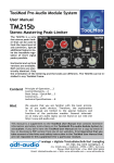
1
® adt-audio ® ToolMod Pro-Audio Module System User Manual analoge + digitale Tonstudiotechnik Karl Juengling Inh. Dipl.-Ing. Gerd Juengling e. K. 4-6, Scholtwiese • Gladbeck • 45966 • NRW • Germany Phone: 0049 2043 51061 • Fax: 0049 2043 56844 Email: [email protected] Web: www.adt-audio.com + www.pro-audio-store.de V1.2/2014 - English adt-audio ® ® ToolMod Pro-Audio Module System Content Standard Power Cables and custom Cables....13 Important Hint: maximum Current....14 Grounding and Protective Ground....14 Important Hint: do not power on before....14 Placement/Installation of the Power Supply Units....15 Overloading Power Supply Units....15 Overload Effects of Power Supply Units....15 Very high Temperature of the Heat Sink....16 Hum....16 ToolMod Modules....17 Installing and removing Modules....17 Module Versions....17 Difference between 1U-high and 2U/4U-high Frames....17 Fixing of Modules in the Frame....18 Modules in the 1U-high Frame....19 Modules in the 2U-high-Frame....20 Module in the 4U-high and 6U-high Frame....20 Audio Inputs and Outputs....21 Input and Output Connector Pin Assignments....23 Screening....23 1U-high Frame with build-in Power Supply....24 Audio Installation....25 Ground....25 Unbalanced Inputs and Outputs....26 Unbalanced Output -> balanced ToolMod Input....26 Balanced ToolMod Output -> unbalanced Input....26 Notes....27 General Information.....3 Copyright....3 Trade Marks....3 CE-Declaration of Conformity....3 Encironmental Protection....3 Important Safety Instructions....4 Water and Humidity....4 Insertion of Objects or Fluids....4 Power Supply Units....5 Protective Ground....5 Ligthning....5 Ventilation....6 Alterations....6 Module Frames....6 Installing and removing Modules....6 Repairs....7 Spare Parts....8 Safety Test....8 Factory Repair....8 Cleaning....8 Power Supply....9 Mains Voltages and Frequencies....9 Output Voltages....9 Power Cables....9 Power Supply Rating....10 Precise Calculation of the Current Consumption....10 Rule of Thumb....10 Power Supply Units....11 ToolPwr-M....11 ToolPwr-S....11 ToolPwr-E....11 Phantom Power....12 Power Supply Outputs....12 Power Supply Connections between Power Supply Unit and Frame....12 Power Supply Connections between Frames....12 Power Supply Pin Assignment....13 2 ® ToolMod Pro-Audio Module System General Information adt-audio ® Preface and Disclaimer This manual contains general information on the adt-audio® module system ToolMod®. By no means does this information represent guaranteed particular characteristics or results of use. The information in this manual has been carefully compiled and verified. Due to our policy of continuous product improvement, we reserve the right to make product changes without prior notice. All specifications are subject to change without notice. Copyright This manual is copyright protected. Do not copy, distribute, or translate into other languages without permission in writing from adt-audio® Karl Juengling. All rights reserved. Trade Marks adt-audio® and ToolMod® are registered trademarks of analoge + digitale Tonstudiotechnik Karl Juengling. All other trademarks are the property of their respective owners. CE Declaration of Conformity Manufacturer: Fa. Karl Juengling Type of Equipment: Audio Signal Processor Product: ToolMod Pro-Audio Module System, consisting of: Modules, Mounting Frames, Power Supply Units and Accessories Compliance Engineer: Gerd Juengling Test Basis: EN50081-1:1992, EN50082-1:1992, EN61000-3-3:1995, EN60065:1993 Class1, EN61000-3-2:2000, EN60065:2002, EN55013:2001, EN55020:2002, 73/23 EWG; 93/68 EWG We hereby declare that the construction of the ToolMod system complies with the standards and regulations listed above. Environmental Protection This product can be recycled. Products bearing this symbol must not be thrown away with normal household waste. At the end of the product‘s 3 adt-audio ® ToolMod Pro-Audio Module System ® Safety Instructions life, take it to a collection point designated for recycling of electrical and electronical devices. Find out more about return and collection points through your local authorities. The European Waste Electrical and Electronic Equipment (WEEE) Directive was implemented to dramatically reduce the amount of waste going to landfills, thereby reducing the environmental impact on the planet and on human health. Please act responsibly by recycling used products. If this product is still useable, consider giving it away or selling it. WEEE-Registration: DE 59049716 Important Safety Instructions Please note and retain this information! Read and follow all safety and operation instructions carefully before you start using the product! Heed all warnings! This manual provides general information on the ToolMod system, the frames and the power supply units, and the installation and exchange of modules. Please keep this manual; since the module manual do not contain the information in this manual, you will need it any time you change your system. Extensive information on the entire ToolMod system and manuals for download can be found on our website www.adt-audio.com. Water and Humidity Do not use the devices near water, near a bathtub, in a wet basement, near a swimming pool, and the like. Do not expose the devices to rain or moisture. WARNING: RISK OF DEATH BY ELECTRIC SHOCK! Insertion of Objects or Fluids NEVER allow any kind of object to get into the devices thru ventilation slots or other openings in the housing. You can easily come into contact with dangerous electric voltage or cause damaging short circuits. NEVER allow any kind of fluids to be spilled or sprayed on the devices. Such actions can cause damage, 4 ® ToolMod Pro-Audio Module System Safety Instructions adt-audio ® dangerous electric shocks, or fire. WARNING: RISK OF DEATH BY ELECTRIC SHOCK! In case an object or fluids got into a device, disconnect the power immediately and contact a qualified service technician! Power Supply Units Do not defeat the safety purpose of the grounding type Euro outlet. Use only power cables and wall outlets that provide protective ground connection to the power supply units. Grounding type cables and outlets have two contacts for the ac line and a third grounding contact. The third, grounding contact is provided for your safety. If the provided cable does not fit into your wall socket, consult an electrician for replacement. Protect the power cord from being walked on or pinched particularly at plugs, convenience receptacles, and the point where they exit from the power supply unit. Unplug the power supply units before lightning storms or when unused or unattended for long periods. This will prevent damage to the power supply units from lightning and power line surges. WARNING: DO NOT TOUCH OR DISCONNECT DEVICES DURING A LIGHTNING STORM RISK OF DEATH BY ELECTRIC SHOCK! Make sure that the voltage selector of the power supply is set to the correct voltage BEFORE YOU CONNECT THE POWER SUPPLY. The power supply units must be located such that the rear AC socket and connected power cord are readily accessible. Avoid any kind of overload in connections to wall sockets, extension or splitter power cords. Overloads create serious risk of FIRE HAZARDS and DEATH BY ELECTRIC SHOCK! WARNING: RISK OF DEATH BY ELECTRIC SHOCK! NEVER OPEN THE HOUSING OF A POWER SUPPLY UNIT BEFORE YOU DISCONNECT THE POWER CORD. Even if the unit is switched off, dangerous voltage is present inside the unit! In order to avoid exposure to any residual voltage, the units should be disconnected from any power source at least 5 minutes before opening! 5 adt-audio ® ToolMod Pro-Audio Module System ® Safety Instructions Do not use different fuses for replacement. NEVER replace a fuse with another one with higher current values or different tripping behavior. Use only fuses with the original values. Other fuses can cause damage, fire, and/or electric shocks. WARNING: RISK OF DEATH BY ELECTRIC SHOCK! Ventilation slots and/or openings prevent the devices from overheating. Do not block or cover ventilation openings. Never place the units on a soft surface (carpet, sofa, pillow, etc.). Make sure to provide enough space (4 to 5 cm / 2 inches) around the devices, when mounting into a rack or cabinet. Do not attempt any alterations to the units without express written approval from adt-audio Karl Juengling! Unauthorized alterations void any warranty and liability! Module Frames It is not necessary to remove cover sheets when installing or removing modules. Modules can be removed and exchanged after unbolting the knurled screws that fix the modules in the frame. Additional modules can be installed after removing blind panels, where necessary. Do not remove cover sheets of the frames and do not make any changes. The supply voltages of +/- 25 volts and 48 volts DC are accessible inside the frames. Although these voltages are low, there is still the risk of electric shocks. Important Note: In no event, open the housing of the power supply units before the power cord is disconnected. Wait at least 5 minutes after disconnecting the cord to avoid exposure to residual voltage. Otherwise, no liability will be assumed. Installing and removing Modules Before you begin, disconnect the devices from the power line, and wait 5 minutes until any residual voltage has discharged. Before you reconnect the power and switch on, make sure that all modules fit into the mating plugs in the frame and that all modules are fixed. Do not install any modules with visible damages. 6 ® ToolMod Pro-Audio Module System Safety Instructions adt-audio ® Modules can have sharp corners and edges, sharp tips of screws, pointed wire ends and other dangerous parts. There is the risk of injury. Be careful, make sure that you do not hurt yourself, and take care where to touch the modules. Never use control knobs as handle to remove the modules from the frame. The fixing screws are knurled neck collar screws. After unbolting the modules from the frame, the screws fit into taps in the faceplates and can be used as handles for removing. Pull out the modules always using the neck collar screws. Otherwise, there is the risk of damage for pots and other control elements. Like computer add-on boards, the PCB’s of the modules do not have cover sheets. Make sure that you act with appropriate caution and do not touch any components. Qualified personnel should perform installing and removing. With respect to possible physical damage or injuries, any manipulation is at your own risk and we are not liable for any physical damage or injury. Repairs In case that: • you think that repairs are necessary • objects or fluids have gotten into a device • the device fell to the ground • the device is otherwise mechanically damaged • the device is not working properly • the power cord is damaged • the device was exposed to rain • the device fell into water Disconnect the power immediately and contact a qualified service technician. Make sure to inform the service technician about anything that has happened to the device. In case that the power cord is damaged, do not touch the cord or the device but switch of the main circuit breaker before disconnecting the power cord. 7 adt-audio ® ToolMod Pro-Audio Module System ® Safety Instructions WARNING: RISK OF DEATH BY ELECTRIC SHOCK! Spare Parts Make sure that only original parts are used for repair or replacement. Wrong spare parts may cause fire, electric shocks, subsequent damages, and other dangerous risks. Otherwise, the warranty is void and no liability will be assumed. Safety Test Insist that the service technician conducts a thorough safety test to ensure that the condition of the repaired device is safe and up to factory standards. Factory Repair If you intend to send defective devices to the factory, please get in touch with us by phone (0049 2043 51061) or by email (support (at) adt-audio.com) and let us know: • Type and serial number of the defective device • Date of purchase and name of the dealer, if you have not purchased directly from the factory • a brief description of the problem and of the history (fluids in the device, something that happened, etc.) We will tell you how to proceed. Cleaning Before you begin to clean devices, disconnect the power cord. Clean only with a dry cloth and do not use any solvents or sprays! For removing stubborn contaminations, you may use a cloth soaked with isopropyl alcohol as cleaning agent. Isopropyl alcohol does not attack the powder coating and the plastic parts. Make sure that the alcohol is entirely evaporated before you reconnect the unit to the power line. Otherwise, you risk fire and electrical shocks! 8 ® ToolMod Pro-Audio Module System Power Supply adt-audio ® Power Supply A range of linear power supply units is available for the ToolMod module system. Mains Voltages and Frequencies All power supply units are suited for 230 and 115 volts ac power lines with 50 or 60 Hz. Output Voltages All supply units provide +/- 25 volts for the audio amplifiers of the ToolMod modules and an additional 48 volts phantom power for condenser microphones. Power Cables 6 core, high cross section control cables with 5-pin XLR connectors are used for the connection between the power supply units and the frames and between frames. The pin assignment of the 5-pin XLR connectors is compatible with the ToolMix series of summing boxes, the ToolKit channel strip and the ToolMod Faderbox. The power supply units can be used with any combination of these devices without any disadvantage, if the capacity of the particular power supply unit is sufficient. TM400 Series ToolMod Consoles come with a 5-pin XLR power output connector for ToolMod, ToolMix, and ToolKit units. Using the power supply unit of a 9 adt-audio ® ToolMod Pro-Audio Module System ® Power Supply ToolMod console with sufficient capacity for these units is also possible. Power Supply Rating Type and number of modules and units determine the version of the required power supply unit. The three standard power supply units for the adt-audio Tool devices can be used with almost all existing system setups. Which power supply unit is suited for a particular setup is determined by the current consumption of the modules and units and, on rare occasions, by the operation level and the load on the outputs. The current consumption of the modules and other Tool devices is listed in the technical specs of the particular device in the manuals on the web pages (www.adt-audio.com). The operation level and the load is only important if the load on a considerable number of outputs is a lot lower than 2 kΩ while the operation level is close to the headroom of + 30 dBu. Precise Calculation of the Current Consumption To determine the exact current consumption of a ToolMod system, the current consumptions of all modules that can be found in the specifications and on the module web pages are simply added. The nominal current consumption that is listed in the specification refers to usual operating conditions; meaning usual operation level and usual load of the outputs, and includes a safety margin. If many outputs are loaded with the minimum load resistance of 1200 Ω or with lower values AND if these outputs operate at levels close the headroom of + 30 dBu, the output power is in the range of 0.5 watts and an additional supply current of 30 mA per such output is required. Since the output power is proportional to second power of the output voltage with a given load resistor, either lower level or higher load resistance reduces the output power and therefore the current consumption considerably. There are rare cases where this combination of level and resistance exists. Rule of Thumb Since the current consumption of most of the modules is in the same range, a rule of thumb can be applied to roughly determine if capacity of a particular power supply is sufficient for a ToolMod system or not. Number of mono modules * 0.1 amps + number of stereo modules * 0.2 amps With a ToolMod set with 5 mono modules the result is 5 * 0.1 amps = 0.5 amp. Using 5 stereo modules instead results in 5 * 0.2 amps = 1 amp. Since there are a few modules with a higher current consumption you ought to check the specifications in any case. 10 ® ToolMod Pro-Audio Module System Power Supply adt-audio Power Supply Units There are three standard power supply units with different capacities: ToolPwr-M, ToolPwr-S and ToolPwr-E ToolPwr-M ToolPwr-S The ToolPwr-M is a desktop unit with a nominal output current of 1 amps and a peak output current of 1.5 amps. The ToolPwr-M comes with 1 single 5-pin XLR output connector. The nominal power is 100 watts. The ToolPwr-S is a 2U-high 19“ unit with a nominal output current of 2.5 amps and a peak output current of 4 amps. The ToolPwr-S comes with two 5-pin XLR output connectors. The nominal power is 230 watts. ToolPwr-E Like the ToolPwr-S, the ToolPwr-E is a 2U-high 19“ unit; however, the nominal output current is 5 amps and the peak output current is 7 amps. The ToolPwr-E comes with a bigger power transformer, a larger heat sink and high power voltage regulators and bigger load capacitors. Like the ToolPwr-S it has two 5-pin XLR output connectors. The nominal power is 450 watts. 11 ® adt-audio ® ToolMod Pro-Audio Module System ® Power Supply Phantom Power The considerations of the output current refer to the capacity of the audio supply voltages. The 48 volts phantom supply in each of the power supply units is designed to supply high current condenser microphones if the entire capacity of the audio supply is used for microphone amplifiers. Therefore, there is no need to consider the capacity of the phantom power supply. Power Supply Outputs Depending on the power supply unit, there are one or two 5-pin XLR output connectors. The picture shows the rear panel of a ToolPwr-S with 2 output connectors, wired in parallel. Power Supply Connections between Power Supply Unit and Frame 6 core, high cross section control cables, fitted with 5-pin XLR plugs are used for the power cables. The cross section of each core is 0.75 mm2 = AWG18. The 5-pin XLR connectors and the voltage drop along the cable determine the maximum current of 3 amps. Power supply Connections between Frames All ToolMod frames come with a 5-pin male XLR and a parallel 5-pin female XLR. Several frames can be connected in daisy-chain mode, as long the total current is lower than 3 amps per cable. All power cables are extension cords with a female and a male plug. The pictures show the rear panel of a 1U high ToolMod frame and a 1 ft. and 10 ft. cable. 12 ® ToolMod Pro-Audio Module System Power Supply adt-audio Power Supply Pin Assignment ® The pin assignment of the power supply unit and the ToolMod frame matches the pin assignment of all other adt-audio Tool devices. Any combination of these devices can be connected to any power supply and any other Tool unit, as long as the capacity of the power supply unit is sufficient. Standard Power Cables and custom Cables The following standard power cables are available from stock: 10 ft./3m, 5 ft./1.5 m, 3 ft./1 m, 2 ft./60 cm, and 1 ft./30 cm. Custom cables up to 6 meters are available at short notice. The 10 ft./3 m versions are usually used for connecting the power supply unit to the first frame. The shorter cables are used to connect several frames in daisy chain mode. 13 adt-audio ® ToolMod Pro-Audio Module System ® Power Supply IMPORTANT HINT: The maximum current per cable must not exceed 3 amps. The XLR connectors are not designed for higher currents than 3 amps. In addition to a higher failure probability of the connectors, higher current results in higher voltage drop along the cable and therefore a lower supply voltage of the modules. This may result in a reduction of the headroom and degraded transient performance. To make sure that the maximum current will not exceed 3 amps with a reasonable safety margin, connect not more than a single 4U high frame, two 2U high frames, or four 1U-high frames to a single power supply output. Of course this is only a rule of thumb. The exact current consumption results from the addition of the current consumption of the modules, the load resistance, and the operation level, as explained in detail above. Grounding and Protective Ground As factory standard, the protective ground from the Euro inlet of the power supply unit is connected via the power supply cable to the chassis of the frame, the audio ground, and the screen pins of all connectors. This principle ensures that all accessible parts are connected to the protective ground. However, the connections between the different grounds are not part of the basic design of the ToolMod series. The three ground circuits, protective ground = chassis, audio ground = 0 volts of the power supply, and screen-ground = all screening pins of the audio connectors, are fully isolated from each other and connected only at one point inside each frame. If ground loops show up due to the connection of the protective ground to the audio ground and/or screen ground, it is possible to isolate the ground circuits. For safety reasons, it is not possible to isolate the protective ground from the chassis. In any case it is necessary to make sure that the safety of the system is ensured if ground connections are removed. Contact us before you change anything! IMPORTANT HINT: Do not power on the system before the power cables are installed! If you unplug or plug in a power cable while the system is under power by accident, there is no risk that a module or the power supply unit become defective. If the load on the power supply unit is low, the system will keep working. However, if the load of the power supply unit is high, the inrush current when you plug in a power cable is very high, since the oversized capacitors in all modules have to be loaded. In this case it might happen that one of the protec14 ® ToolMod Pro-Audio Module System Power Supply adt-audio ® tion circuits in the power supply unit is triggered and shuts down one or both audio supply voltages. This results in very high background noise and a reduced intensity of the control LED of the particular supply voltage on the faceplate of the power supply unit. If this happens, switch off, wait about 1 minute, and switch on again. Placement/Installation of the Power Supply Units. Do not place or install the power supply unit directly below, above, or next to a ToolMod frame. The most important reason for external power supply units is the electro magnetic field of the toroidal power transformer that can only be effectively screened using MU-metal at very high cost. Even though the magnetic field of a high quality toroidal transformer is a lot lower than the field of a cheap standard transformer, it is still existing and may induce hum into sensitive devices, especially those with input and output transformers and/or inductors that are not sufficiently screened and with high gain and high input impedance. Since the intensity of an electro magnetic field is reciprocally proportional to the second power of the distance, any disturbance caused by magnetic fields is reduced to a quarter is the distance is doubled. If you install a power supply next to an audio device with sensitive circuitry, you reduce the advantage of the external power unit significantly. With a proper placement of the power supply unit, about 1 m away from any audio gear, you can install any module in any module compartment without hum or other disturbances from electro magnetic fields. If you have to deal with such problems and no improvement can be achieved when moving the power supply unit away, please check for other devices that produce magnetic fields. In addition to power amplifiers and big power supply units, very often small plug power supplies with under designed transformers are the reason for such a problem. Check for these devices and try to move them away. If the reason for the hum is an electro magnetic field, you will notice a difference as soon as you start changing the position. Overloading Power Supply Units When you upgrade your system with more modules and/or additional frames it might happen that the capacity of the power supply unit is not sufficient anymore. We strongly advice that you consider the capacity of your power supply if you add more modules. If you not sure if your supply unit is sufficient for the new setup, just ask for advice. Overload Effects of Power Supply Units You will notice if a power supply units is overloaded if one of the following effects occur: 15 adt-audio ® ToolMod Pro-Audio Module System ® Power Supply Very high Temperature of the Heat Sink and the Housing With increasing output current, the amount of heat that has to be dissipated over the heat sink increases significantly. The total power loss is not only determined by the output current but also by the local mains voltage. High mains voltage causes higher heat dissipation; low mains voltage reduces the heat dissipation but may result in a reduced capacity of the power supply unit. Since all ToolMod power supply units work without internal fans, the temperature of the heat sink at a certain combination of output current and mains voltage depends also on the installation of the unit. If you notice that the temperature of the heat sink is very high, please check if the airflow along the heat sink is sufficient. Fresh air should pass along the heat sink from the bottom and there must be a free pass for heated air to the top. If the installation or the placement of the power supply unit does not impede the airflow, the prove for an overload is that the overheat protection circuitry shuts down the output voltages after a certain time. If this happens, there is a very high background noise, almost no headroom, and the intensity of the control LEDs on the faceplate of the power supply unit is a lot lower than normal. If this happens, switch off, wait some time to allow the unit to cool down, and switch on again. Please take into account that the supply unit will shut down again when the temperature raises above the threshold of the protection circuitry. In the long run you will need to get another power supply unit with higher capacity or a second unit, if you have more than 1 frame an are able to use several power supply units for the different frames. To keep working until the problem is solved, you can remove the power supply from the rack and place a fan directly next to the heat sink. This will improve the heat flow and the time before the temperature control shuts down again will be considerably longer. Hum With a standard to high mains voltage, the heat dissipation is the important problem of the power supply overload; hum will show up if the mains voltage is low. With low mains voltage the safety margin of the voltage regulators is also low. If the load current is high, the output voltage of the power transformer drops down. In addition to the reduced voltage by the low mains voltage, the input voltage of the regulators may be below the necessary value for proper operation of the regulators. The output voltages are not constant anymore and a saw tooth ripple voltage with the frequency of 100 Hz (with 50 Hz mains frequency) or 120 Hz (with 60 Hz mains frequency) is added to the DC output voltages. This ripple voltage may appear in the audio path of modules, mostly with high gain modules. One of the characteristics of this kind of disturbance is that the ripple noise changes with small variations of the mains voltage, and, of the mains voltage raises, the ripple completely disappears for some time. This kind of hum is not caused by an electro magnetic field, where the position of the power supply affects the hum. 16 ® ToolMod Pro-Audio Module System ToolMod Modules adt-audio ® ToolMod Modules Installing and removing Modules Since all ToolMod frames come with build-in motherboards, installing and removing of modules is easy. There are no cables between modules and frames. The ToolMod modules use self-guiding DIN41612 industrial standard plugs and mating female connectors in the frame. It is not necessary to remove cover sheets for installation or removal of modules. No tools are needed. Modules can be installed or removed even if the frame is installed in rack. Module Versions There are 3 different ToolMod module versions, 2U, 4U, and 6U. 2U and 4U modules are available with horizontal faceplates for installation in a 1U high frame and with vertical faceplates for installation in the vertical 2U, 4U, and 6U high frames. The difference between the horizontal and the vertical versions concerns only the orientation of the lettering and the knobs. Vertical version can be installed in horizontal 1U frames and vice versa. Apart from a small number of special modules, all ToolMod modules use the 2U or 4U format. The special 6U modules are only available with horizontal faceplates for 1U-high frames. The picture shows a vertical 2U module. The picture below shows a horizontal 4U module. 4U modules fit into two adjacent module compartments of a 1U high frame. Instead of two 2U modules mounted one above the other with a spacer block, a 4U module can be installed in a 4U-high frame. Spacer blocks can be used to divide the frame slots according to your needs. Difference between 1U-high and 2U-/4U-high Frames Apart from the horizontal orientation of the modules in the 1U-high frames and the vertical orientation of the modules in the 2U-, 4U-, and 6U-high frames, there are only minor differences between the frames. The connectors are identi17 adt-audio ® ToolMod Pro-Audio Module System ® ToolMod Modules cal in all versions. However, the knurled screws and the spacer blocks are different for the 1U-high frame and the 2U- , 4U- and 6U-high frame. The pictures on this page show a 1U-high frame with removed top cover sheet and a 4U-high frame with 2U and 4U modules. Fixing of Modules in the Frame Two knurled neck collar screws are used to fix the modules in the frame. The screws are also used as handles when removing or installation modules. When unfastened, the neck collar screws fit into threads in the faceplates. The principle is the same for all frame versions; however, different neck collar screws are used for the horizontal 1U-high frames and the vertical 2U, 4U, and 6U-high frames. The picture shows a module with neck collar screws used as handle in the threads of the faceplate. 18 ® ToolMod Pro-Audio Module System ToolMod Modules adt-audio ® Modules in the 1U-high Frame 1U-high frames can hold up to five 2U modules. Since adjacent module compartments can be used for a 4U module, it is possible to use a 1U-high frame for 5 * 2U, 3 * 2U + 1 * 4U, 1 * 2U + 2 * 4U, 1 * 6U + 2 * 2U, or 1 * 6U + 1 * 4U. The spacer blocks that are used for the subdivision of the frames can be installed between each 2U compartment by 4 screws. If a 1U-high frame is fitted for five 2U modules, 4 spacer blocks are installed. If two adjacent compartments are used for a 4U module, one of the spacers has to be removed. The above picture shows two 2U modules fixed to a spacer. This combination has exactly the same size as a 4U module. The other picture shows the motherboard in a 1U-high frame with two modules installed. The picture below shows a 1U-high frame without top cover sheet with partly removed modules. This picture demonstrates how the spacers are used to divide the frame. The picture on the next page shows on open 1U-high frame without modules installed. 19 adt-audio ® ToolMod Pro-Audio Module System ® Connectors Modules in the 2U-high Frame The 2U-high frame can only hold 2U modules. Up to eleven modules can be installed. The fixing of the modules in the frame takes place with sliding nuts. Please take care that the sliding nuts are moved to the correct position before you install a module. Module in the 4U-high and 6U-high Frame The 4U-high and the 6U-high frames can house any mix of 2U and 4U modules. 4U modules fit directly into the 4U-high frame without the need for spacer blocks. Two 2U modules can be installed one above each other in a 4U-high frame with a spacer-block. In total, 22 2U modules or 11 4U modules - or any mix of 2U and 4U modules can be installed. With the 6U-high frame that just adds another 2Uhigh section to a 4U-high frame, up to three 2U modules can be mounted with spacer blocks above each other. The 6U-high frame can hold up to 33 2U modules or 11 4U and 11 2U modules or any mix using spacer blocks. 20 ® ToolMod Pro-Audio Module System Connectors adt-audio ® The 4U-high and 6U-high frames also use sliding nuts for the fixing of the modules. Please take care that the sliding nuts are moved to the correct position before you install a module. The pictures show a 4U-high frame with a collection of mastering modules and an empty 4U frame and an empty 6U frame with a power cable. Instead of single spacer blocks, spacer blocks for any number of modules up to 11 are available to divide a 4U-high or 6U-high frame. 21 adt-audio ® ToolMod Pro-Audio Module System ® Connectors Audio Inputs and Outputs Each frame compartment for a 2U module has 4 connectors. These connectors are installed in all frame versions with identical pin assignments. Per 2U module, there are a female and a male XLR connector and 2 TRS jacks. The above picture shows the connector panel of a 1U ToolMod frame. The zoom view shows the connectors of one module compartment in detail. The pictures below and to the right show the total view of the connector panel of a 4U high ToolMod frame and a detailed view. The connector panel of the 2U high ToolMod frame is identical to the lower panel of the 4U high frame. The rear view of a 6U high frame is shown on the next page. Since 4U ToolMod modules use two module compartments, each 4U ToolMod modules logically has 8 connectors. 22 ® ToolMod Pro-Audio Module System Connectors adt-audio ® The use of the connectors depends on the particular module that is installed in the compartment(s). The special assignments of the modules are explained in detail in the module manuals and on the module web pages. The greater proportion of the modules uses the XLR connectors for the audio inputs and outputs and the TRS jacks for side-chain inserts of dynamics or other additional inputs and outputs. With 2U format stereo modules, the XLR connectors are used for the left stereo channel while the TRS jacks are used for the right channel. 4U format mono modules only use one of the two connector blocks. 4U format stereo modules use the four XLR connectors for the stereo inputs and outputs and the TRS jacks for side-chain insert or other additional inputs and outputs. Input and Output Connector Pin Assignments STANDARD AUDIO CONNECTORS STANDARD AUDIO CONNECTORS 3-PIN XLR - FEMALE / AUDIO INPUTS 3-PIN XLR - MALE / AUDIO OUTPUTS 2 INPUT + / Phase a / hot 2 OUTPUT + / Phase a / hot 3 INPUT - / Phase b / cold 3 OUTPUT - / Phase b / cold 1 SCREEN 1 SCREEN connected to Ground connected to Ground All inputs and output of the ToolMod STANDARD AUDIO CONNECTORS module are balanced. XLR as well as 1/4"/6.3 mm JACK - USED FOR BALANCED AUDIO I/O TRS connector pin assignment are carTIP + ried out according to the international RING standards for analog balanced audio SLEEVE COMMON / GROUND lines. The only exceptions are the inSLEEVE IS ALWAYS CONNECTEC TO GROUND puts and parallel outputs of DI amplifiers, headphone outputs of control room monitor modules and playback modules, and unbalancing and balancing modules, since these inputs and outputs are mandatory unbalanced. The pin assignments of all XLR connectors are: Pin 1 - Screen, connected to ground, Pin 2, + / hot, Pin 3, - / cold 23 adt-audio ® ToolMod Pro-Audio Module System ® Frames with Power Supply The pin assignment of TRS-jacks (TRS = TIP-RING-SLEEVE / 1/4“ stereo jack) used for balanced audio lines are: Tip = + / hot, Ring = - / cold, Sleeve = Screen Screening All screen pins of the input and output connectors are connected to audio ground in the frame. If you want to avoid ground loops via the audio cables, it is necessary to cut away the screen cores of the cable either on one end of the cables. 1U-high Frame with build-in Power Supply The 1U-high frame with power supply can house up to 4 modules. This frame is best suited for small, stand-alone ToolMod sets without the need to upgrade the system with more modules. The power supply unit uses one of the 5 module compartment of the standard 1U-high frame. The capacity of the power supply is sufficient for any combination of up to four 2U ToolMod modules. Adjacent module compartments can be used for 4U modules, like explained in detail on page 19. The toroidal power transformer in this frame has a special MU-metal scree24 ® ToolMod Pro-Audio Module System Frames with Power Supply adt-audio ® ning that perfectly absorbs the electromagnet field. Problems with hum when installing sensitive modules like mic-pres in the compartments next to the power supply are not existing; any module can be installed in any module compartment without disturbance. The nominal power is 40 watts, the output current of the +/- 25 volts audio supply voltages is 0.5 amps and the capacity of the phantom power is more than sufficient for four microphone preamplififers. The above picture shows the connector panel with euro inlet with fuse-holder and voltage selector for 230 volts or 115 volts mains voltage. The connectors for the four module compartments are identical to the standard 1U frame. All details can be found on page 21. Audio Installation Ground A proper working audio installation always begins with a solid ground system. Don‘t underestimate the importance of correct grounding, which not only affects hum but also random noise and transient performance. If there are no ground connections with sufficient cross section between all units of an audio system, there is a high probability of compensating currents in the screen cores of the audio cables that cause hum and other disturbances. To avoid compensating currents, the difference of the ground potential of the different devices of the audio system must be kept as lows as even possible. Since in almost all existing devices the ground is directly connected to the protective ground of the mains power line, the best way to minimize the ground potential difference between the devices - and therefore the reason for ground loops - is to keep the protective grounds of all devices as close together as possible. 25 adt-audio ® ToolMod Pro-Audio Module System ® Audio Installation This can be done by some simple measures: If even possible, connect everything to a single wall outlet if not, use two outlets of the same phase, as close to another as possible. Have an electrician increase the cross section between the two outlets considerably Use only good quality (= expensive) multiple power sockets Do not daisy chain multiple power sockets! Use a single power strip with a sufficient number of outlets for the connection to the wall outlet. Distribute the power to all devices using additional multiple power sockets that are connected to outlets of the main power strip. Unbalanced Inputs and Outputs If you need to connect balanced ToolMod inputs or outputs to outputs or inputs of unbalanced devices, proceed as follows: Unbalanced Output -> balanced ToolMod Input: Use a balanced cable with standard XLR or TRS pin out for the balanced input. Connect the + (hot) phase of the input with the unbalanced output (usually the tip of a mono jack) and connect the - (cold) phase to the ground of the unbalanced output, (usually the sleeve of a mono jack). Do not connect the screen for the moment but don‘t cut it away. Check if it works without hum or other problems. If this is the case, connect the screen to the ground of the unbalanced unit and to the - (cold) phase. If both ways don‘t work properly, the ground potential between the units is very high and the cross section of the screen core is not sufficient to short this ground difference voltage. In this case, try to connect the mains of the unbalanced unit to an outlet as close as possible to the outlet of the ToolMod power supply unit. If this also won’t kill the disturbance and you don‘t want to go into a complete redesign of the grounding of your audio installation, you need either a balancing amplifier, DI-box or an audio transformer. Balanced ToolMod Output -> unbalanced Input: Use a balanced cable with standard XLR or TRS pin out for the balanced output. Connect the + (hot) phase with the unbalanced input, usually the tip of a mono plug and connect the - (cold) phase with the ground of the unbalanced unit. Now check if there is any hum or other problem. It this is not the case, cut away the screen core. If you get a problem, connect the screen core with the 26 ® ToolMod Pro-Audio Module System Notes adt-audio ® (cold) phase ON THE SIDE OF THE BALANCED OUTPUT! This will prevent to self adjusting output amplifiers, that adapts its output configuration to the input automatically, from oscillating, which might occur if there is a big difference between the ground potential of both units. If nothing works well, proceed like described in the last chapter. 27 adt-audio analoge + digitale Tonstudiotechnik Karl Juengling Inh. Dipl.-Ing. Gerd Juengling e. K. 4-6, Scholtwiese • Gladbeck • 45966 • NRW • Germany Phone: 0049 2043 51061 • Fax: 0049 2043 56844 Email: [email protected] Web: www.adt-audio.com + www.pro-audio-store.biz ®