1
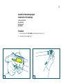
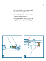
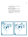
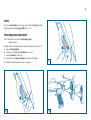
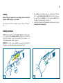
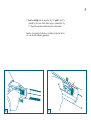
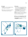
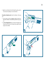
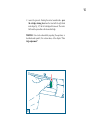
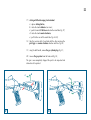
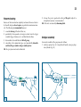
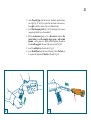
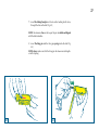
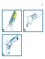
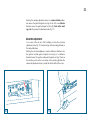
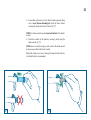
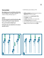
Contents
Operation ...................................................................................
Cartridge drop lever operation ....................................................
Assembly (from packaged gun) ...................................................
Safety ..........................................................................................
Telescoping stock adjustment ......................................................
Loading ......................................................................................
Cartridge replacement ................................................................
Unloading ..................................................................................
Gun stripping ..............................................................................
Firearm cleaning .........................................................................
Shotgun assembly .......................................................................
Trouble shooting .........................................................................
Choice of ammunition ................................................................
Rear sight adjustment ..................................................................
Windage adjustment ...................................................................
Elevation adjustment ...................................................................
Internal choke (when supplied) ...................................................
Three round limiter .....................................................................
1
1
2
7
7
8
11
13
15
24
24
31
31
31
31
32
33
36
SAFETY RULES
The safety warnings contained in this booklet are an important reminder to whomever owns or utilises firearms.
Firearms, if not handled correctly, can be dangerous, and have the
potential to cause serious and irreparable damage.
1) Never point a firearms at anyone, or in any direction other than a
SAFE direction, i.e., downrange.
2) Always handle firearms as if they were loaded.
9) Before using, with the gun unloaded and the action locked
open, check that the barrel of the shotgun is clear of any
obstruction.
10) Before shooting an unfamiliar gun, be sure that you understand
completely its functioning: lack of experience can be the cause
of serious accidents.
11) When firing, it is advisable to wear ear and eye protection.
12) Always keep hands and fingers away from the muzzle of the
gun, to avoid wounds or burns.
3) Keep your finger off the trigger until the target is in view.
13) Firearms and ammunition should always be stored separately,
and locked, well away from children’s reach.
4) Never fire the combat shotgun without the forearm installed,
both right and left halves.
14) Do not drink alcoholic beverages before or during the use of
firearms.
5) Keep the gun’s safety on and finger away from the trigger during
loading or unloading of the gun.
6) Before firing at the target, ensure that no person, animal, or other
object that could be hit is behind or near the target.
7) Never give or take from anyone an arm that doesn’t have the
breech open.
8) During the loading of ammunition, follow scrupulously the directions in this booklet and ensure that the ammunition is in perfect
condition.
REMEMBER:
PAY CLOSE ATTENTION TO HOW YOU HANDLE YOUR GUN:
ACCIDENTS ALMOST ALWAYS RESULT FROM FAILURE TO
OBSERVE THE FUNDAMENTAL SAFETY RULES.
1
Operation
feeding
Before attempting any work on your M4 make sure that the chamber and the magazine of your shotgun are unloaded. (See the
instructions on loading and unloading on pages 8-13).
the transference of the live cartridge from the feed mechanism in the direction of the chamber
chambering
the insertion of the live cartridge into the chamber of
the weapon
locking
the actuation of the breech mechanism that results in the
closing, and sealing, of the chamber.
The M4 shotgun is a semi-automatic, tubular magazine fed weapon
chambered for the 12 gauge (18.4 mm) shotshell cartridge. The operating system employed in this weapon is the improved ARGO (AutoRegulating Gas Operated) Twin (two gas pistons/cylinders/ports)
System with rotating bolt head with dual locking lugs.
The shotgun is now ready to be fired.
Cartridge drop lever operation
There are eight general steps in the operating cycle of M4:
firing
squeezing the trigger releases the cocked hammer which
strikes the firing pin igniting the primer and the propellant within the shell. The expanding gases exert pressure
on all sides of the shell casing, driving the projectile forward down the bore. An equal amount of force is intercepted in the gas system
unlocking
actuation of the breech mechanism that results in the
opening of the chamber
extraction removal of the cartridge case from the chamber
ejection
expulsion of the cartridge case from the weapon
cocking
the resetting of and storage of energy in the mechanism
which provides the energy needed to ignite the primer of
the live, chambered cartridge
The feeding system operates by means of a special cartridge drop
lever, the outer portion of which protrudes below the receiver and is
thus easily reached by the trigger finger.
The hammer spring forces the cartridge drop lever upwards to disengage it from the carrier latch which, pulled by the carrier latch spring,
rotates clockwise to allow a cartridge to exit from the magazine. As
the cartridge falls into position on the carrier, it presses against the
cartridge drop lever which rotates in the opposite direction to prevent
a second cartridge from exiting. The end of the cartridge drop lever
which protrudes from the receiver is marked with a red point. When
the red point is visible, the hammer is cocked and the gun is ready to
fire; otherwise the hammer is not cocked.
2
Assembly (from packaged gun)
Components of the package
stock-receiver-bolt
barrel-breech
half-fore-end
bolt handle
Procedure
1) Insert completely the bolt handle into the breech bolt unit (fig. 1);
2) unscrew the fore-end cap (fig. 2);
1
2
3
3) take the stock-receiver-bolt unit with a hand; with the other
hand, using the cocking lever, bring the bolt into open position
(until locked) (fig. 3); the cross-bolt button is set in the “fire” position.
WARNING: should the bolt fail to engage, move the cartridge drop
lever as arrowed and repeat the operation (fig. 4).
3
4
4
During this operation the bolt group should be completely assembled
and placed in the receiver, in open position (backward).
4) take the barrel-breech unit, place the barrel on the magazine
tube and slide it down toward the receiver (fig. 5);
5) insert the breech extension on the receiver, ensuring that the
magazine tube enters the opening of the barrel guide ring (fig. 6);
5
6
5
6) position the twin forearms together (fig. 7) and insert them into
the retaining band on the rear barrel;
NOTE: inserting the breech extension on the receiver be sure that it
does not strike against the bolt locking head.
7) with the barrel extension resting on the bolt head, and the bolt
head fitting into the recess formed into the barrel extension, slip
the barrel into receiver. A metallic click will indicate the barrel is
correctly seated (fig. 8).
7
8
6
8) screw on the fore-end fastening cap, on the end of the tubular
magazine and tighten firmly until the barrel and the fore grip are
locked perfectly against the receiver (fig. 9).
The chrome barrel extension must be completely contained by the
receiver. None of the chromate parts must be visible at the front of
the receiver (fig. 8).
9
9) close the bolt by pressing the special carrier control button (fig.
10).
The shotgun is now ready to be fired.
10
7
Safety
Press the safety button on the trigger guard until its red ring, indicating firing position, is no longer visible (figs. 11-12).
Telescoping stock adjustment
M4 is fitted with a two position telescoping stock:
short/extended
Starting with the telescoping stock extended and to shorten it (fig. 13):
a) depress locking button;
b) rotate the extendible stock clockwise (rear view);
c) push it forward till front stop;
d) rotate the stock counter-clockwise and release the button.
To extend the stock, follow the reverse sequence.
11
c
b
d
a
12
13
8
Loading
Before starting any operation on your shotgun, make sure that the
chamber and the magazine are unloaded!
The magazine can hold six cartridges 76 mm (3") long, or 70 mm (2"
3/4).
1) The red dot on the cartridge drop lever (indicating that the hammer is cocked) must be clearly visible. To bring lever to this position, press the carrier button (fig. 14) and open the bolt by hand,
then bring it to close position again (fig. 15);
2) with the bolt closed and the hammer cocked, reverse the gun
pointing the barrel downwards;
Loading procedure
NOTE: Make sure that the shotgun safety catch (See “Safety”, page
15) is engaged and the hammer cocked (so that the carrier latch can
retain the cartridges as they are inserted in the magazine - see
“Assembly procedure”, point 3, page 3).
WARNING: for safety reasons, verify if by opening the breech bolt
the shotgun is unloaded. Then close the breech bolt again.
14
15
9
3) insert a cartridge into the magazine (fig. 16): push it until it is
retained by the carrier latch which engages automatically (fig.
17). Repeat the operation until the magazine is fully loaded.
Now the gun cannot be fired unless a cartridge is placed in the barrel, as to one of the following procedures.
16
17
10
A) direct procedure:
1) open the bolt (fig. 18) and in the same time insert a cartridge into
the barrel through the case ejection port (fig. 19);
2) release the cocking lever: the bolt will push the cartridge on the
carrier into the chamber and stop in the closed position.
B) indirect procedure:
1) open the bolt and hold it in this position through the cocking lever. Press in the same time the cartridge drop lever, so that the
first cartridge in the magazine drops into the carrier (fig. 20);
2) release the cocking lever: the bolt will push the cartridge on the
carrier into the chamber and stop in the closed position.
WARNING: with the procedure “B” the number of cartridges in the
magazine will be reduced by one round. A new cartridge can be
inserted - see above - to fill the magazine completely.
NOTE: during this operation, always point the gun in a safe direction, even though the safety catch is engaged (see “Safety”; page 7).
Now the gun is loaded: when the safety catch is moved to firing position (red ring visible), the gun is ready for use.
18
19
11
Cartridge replacement
(this operation must be carried out with the gun safety catch
engaged - see “Safety”, page 7 and barrel pointed in a safe direction)
To replace a cartridge in the chamber, two procedures can be followed:
A) by manual replacement of a new cartridge;
B) by using the cartridge drop lever.
A) manual replacement (when the cartridge is not in the magazine)
1) reset the stock on your hip and pull the cocking lever to open the
bolt: the cartridge in the chamber is extracted and ejected from
the gun (fig. 21);
20
21
12
2) insert a new cartridge in the barrel through the ejection port (fig.
22) and release the cocking lever to reclose the bolt.
B) using the cartridge drop lever (when the cartridge is in the magazine)
1) rest the stock on your hip and open the bolt by hand: the cartridge in the chamber is extracted and ejected from the gun (fig.
23);
2) press the cartridge drop lever (fig. 24). Release the cocking lever to
reclose the bolt. In this way, the cartridge will pass quickly from the
magazine to the chamber .
22
23
24
13
Unloading
(this operation must be carried out with the gun safety catch
engaged - see “Safety”, page 7 and the barrel pointed in safe direction)
To unload the shotgun, proceed as follows:
1) open the bolt: the cartridge in the chamber will be extracted and
ejected (fig. 25);
2) close the bolt: gently releasing the clocking lever (fig. 26);
25
26
14
3) reverse the gun and - thrusting the carrier towards inside - press
the cartridge retaining lever from the front with the right hand
index finger (fig. 27); the first cartridge will come out. The carrier
latch must be pressed for each released cartridge.
WARNING: Gun can be unloaded by repeating the operation, as
described under point B, this section above, of the chapter: ”Cartridge replacement”.
27
15
Gun stripping
Before attempting any work on your M4 make sure that the chamber and the magazine of your shotgun are unloaded. (See the instructions on loading and unloading on pages 8-13).
M4 is a modular-style shotgun: no armorer tools are required for its
stripping.
Stripping procedure
1) open the bolt (fig. 28);
2) move the cartridge drop lever (fig. 29);
28
29
16
3)
4)
5)
6)
unscrew the fore-end cap (fig. 30);
remove the barrel along the magazine tube (fig. 31);
slide down the twin forearms (fig. 32);
grip the barrel and move it forward to remove the whole barrelbreech unit from the receiver (figs. 33-34);
7) hold the bolt handle firmly and press the carrier button (fig. 35),
allowing the bolt to move a little way forward until it stops (fig.
36);
30
31
17
32
33
34
35
18
8)
9)
10)
11)
12)
36
twist and pull off the bolt handle (fig. 37);
remove the bolt assembly from the receiver, pulling it forward
(fig. 38);
remove the firing pin stud from the bolt assembly, ensuring that
the firing pin and the relative return spring remain inside the
bolt (fig. 39);
remove the firing pin and the firing pin spring (fig. 40);
remove the locking head pin from its seat (fig. 41);
37
19
38
39
40
41
20
13)
14)
15)
16)
42
remove the locking head (fig. 42);
extract the axle bush from the stock-receiver unit, pushing it
with the point of the firing pin (fig. 43);
pull out the axle bush using the large end of the bolt handle
(figs. 44-45);
press the carrier button and extract the trigger group towards
the front (fig. 46);
43
21
44
46
45
22
17)
starting with the telescoping stock extended:
a) depress locking button;
b) rotate the stock clockwise (rear view);
c) push it forward till the line marked on the recoil tube (fig. 47);
d) rotate the stock counter-clockwise;
e) pull it to the rear off the recoil tube (figs. 48-49);
18)
take the receiver with a hand and with the other unscrew the
pistol grip in a counter-clockwise direction until free (fig. 50).
19)
using the bolt handle, remove the gas cylinder plugs (fig. 51);
20) remove the gas pistons from the front end (fig. 52);
The gun is now completely stripped: the parts to be inspected and
cleaned are all separated.
c
b
d
a
a
e
47
48
23
e
49
50
51
52
24
Firearm cleaning
Because of their construction simplicity and correct choice of materials, Benelli shotguns do not require any particular maintenance intervals. The following is recommended however:
1) a normal cleaning of the barrel after use;
2) periodically clean powder or foreign residues from the trigger
assembly (trigger, hammer, etc.), and then lubricate them;
3) disassemble, clean and lubricate the bolt group;
4) according to the ammunition type used, periodically dismantle
and clean the gas cylinders and gas cylinder pistons.
NB: the gas system must not be lubricated.
55
5) to keep the gun in good order, oiling of the parts subject to
atmospheric corrosion is recommended.
NB: all barrels are internally chromium plated.
Shotgun assembly
For correct assembly of the gun proceed as follows:
1) install gas pistons (fig. 55). Using the bolt handle, screw gas plugs
into cylinders (fig. 56);
56
25
2) rotate the pistol grip onto the receiver (clockwise direction from
rear sight) (fig. 57) until it is against the back end of the receiver;
then align it with the receiver (max are additional turn);
3) install the telescoping stock (figs. 58-59), following in the reverse
sequence of which it was disassembled;
4) lift the stock-receiver group as far as the receiver and press the
carrier button, insert the complete trigger group - with cocked
hammer - on the receiver in slightly forward position, then draw
it back until engaged in the rear of the receiver itself (fig. 60);
5) insert the axle bush into the hole for it (fig. 61);
6) insert the bolt head into the front of the bolt carrier (the hole on
its leg must be aligned with the slot of the bolt) (fig. 62);
57
58
26
59
60
61
62
27
7) insert the locking head pin in its hole on the locking head’s stem,
through the slot on the bolt (fig. 63);
NOTE: the reference line on the top of the pin is visible and aligned
with the bolt centerline.
8) insert the firing pin and the firing pin spring inside the bolt (fig.
64);
NOTE: always make sure that the firing pin has been inserted together with its spring.
63
64
28
9) insert the locking pin stud in its seat (fig. 65);
WARNING: if firing pin and relative locking pin have been correctly
assembled, at the end of the operation the firing pin will appear as
described under fig. 66.
NOTE: do not use any tools to insert the firing pin into the bolt carrier: use fingers only.
65
66
29
10)
hold the stock receiver almost horizontally and insert the bolt
assembly in its guide on the receiver (fig. 67);
11)
insert completely the bolt handle into the bolt group (fig. 68);
WARNING: make sure that the link slides over the trigger guard
assembly and onto the recoil spring plunger inside the receiver once
the bolt assembly is fully mounted (fig. 69).
12) open the bolt (fig. 70);
13) press the cartridge drop lever (fig. 71).
Complete gun reassembly by following procedures listed from point 4
at page 11 “Assembly procedure”.
67
68
30
69
71
70
31
Trouble shooting
Rear sight adjustment
The gun fails to fire
1) check the safety catch: if it is engaged, shift the button to the fire
position (pag. 7);
2) check that there is a cartridge in the barrel. If not, insert a cartridge
following the loading instructions (pag. 8);
The rear sight can be adjusted for both windage and elevation if the
standard factory setting does not meet shooter requirements.
Before attempting any work on your M4 make sure that the chamber and the magazine of your shotgun are unloaded.
See the instructions on loading and unloading on pages 8-13.
3) check the firing mechanism. If necessary, clean and lubricate it.
Magazine cap
1) Especially after the first rounds, check that the magazine cap is
firmly tightened, to keep the barrel against to the receiver.
Windage adjustment
Using a coin or the rim of a shell cartridge to rotate the windage
adjustment screw (fig. 72), located on the right side of the rear sight
assembly, in the desired direction.
The chrome barrel extension must be completely contained by the
receiver. None of the chromate parts must be visible at the front of
the receiver (fig. 8).
Choice of ammunition
M4 can use 12 ga. shells with 70 mm (2" 3/4) or 76 mm (3") cases.
NOTE: never use cartridges with a case longer than the chamber, as
this would have serious consequences for both the gun and shooter.
No adjustment to the shotgun is necessary to fire any of the ammunition listed above.
All Benelli shotguns are subjected to a 1370 bar burst test at the
Italian National Proof House in Gardone Valtrompia (Brescia).
72
32
Rotating the windage adjustment screw in a counter clockwise direction moves the point-of-impact on target to the left, in a clockwise
direction moves the point-of-impact to the right. Note on the windage scale, the amount of adjustment made (fig. 73).
Elevation adjustment
Use a coin or the rim of a shell cartridge to rotate the elevation
adjustment screw (fig. 74), located on top of the elevating platform, in
the desired direction.
Rotating the elevation screw in a counter clockwise direction raises
the aperture and the point-of impact of on target, in a clockwise
direction lowers the aperture and point-of-impact on target. Note on
the elevation scale on the rear surface of the elevating platform the
amount of adjustment made, or count the tactile clicks of the screw.
73
74
33
Internal choke
(when supplied)
Before attempting any work on your M4 make sure that the chamber and the magazine of your shotgun are unloaded. (See the
instructions on loading and unloading on pages 8-13).
To change or clean the internal choke, proceed as follows:
1) unscrew the internal choke using the special choke wrench supplied with the shotgun and extract it completely from the barrel
seat (fig. 75);
2) if the threaded seat of the choke on the barrel is too dirty, clean it
by spinning round the threaded part of the proper wrench (fig.
76);
NOTE: before re-using the shotgun, make sure that the choke wrench
has been removed from the barrel’s muzzle.
75
76
34
3) Reassemble on the barrel seat the kind of choke required, taking
care to insert the non-threaded part inside the barrel, before
screwing the choke on the barrel’s thread (fig. 77).
NOTE: the choke correctly mounted must not stick out of the barrel’s
muzzle.
4) Finish the assembly of the choke by screwing it firmly using the
choke wrench (fig. 78).
NOTE: before re-using the shotgun, make sure that the choke wrench
has been removed from the barrel’s muzzle.
Before the shotgun is put away, cleaning the internal choke and relative barrel thread is recommended.
77
78
35
Benelli choke tubes are marked for easy identification.
Notches on the muzzle end of each tube allow for quick
recognition, even when the choke tube is installed in the
shotgun.
A
STEEL SHOT -OK-M - ***
B
A
B
NOTCHES
SYMBOL
NOTCHES
CHOKE
SYMBOL
STEEL SHOT
I
II
III
IIII
IIIII
Full
Improved Modified
Modified
Improved Cylinder
Skeet
X
XX
XXX
XXXX
XXXXX
NO
NO
OK
OK
OK
36
Three round limiter
Before attempting any work on your M4 make sure that the chamber and the magazine of your shotgun are unloaded. (See the
instructions on loading and unloading on pages 8-13).
WARNING
The magazine spring must be captured by hand when disassembling
the gun to prevent the spring from escaping at a high velocity.
Wear eye protection when disassembling this gun!
To install the limiter, proceed as follows (figs. 79-80):
1) with the gun unloaded, point the barrel upwards and unscrew
magazine cap from the front of the weapon;
2) using relative pliers, remove magazine spring seal ring;
3) insert the limiter in the spring;
4) insert limiter and spring into the receiver (magazine tube);
5) install the spring seal ring: check for protrusion;
6) screw the magazine cap onto the end of the magazine tube and
fastening the whole barrel-breech-fore-end unit tightly.
If the magazine spring escape at high velocity severe eye injury or
other injuries can occur.
79
80