1
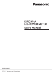
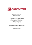
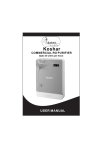
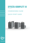
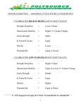
CPM-20
MULTIFUNCTION
POWER METER
diagram
CPM-20
Operation Manual
DESCRIPTION
The CPM-20 series Multifunction Power Meter provide high
accuracy measurement, display and communication(Modbus RTU)
of all electrical and power quality parameters, including harmonic
measurement THD(Total Harmonic distortion)
Provides electricity bill ratio (Cost) and carbon dioxide ratio
(Co2) set can show cumulative electricity bills and carbon
emissions, and suitable for the installation in the power
management of remote communication, such as the use of
APPLICATION
Control panels and Motor, Generator monitoring Switchgear distribution systems ,
Energy Management Power quality analysis
Front Panel
Control button:
Enter Key / Voltage /Current display page
Shift Key / Main electric parameters display page
Up Key / Electric parameters display page
Down Key/ Energy parameters display page
Passwords: 4 digits passwords;Range:0000~9999
( Default 1000)
Display: LCD 65(W)x58(H)mm ;White backlight;Blue wording
Visible under direct sunlight
LCD LED : Backlight on time1~15Min (“0” is always light)
Upper row 20 digits: Display date. time
: 4 Digitsx 4 rows, 10.0mm Display V, A, Power, Hz,PF, THD,..
: 8 Digits x 1 row, 6.0mm Display Energy parameters(kWh , kVarh)
: Rs485 communication status;2 square status icons
Display Master and Slave status;Both square on for normal communication
Load status indication: IND :load is inductive
CAP :load is capacitive
LOAD%:Display load percentage
:Display load quadrant
量測值附加符號:
a - b , b - c , c - a:When on ,value showing Line-Line
a , b , c:When on ,value showing in Phase
CSM-
:When on ,value showing in Neutral
:When on ,value showing Total value
:When on ,value showing Average
:When on ,value showing Maximun / Minimum
:When on ,value showing Total harmonics distortion
.. :LED-16 byte display parameters Unit
-1-
Installation
CSM-
Dimensions
90.0
+0 .8
CSM-321S
PANEL CUT-OUT
90.0 +0 .8
55.0
16.0
Unit: mm
2 0 1 2 -0 7 - 0 3 - 1 3 - 5 0 - 4 0
96.0
FIX HOLDERS
PANEL
CUT_OUT:
+0.8
+0.8
Total
90
Volt/Amp Harmonic
Power
(W)x90
(H) mm
User's Manual
Energy
ENTER
96.0
1.0~18.0 mm
Connection diagram
+ -
G
L
N
14151617181920 21222324
RS485 / (Terminal Block 2)
N
1A Fuse
DC100~300V
AC85~264V
N
G
G
L
RS-485
A+ B11 12
L
20
Aux. Power
L /+
N /22
24
1112 1314 1516 1718 1920 2122 2324
Fliter or isolated transformer
A+
B-
RS485 Port
111213 141516171819
Distance Max.: 1200M
Terminator: 120~300Ω/ 0.25W
(Standard: 150Ω)
V2 V3
4
5
6
7
8
9
1
10
Vn I11 I12 I21 I22 I31 I32
A
B
C
N
V1
V2 V3
4
5
6
7
8
9
V2 V3
4
5
6
7
8
9
10
Vn I11 I12 I21 I22 I31 I32
A
B
C
N
10
1
Vn I11 I12 I21 I22 I31 I32
V1
SOURCE
A
B
C
N
3
LOAD
SOURCE
V1
2
3
]
3 P 4 W Balanced load – Direct Voltage(No PT)
/ 1CT [ SET: 3 p 4 W b]
3 P 4 W Balanced load– 3PT / 1CT [ SET: 3 p 4 W b]
1
2
3p4w
LOAD
3
LOAD
SOURCE
V1
2
3 P4 W– Direct voltage (No PT) / 3CT [ SET :
]
SOURCE
1
3p4w
-2-
A
B
C
N
2
3
V2 V3
4
5
6
7
8
9
10
Vn I11 I12 I21 I22 I31 I32
LOAD
3 P4 W – 3PT / 3CT [ SET :
Connection diagram
3 P 3 W – 2PT / 2CT [ SET :
5
6
7
8
9
10
1
Vn I11 I12 I21 I22 I31 I32
A
B
C
2
3
4
5
6
7
8
9
4
5
6
7
8
9
10
Vn I11 I12 I21 I22 I31 I32
A
B
C
3 P 3 W Balanced load– Direct Voltage (No PT)
/ 1CT [ SET: 3 p 3 W b]
1
10
SOURCE
LOAD
A
B
C
2
V1
V 1 V2 V3 Vn I11 I12 I21 I22 I31 I 32
SOURCE
3
V2 V3
V1
3 P 3 W– (No PT) / 3CT [ SET: 3 p 3 W 3]
1
2
LOAD
V2 V3
4
LOAD
SOURCE
V1
3
3p3w
3
V2 V3
4
5
6
7
8
9
10
Vn I11 I12 I21 I22 I31 I32
A
B
C
LOAD
2
3 P3 W – Direct Voltage (No PT) / 2CT [ SET :
]
SOURCE
1
3p3w
3P3W – 2PT / 3CT [ SET: 3 p 3 W 3]
1
2
4
V2 V3
V1
5
6
7
8
9
10
Vn I11 I12 I21 I22 I31 I32
A
B
C
LOAD
1P3W – [ SET :1 p 3 w ]
1P2W – [SET: 1 p 2 w ]
A
N
3
V2 V3
4
5
6
7
8
9
1
10
V1
Vn I11 I12 I21 I22 I31 I32
SOURCE
SOURCE
V1
2
LOAD
1
- 3-
A
N
B
2
3
V2 V3
4
5
6
7
8
9
10
Vn I11 I12 I21 I22 I31 I32
LOAD
SOURCE
3
]
Operational processes
Key definition:
ENT:Enter / Volt.( Voltage )/AMP.( current )
Shift:Shift left /Total(Comprehensive)
Up: Move Up /Power
Down: Move Down /Energy
Confirm wiring
Power transmission
Display
Models and versions
Press
1 Sec back operation display
2 0 1 2 -0 7 - 0 3 - 1 3 - 5 0 - 4 0 Phase voltage and the Average
Phase A voltage
Permanent Mission of
the screen display
a
Phase B voltage
b
2 0 1 2 -0 7 - 0 3 - 1 3 - 5 0 - 4 0
Phase C voltage
c
l-n
Average Phase voltage (Avg/V) ,
Effective energy(kWh)
Press
Key
1 Sec
Press
Key
P.COD
Default:1000
Press
Key
Password
Correct
Parameter setting class
2 0 1 2 -0 7 - 0 3 - 1 3 - 5 0 - 4 0
General operating class
The permanent
screen Please refer
to the H-1 set Item
Description
Press
Press
Key
key into each group
Voltage, Current, Total
harmonic display group
Press
Key
Integrated display group
Press
Key
Power display group
Press
Key
Electricity, Time display group
A1~A6 Input group
▲KEY
▼KEY
E1~E3 RS485 group
▲KEY
▼KEY
F1~F2 Energy group
▲KEY
▼KEY
G1~G3 Time group
YES
NO
-4-
Press ENT Key (Voltage and Current harmonics screen)
2 0 1 2 -0 7 - 0 3 - 1 3 - 5 0 - 4 0
Normal screen
1 seconds,
first showed off the voltage value As follows
2 0 1 2 -0 7 - 0 3 - 1 3 - 5 0 - 4 0 Phase voltage and the Average
Phase A voltage
a
Phase B voltage
b
a
Phase A current
b
Phase B current
c
Phase C current
Neutral Current(N)
N
Phase C voltage
c
1.1.4- Phase Current and
Neutral
Current
Average Phase voltage (Avg/V) ,
Effective energy(kWh)
Effective energy(kWh)
Press
Press
Key
Key
2 0 1 2 -0 7 - 0 3 - 1 3 - 5 0 - 4 0
1.1.1- The Value of the Line voltage
and the Average Line voltage
2 0 1 2 -0 7 - 0 3 - 1 3 - 5 0 - 4 0 1.1.5- Current harmonic distortion rate
THDI/ Phase A Current THD
a-b
A-B Line Voltage
a
b-c
B-C Line Voltage
b
c-a
C-A Line Voltage
Average line voltage(Avg/V)
THDI/ Phase B Current THD
THDI/ Phase C Current THD
c
%
Effective energy(kWh)
Press
Press
Key
2 0 1 2 -0 7 - 0 3 - 1 3 - 5 0 - 4 0 1.1.2- Voltage total harmonic distortion
a
Phase voltage total harmonic
THDU/ Phase A THD(%)
b
THDU/ Phase B THD(%)
THDU/ Phase C THD(%)
c
%
Average line voltage THD (Avg/%)
Effective energy(kWh)
Press
Key
2 0 1 2 -0 7 - 0 3 - 1 3 - 5 0 - 4 0
1.1.3- Phase current values and the
average
Phase A current
a
b
Phase B current
c
Phase C current
Average current(Avg/A)
Effective energy(kWh)
Press
Key
-5-
Average Current THD (Avg/%)
Effective energy(kWh)
Key
To 1.1.1 Display Or
Press
Key1 Sec Back to
Measurement screen
Up KEY (Power Parameters)
Shift KEY (Comprehensive screen) Press
Press
Normal screen
1 seconds,
first showed off the voltage value As follows
Normal screen
1 seconds,
first showed off the voltage value As follows
2 0 1 2 -0 7 - 0 3 - 1 3 - 5 0 - 4 0 Phase voltage and the Average
2 0 1 2 -0 7 - 0 3 - 1 3 - 5 0 - 4 0
Phase A voltage
a
a
Phase B voltage
b
Phase B voltage
b
Phase C voltage
c
Phase C voltage
c
Average Phase voltage (Avg/V) ,
Average Phase voltage (Avg/V) ,
Effective energy(kWh)
Effective energy(kWh)
Press
Key
Press
2 0 1 2 -0 7 - 0 3 - 1 3 - 5 0 - 4 0
1.2.1- 3-phase integrated display-1
Average Phase voltage ( L-n)
l-n
Key
2 0 1 2 -0 7 - 0 3 - 1 3 - 5 0 - 4 0
a
b
Total Effective power ( kW)
c
Key
Phase C active power
Total Effective power ( kW)
Effective energy ( kWh)
Press
2 0 1 2 -0 7 - 0 3 - 1 3 - 5 0 - 4 0
1.2.2- 3-phase integrated display-2
Average Line voltage ( L-L)
Key
2 0 1 2 -0 7 - 0 3 - 1 3 - 5 0 - 4 0
Phase B reactive power
Average current ( A)
b
Total Effective power ( kW)
Phase C reactive power
c
Total reactive power ( kvar)
Invalid electricity ( kvarH)
Average power factor (PF/IND/Avg)
Effective energy(kWh)
Key
Press
2 0 1 2 -0 7 - 0 3 - 1 3 - 5 0 - 4 0
1.3.2- Reactive power display
Phase A reactive power
a
l-l
Press
1.3.1- Effective power display
Phase A active power
Phase B active power
Average current ( A)
Average power factor (PF/IND/Avg)
Effective energy(kWh)
Press
Phase voltage and the Average
Phase A voltage
1.2.3- 3-phase integrated display-3
Total Apparent Power ( VA)
Key
2 0 1 2 -0 7 - 0 3 - 1 3 - 5 0 - 4 0
1.3.3- Apparent power display
Phase A apparent power
a
Phase B apparent power
Total Reactive Powe r ( Var)
b
Total Effective power ( W)
Phase C apparent power
c
Total Apparent Power ( kVA)
Effective energy ( kWh)
Average power factor (PF/IND/Avg)
Effective energy ( kWh)
Total
Press
Key
Press
2 0 1 2 -0 7 - 0 3 - 1 3 - 5 0 - 4 0
1.2.4- 3-phase integrated display-4
Total Apparent Power ( VA)
Key
2 0 1 2 -0 7 - 0 3 - 1 3 - 5 0 - 4 0
a
Phase B power factor
Total Reactive Powe r ( Var)
b
Total Effective power ( W)
c
Phase C power factor
Freq
Press
Average Power factor ( PF/IND/Avg)
Effective energy ( kWh)
Frequency ( Hz)
Effective energy ( kWh)
Total
Key
Press
To 1.2.1 Display Or
Press
1.3.4- Power Factor display
Phase A power factor
Key1 Sec Back to
Measurement screen
-6-
Key
To 1.3.1 Display Or
Press
Key1 Sec Back to
Measurement screen
Down KEY (Power parameters)
Press
Normal screen
1 seconds,
first showed off the voltage value As follows
2 0 1 2 -0 7 - 0 3 - 1 3 - 5 0 - 4 0 Phase voltage and the Average
Phase A voltage
a
Phase B voltage
b
Phase C voltage
c
Average Phase voltage (Avg/V) ,
Effective energy(kWh)
Press
Key
2 0 1 2 -0 7 - 0 3 - 1 3 - 5 0 - 4 0
1.4.1- Power display-1
Total apparent power ( VA)
Total reactive power ( Var)
Total effective power ( W)
Average power factor (PF/IND/Avg)
Total Effective energy ( kWh)
Total
Press
Key
2 0 1 2 -0 7 - 0 3 - 1 3 - 5 0 - 4 0
1.4.2- Power display-2
Total apparent power ( VA)
Total reactive power ( Var)
Total effective power ( W)
Average power factor (PF/IND/Avg)
Total invalid electricity ( kvarH)
Total
Press
Key
2 0 1 2 -0 7 - 0 3 - 1 3 - 5 0 - 4 0
1.4.3- Total electricity bills display
Total apparent power ( kVA)
Total reactive power ( kvar)
Total effective power ( kW)
Average power factor (PF/IND/Avg)
Total electricity bill ($)
Total
Press
Key
1.4.4- Carbon emissions
Total apparent power ( kVA)
Total reactive power ( kvar)
Total effective power ( kW)
Average power factor (PF/IND/Avg)
Total carbon dioxide ( CO2/kg)
Press
Key
To 1.4.1 Display Or
Press
Key1 Sec Back to
Measurement screen
-7-
set class, non-personnel do not arbitrarily enter the change,
*inEngineers
order to avoid abnormal。
INPUT Group
Operation display
Press
2 0 1 2 -0 7 - 0 3 - 1 3 - 5 0 - 4 0
2 0 1 2 -0 7 - 0 3 - 1 3 - 5 0 - 4 0
Key Enter the setup menus
Password
0000~9999
A-5 Watt-h / Var Clear
ClearPasswords:
0000~9999
Zero password please call
the company to ask.
Default:1000
▼KEY
2 0 1 2 -0 7 - 0 3 - 1 3 - 5 0 - 4 0
A-1 Voltage Phase line set
2 0 1 2 -0 7 - 0 3 - 1 3 - 5 0 - 4 0
Set range is as follows:
1P2W/1P3W/3P3W/
3P3W.B (Balanced)/3P3W3/
3P4W/3P4W.B (Balanced)
Default:3P4W
2 0 1 2 -0 7 - 0 3 - 1 3 - 5 0 - 4 0
A-2 Primary-side voltage (PT)
Set range :100~500000V
A-6 P.COD
Set range :
0000~9999
Default:1000
2 0 1 2 -0 7 - 0 3 - 1 3 - 5 0 - 4 0 Rs485 Group
E-1 Communication
station No.
Set range :001~255
Default:600
2 0 1 2 -0 7 - 0 3 - 1 3 - 5 0 - 4 0
A-3 Secondary-side voltage (PT)
Set range :100~600V
2 0 1 2 -0 7 - 0 3 - 1 3 - 5 0 - 4 0
transmission rate
Set range :
1200、2400、4800、
9600、19200、38400
Default:600
2 0 1 2 -0 7 - 0 3 - 1 3 - 5 0 - 4 0
A-4 Primary current (CT)
Set range :5~10000A
E-2 Communications
2 0 1 2 -0 7 - 0 3 - 1 3 - 5 0 - 4 0
E-3 Parity Check
Set range :n.8.1、
n.8.2、o.8.1、e.8.1
Default:5
-8-
Default:n.8.2
NEXT
2 0 1 2 -0 7 - 0 3 - 1 3 - 5 0 - 4 0 ENEGY Group
2 0 1 2 -0 7 - 0 3 - 1 3 - 5 0 - 4 0
F-1 Tariff rates
Set range :
00.00~99.99
H-1 Permanent screen
selection
Set range :1~4
(one dollar/kWh)
Schedule Description
Default:2.30
▼KEY
2 0 1 2 -0 7 - 0 3 - 1 3 - 5 0 - 4 0
Back To A-1 Display Or
F-2 CO 2 Carbon ratio
Set range :
0.000~9.999(kg/kWh)
Press
Key1 Sec Back to
Measurement screen
Schedule: The Permanent screen instructions
Default:0.638
2 0 1 2 -0 7 - 0 3 - 1 3 - 5 0 - 4 0
The first
TIME Group
G-1 Backlight time
Set range :0~15 (Minute)
Set 0 for Always
The second
Default:1
2 0 1 2 -0 7 - 0 3 - 1 3 - 5 0 - 4 0
2 0 1 2 -0 7 - 0 3 - 1 3 - 5 0 - 4 0
G-2 Date set
Set range :
2000.01.01~2099.12.31
The third
The fourth
G-3- Time set
Set range :
00.00.00~23.59.59
-9-
RS485 communication parameters address table
(Function code: 03h, 06h, 10h)
General class information
Data Name Register address
Frequency
Average
phase
voltage
U l lavg
I avg
In
Psum
Qsum
Ssum
PF avg
Ea
Er
Cost
CO 2
UA
UB
UC
UAB
UBC
UCA
IA
IB
IC
PA
PB
PC
QA
QB
QC
SA
SB
SC
PFA
PFB
PFC
LT
0000h
0001h
0002h
0003h
0004h
0005h
0006h
0007h
0008h
0009h
000Ah
000Bh
000Ch
000Dh
000Eh
000Fh
0010h
0011h
0012h
0013h
0014h
0015h
0016h
0017h
0018h
0019h
001Ah
001Bh
001Ch
001Dh
001Eh
001Fh
0020h
0021h
0022h
0023h
0024h
0025h
0026h
0027h
0028h
0029h
002Ah
002Bh
002Ch
002Dh
002Eh
002Fh
0030h
0031h
0032h
0033h
0034h
0035h
0036h
0037h
0038h
0039h
003Ah
003Bh
003Ch
003Dh
003Eh
003Fh
Data Format
XXXX
XX.XX
XXXX
XXX.X
XXXX
XXX.X
XXXX
X.XXX
XXXX
X.XXX
XXXX
XXXX
XXXX
XXXX
XXXX
XXXX
XXXX
X.XXX
XXXX
XXX.X
XXXX
XXX.X
XXXX
XXX.X
XXXX
XXX.X
XXXX
XXX.X
XXXX
XXX.X
XXXX
XXX.X
XXXX
XXX.X
XXXX
XXX.X
XXXX
XXX.X
XXXX
X.XXX
XXXX
X.XXX
XXXX
X.XXX
XXXX
XXXX
XXXX
XXXX
XXXX
XXXX
XXXX
XXXX
XXXX
XXXX
XXXX
XXXX
XXXX
XXXX
XXXX
XXXX
XXXX
XXXX
XXXX
X.XXX
0040h
XXXX
0041h
X.XXX
0042h
XXXX
0043h
X.XXX
0044h
XXXX
Data
Length
Measurement range
Unit
R/W
2
45.00 ~65.00
Hz /100
R
2
0~500000.0
V/10
R
2
0~500000.0
V/10
R
2
0~10000.000
A /1000
R
2
0~10000.000
A /1000
R
2
-999999999 ~999999999
W
R
2
-999999999 ~999999999
var
R
VA
R
2
-999999999 ~999999999
PF
/1000
kWh
/10
kvarH
/10
R/W
0~9999999.9
$/10
R
2
0~9999999.9
kg/10
R
2
0~500000.0
V/10
R
2
0~500000.0
V/10
R
2
0~500000.0
V/10
R
2
0~500000.0
V/10
R
2
0~500000.0
V/10
R
2
0~500000.0
V/10
R
2
0~10000.000
A/1000
R
2
0~10000.000
A/1000
R
2
0~10000.000
A/1000
R
2
-999999999 ~999999999
W
R
2
-999999999 ~999999999
W
R
2
-999999999 ~999999999
W
R
2
-999999999 ~999999999
var
R
2
-999999999 ~999999999
var
R
2
-999999999 ~999999999
var
R
2
-999999999 ~999999999
VA
R
2
-999999999 ~999999999
VA
R
2
-999999999 ~999999999
2
-1.000 ~1.000
2
0~9999999.9
2
0~9999999.9
2
R
R/W
VA
R
R
2
-1.000 ~1.000
PF/
1000
2
-1.000 ~1.000
PF/
1000
R
2
-1.000 ~1.000
PF/
1000
R
1
82=R, 76=L, 67=C
Default Information
Frequency ( high word )
Frequency ( low word )
Average phase voltage( high word )
Average phase voltage ( low word )
Average line voltage( high word )
Average line voltage( low word )
Average current( high word )
Average current( low word )
Neutral current( high word )
Neutral current( low word )
Total effective power( high word )
Total effective power( low word )
Total reactive power( high word )
Total reactive power( low word )
Total apparent power( high word )
Total apparent power( low word )
Average power factor( high word )
Average power factor( low word )
Effective energy( high word ), over 9999999.9 a uto Zero
Effective energy( low word ), over 9999999.9 a uto Zero
Invalid electricity( high word ), over 9999999.9 a uto Zero
Invalid electricity( low word ), over 9999999.9 a uto Zero
Total electricity bill( high word ), over 9999999.9 a uto Zero
Total electricity bill( low word ), over 9999999.9 a uto Zero
The total carbon dioxide(high word),over 9999999.9 a uto Zero
The total carbon dioxide(low word),over 9999999.9 a uto Zero
Phase A voltage( high word )
Phase A voltage( low word )
Phase B voltage( high word )
Phase B voltage( low word )
Phase C voltage( high word )
Phase C voltage( low word )
AB line voltage( high word )
AB line voltage( low word )
BC line voltage( high word )
BC line voltage( low word )
CA line voltage( high word )
CA line voltage( low word )
Phase A current( high word )
Phase A current( low word )
Phase B current( high word )
Phase B current( low word )
Phase C current( high word )
Phase C current( low word )
Phase A active power( high word )
Phase A active power( low word )
Phase B active power( high word )
Phase B active power( low word )
Phase C active power( high word )
Phase C active power( low word )
Phase A reactive power( high word )
Phase A reactive power( low word )
Phase B reactive power( high word )
Phase B reactive power( low word )
Phase C reactive power( high word )
Phase C reactive power( low word )
Phase A apparent power( high word )
Phase A apparent power( low word )
Phase B apparent power( high word )
Phase B apparent power( low word )
Phase C apparent power( high word )
Phase C apparent power( low word )
Phase A Power Factor( high word )
Phase A Power Factor( low word )
Phase B Power Factor( high word )
Phase B Power Factor( low word )
Phase C Power Factor( high word )
R
- 10 -
Phase C Power Factor( low word )
Load characteristics , R:Resistive, L:Inductive ,
C:Capacitive
General class information
Data Name Register address
Data Format
Data
Measurement range
Length
Unit
R/W
Default Information
THDUAB
0045h
XXX.X
1
0~100.0
%/10
R
AB line voltage total harmonic
THDUBC
0046h
XXX.X
1
0~100.0
%/10
R
BC line voltage total harmonic
THDUCA
0047h
XXX.X
1
0~100.0
%/10
R
CA line voltage total harmonic
THDUavg
0048h
XXX.X
1
0~100.0
%/10
R
Average voltage total harmonic
THDIA
0049h
XXX.X
1
0~100.0
%/10
R
Phase A current total harmonic
THDIB
004Ah
XXX.X
1
0~100.0
%/10
R
Phase B current total harmonic
THDIC
004Bh
XXX.X
1
0~100.0
%/10
R
Phase C current total harmonic
THDIavg
004Ch
XXX.X
1
0~100.0
%/10
R
Average total harmonic current
Unit
R/W
Input group setting class
Data Name Register address
Voltage
wiring
Wire-U
Data Format
Data
Measurement range
Length
004Dh
X
1
0~6
PT- Pri
004Eh
004Fh
XXXX
XXXX
2
100~500000
PT- Sec
0050h
XXXX
1
CT- Pri
0051h
XXXX
P.code
0052h
XXXX
Default Information
0:1P2W
1:1P3W
2:3P3W
3:3P3W.B
4:3P3W.3
5:3P4W
6:3P4W.B
R/W
5
V
R/W
600
PT Primary side voltage setting( high word )
PT Primary side voltage setting( low word )
100~600
V
R/W
600
PT Secondary voltage settings
1
5~10000
A
R/W
50
1
0000~9999
R/W
CT Primary current setting
1000 Clearance password change
RS485 communication group settings class
Data Name Register address
Data Format
Data
Measurement range
Length
Unit
R/W
Default Information
Addr
0053h
XXX
1
1~255
R/W
1
The Communication Station No. setting
Baud
0054h
X
1
0~5
R/W
3
0:1200 , 1:2400 , 2:4800 , 3:9600 , 4:19200 , 5:38400
Parity
0055h
X
1
0~3
R/W
1
0:N81 , 1:N82 , 2:O81 , 3:E81
Cost group setting class
Data Name Register address
Data Format
Data
Length
Measurement range
Unit
R/W
Default Information
Cost
0056h
XX.XX
1
00.00~99.99
R/W
2.30
CO2
0057h
X.XXX
1
0.000~9.999
R/W
0.638 kWh of carbon dioxide ratio setting
- 11 -
kWh the cost ratio setting
Time group settings class
Data Name Register address
Data Format
Data
Measurement range
Length
Unit
R/W
Default Information
BackLight
0058h
XX
1
0~15
R/W
1
Year
Month
Day
Time
Minute
Second
0059h
005Ah
005Bh
005Ch
005Dh
005Eh
XXXX
XX
XX
XX
XX
XX
1
1
1
1
1
1
0~99 = 2000~2099
1~12
1~31
0~23
0~59
0~59
R/W
R/W
R/W
R/W
R/W
R/W
2012
1
1
0
0
0
0/1~15Minute, 0 minutes representatives never light up
Permanent screen group settings class
Data Name Register address
Data Format
Data
Length
Measurement range
Unit
R/W
Default
Information
1: 1.2.1 : Average phase voltage(T/L-n/V) / Average current (A)/ Total effective power(kW)
Average power factor(PF/IND/Avg) / Total effective energy(kWh)
Def.Page
005Fh
XXXX
1
1~4
R/W
1
2: 1.2.2 : Average line voltage(T/L-L/V) / Average current (A)/ Total effective power(kW)
Average power factor(PF/IND/Avg) / Total effective energy(kWh)
3: 1.2.3 : Total apparent power(T/kVA) / Total reactive power(kvar)/ Total effective power
(kW)/ Average power factor(PF/IND/Avg) / Total effective energy(kWh)
4: 1.2.4 : Total apparent power(T/kVA) / Total reactive power(kvar)/ Total effective power
(kW)/ Frequency(Hz) / Total effective energy(kWh)
- 12 -