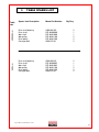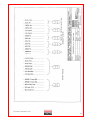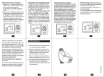
1
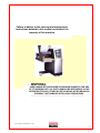
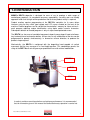
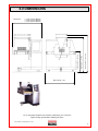
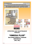
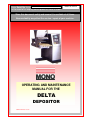
Enter Serial No. here.
In the event of an enquiry please quote this serial number.
MANUAL No.Y-DE-01E
Store this document safely and ensure it is available at all times.
Non-availability may affect the service / repair of your machine.
OPERATING AND MAINTENANCE
MANUAL FOR THE
DELTA
DEPOSITOR
SOFTSTART 2007 version
FG073 DELTA DEPOSITOR 04-05 RAC
FG073 DELTA (SOFTSTART) 08-11 RAC
2
Failure to adhere to the cleaning and maintenance
instructions detailed in this manual could affect the
warranty of this machine.
DISPOSAL
CARE SHOULD BE TAKEN WHEN THE MACHINE COMES TO THE END
OF ITS WORKING LIFE. ALL PARTS SHOULD BE DISPOSED OF IN THE
APPROPRIATE PLACE, EITHER BY RECYCLING OR OTHER MEANS OF
DISPOSAL THAT COMPLIES WITH LOCAL REGULATIONS.
(IN UK, ENVIRONMENTAL PROTECTION ACT 1990 APPLIES)
FG073 DELTA (SOFTSTART) 08-11 RAC
3
INDEX
1.0
2.0
3.0
4.0
5.0
6.0
7.0
INTRODUCTION
DIMENSIONS
SPECIFICATIONS
SAFETY
INSTALLATION
ISOLATION
CLEANING INSTRUCTIONS
Between mix changes
Table removal and cleaning
8.0
9.0
OPERATING CONDITIONS
OPERATING INSTRUCTION
Fitting the hopper
Fitting a non-rotary template
Fitting a rotary template
10.0 CONTROL PANEL (Key diagram)
11.0 DESCRIPTION OF CONTROL PANEL FUNCTIONS
12.0 OPERATIONAL CONTROLS
Start button
Stop button
Prime button
Auto button
Manual button
13.0 PREPERATION FOR OPERATION
14.0 MACHINE / PRODUCT PROGRAMMING (see separate manual)
15.0 MAINTENANCE
1.Resettable miniature contact breakers
2.Lubrication
3.Air filter replacement
16.0 SPARES AND SERVICE
17.0 RECOMMENDED SPARES LISTS
1.Electrical
2.Base machine spares
3.Table spares
4.Hopper spares
18.0 ELECTRICAL DIAGRAMS
FG073 DELTA (SOFTSTART) 08-11 RAC
4
1.0 INTRODUCTION
MONO’s DELTA depositor is designed for ease of use to produce a wide range of
confectionery products. Its exceptional accuracy, repeatability, versatility and user friendly
approach lends itself to high volume production and to where product variety is required.
Product creation requires programming of the DELTA’s controller via its menu driven
interface using the key switch type keypad and LCD screen situated on the front of the
machine. Product programs can be stored into the controller’s memory for future retrieval –
each program requiring unique identification using alpha and/or numeric characters.
Subsequent deletion of created programs is only via a password-protected screen.
The DELTA has four axes of controlled movement; deposit pump, deposit head raise/lower,
tray horizontal travel and nozzle rotation. All four axes or any combination of the four can be
programmed to operate simultaneously, in forward or reverse direction, to produce the
product shape required.
Mechanically, the DELTA is configured with the depositing head capable of vertical
movement and the tray conveyor in a fixed height position. This combination permits the
siting of the DELTA over existing conveyor production lines with minimal modification.
SCREEN
KEYS
STOP
In order to achieve smooth production and optimum performance, it is recommended
that the information given in this manual be studied before any operation is carried out.
FG073 DELTA (SOFTSTART) 08-11 RAC
5
2.0 DIMENSIONS
MAX HEIGHT = 1485 mm
MIN HEIGHT = 1370 mm
= 1193mm (580mm HOPPER)
= 1063mm (450mm HOPPER)
= 1013mm (400mm HOPPER)
TABLE HEIGHT = 825 mm
MAX WIDTH
MAX LENGTH = 1225
As it is our policy to improve our machines continuously, we reserve the
right to change specifications without prior notice.
FG073 DELTA (SOFTSTART) 08-11 RAC
6
3.0
SPECIFICATIONS (soft dough)
MODEL (Nominal Hopper Width)
40
45
58
WEIGHT
388
390
396
Maximum Deposit Rate (litre/minute)
26
30
40
Maximum Single Deposit (litre)
8.5
9.5
12
Standard Hopper Capacity (litre)
36
41
53
(Kg)
Maximum Vertical Travel
:
110mm
Minimum Distance Between Trays
:
50mm
POWER
:
2.5 Kw SINGLE PHASE FUSED AT 20A.
Anti-surge or 20A type D MCB.
Electronics
:
All microprocessor controlled
Noise Level
:
Less than 85dB
NOTE
The minimum deposit that can be made depends on several factors,
•
Recipe - mixing method - template size and deposit speed.
As a guide the following is the minimum that should be attempted.
macaroons
6g
meringues
3g,
choux paste
5g
Viennese
4g,
sponge drops
4g
However, consult Mono Equipment if intended product falls outside the above general
machine specification to determine the DELTA’s exact capabilities with any specific product.
As it is our policy to improve our machines continuously,
we reserve the right to change specifications without prior notice.
FG073 DELTA (SOFTSTART) 08-11 RAC
7
4.0
SAFETY
1
Never use a machine in a faulty condition and always report any damage.
2
Only trained engineers may remove any part from this machine that requires a
tool to do so.
3
Always ensure hands are dry before touching any electrical appliance
(including cable, switch and plug).
4
All operatives must be fully trained.
5
People undergoing training on the machine must be under direct supervision.
6
Do not operate the machine with any panels or guards removed.
7
No loose clothing or jewellery should be worn while operating the machine.
8
Switch off power at the mains isolator when machine is not in use and before
carrying out any cleaning or maintenance.
ALL CLEANING AND MAINTENANCE OPERATIONS MUST BE MADE WITH
MACHINE DISCONNECTED FROM THE POWER SUPPLY.
9
The bakery manager or the bakery supervisor must carry out daily safety
checks on the machine.
10
Do not operate machine without hopper template fitted correctly.
TEMPLATE CORRECTLY FITTED
TO HOPPER
5.0
INSTALLATION
1
Ensure that the depositor is connected to the correct electric supply as specified
on the serial number plate on the rear of the machine.
2
Ensure that the correct fuse rating is fitted in the electrical supply to the DELTA
a 13A single phase supply fused at 20A anti-surge or 20A type D MCB is
required.
FG073 DELTA (SOFTSTART) 08-11 RAC
8
6.0
1
ISOLATION
In an emergency, switch off at the mains wall isolator, or the machine’s
emergency stop button. To release the emergency stop button, turn clockwise.
EMERGENCY
STOP BUTTON
7.0
CLEANING INSTRUCTIONS
NOTE:
-Cleaning must be carried out by fully trained personnel only.
-Isolate machine from mains supply before carrying out any cleaning.
-Do not steam clean or use a jet of water,
except in the rotary template drive gear compartment
All the outer surfaces of the machine should be wiped over with warm soapy water.
Do not use any form of caustic detergent or abrasive.
BETWEEN PRODUCT MIX CHANGES
1
The hopper, hopper pump, template, nozzles etc should be removed from the
machine and dismantled for thorough cleaning.
2
Prior to removing the hopper or template, the guards must be hinged up and
propped into the appropriate position.
3
Slacken template clamp strip nuts and remove fitted template from hopper
pump assembly by sliding out to avoid subsequent damage.
4
To reduce weight and bulk, separate and remove hopper body from hopper
pump assembly whilst still on the machine. Unscrew the nuts holding the
hopper body to the hopper pump to reveal the ‘0’ sealing ring. Ensure seal is
not damaged during cleaning.
5
Unscrew hopper retaining pin and remove hopper pump assembly from
machine to separate cleaning area.
ROTARY TEMPLATE
DRIVE
FRONT AND REAR GUARDS
HINGED UP
HOPPER RETAINING PIN
FG073 DELTA (SOFTSTART) 08-11 RAC
9
CAUTION SHOULD BE TAKEN WHEN REMOVING HOPPER ASSEMBLY AS
WEIGHT EXCEEDS 25KGS.
6
Unscrew the nuts holding the pump end cap to the hopper. Ensure that the nuts
are placed where they will not be lost.
7
Withdraw the end cap with the pump gears, if still attached. Ensure that the ‘0’
sealing ring on the inside of the endplate is not damaged during cleaning.
NOTE: Use only warm soapy water to clean these parts that should be rinsed and
thoroughly dried before reassembly. The greatest care must be taken not to
drop the hopper, or leave any components in the hopper. After washing, the
component parts should be allowed to cool before attempting reassembly.
8
Reassembly is reversal of above procedure.
TABLE REMOVAL AND CLEANING
1
Removal of the table from the machine for cleaning is not necessary, however,
if required, unscrew the two securing screws from the side of the table and
slide table off support bars - the drive shaft will disengage from its coupling as
the table is removed.
To replace, follow reverse procedure ensuring drive shaft engages properly with
its coupling.
2
In normal use clean the table’s external surfaces and belts with warm soapy
water and rinse and thoroughly dry before use.
3
The table’s conveyor belts can be disengaged from their drive rollers by
slackening the adjusting screws on the underside of the table. However, for belt
replacement first remove the table from machine as in 1 above.
END CAP O-RING
TABLE DRIVE COUPLING
TABLE RETAINING
SCREWS
BOLT ADJUSTING SCREWS
FG073 DELTA (SOFTSTART) 08-11 RAC
10
8.0
OPERATING CONDITIONS
Make sure the depositor is used on a level floor to achieve best results.
Ensure flat trays of consistent length, width, material and edge dimensions are used to
obtain the best product results and consistent operating from the DELTA.
9.0
OPERATING INSTRUCTIONS
FITTING THE HOPPER
CAUTION SHOULD BE TAKEN WHEN FITTING HOPPER PUMP AS WEIGHT
EXCEEDS 25KGS.
1
Hinge up front and rear hopper guards and prop up.
To reduce weight and bulk, fit the complete hopper assembly in two stages
- first the hopper pump assembly, then the hopper body with its detachable top guard.
2
Align hopper pump drive gear with drive shaft and slide hopper on support bars
until fully up against bulkhead. Screw in hopper retaining screw once the hopper
is positioned correctly.
DO NOT OPERATE MACHINE WITHOUT TEMPLATE FITTED.
Hopper pump drive shaft alignment
FITTING A NON-ROTARY TEMPLATE
1
Hinge up front and rear hopper guards and prop up.
2
Select template and nozzles required.
3
Screw nozzles into threaded nozzle tube on templates.
4
Slide template into matching recess at base of hopper pump until the stop
engages.
5
Tighten nuts on clamp strip on underside of hopper pump to secure template.
Leakage of mix will occur if the nuts are not securely tightened.
6
Lower front and rear hopper guards.
FG073 DELTA (SOFTSTART) 08-11 RAC
11
FITTING OF ROTARY TEMPLATES
These units are used for the manufacture of circular products.
The straight rotary holder(s) are used, for whirls.
Offset rotary holder(s) are used for such products as meringue rings.
1
Hinge and prop up front and rear hopper guards
2
Select template, nozzle holder and nozzle required.
3
Screw nozzles into offset or straight rotary holder.
4
Insert nozzle holder into template ensuring that they are pushed fully into
seatings.
5
Slide template into matching recess at base of hopper pump until gear teeth
mesh (i.e. stop on template abutting hopper end cap).
If gear teeth of template fail to mesh at first attempt, lower front and rear hopper
guards and press start. To rotate the drive gear press then the green
button (14).
Retry full engagement of template after re-hinging and popping up front and rear
hopper guards to gain access.
6
Tighten nuts on underside of hopper to secure template. Leakage of mix will
occur if the nuts are not securely tightened.
7
If offset-nozzle holder has been fitted to template check alignment of all nozzles
with each other and with axis of template (this may be critical for some products
and / or to avoid collision of nozzle holders whilst rotating). Adjust position by
twisting holder in its template tube.
8
Lower front and rear hopper guards.
Rotary template and
standard accessories
Alignment of offset holders in rotary template
FG073 DELTA (SOFTSTART) 08-11 RAC
12
10.0
DELTA CONTROL PANEL
(1-4)
(5-8)
(15)
(16)
(9)
(19)
(10)
(17)
(18)
(13)
(11)
(12)
(14)
Fig. 10. DELTA Control panel
FG073 DELTA (SOFTSTART) 08-11 RAC
13
11.0
DESCRIPTION OF CONTROL PANEL – KEY FUNCTIONS
DRAWING REF.
1-8
9
10
FUNCTION
FUNCTION KEYS
PRIME
MANUAL
DESCRIPTION
For the selection of screen menu
options and to start pop up menus
This button activates the hopper pump
for as long as it is depressed provided
either edit/create or run menus are
on screen, and all safety guards are
properly closed.
It fulfils four functions :A.
To prime the hopper pump and
nozzles with product mix.
B.
Aids the engagement of the
hopper drive gear into the drive shaft.
C.
Aids the engagement of the
rotary template drive gear into the
machine drive gear.
D.
Allows alphabetical character
(G & H) entry when naming product
programs for storage into memory.
A.
Runs product program for one
tray only then returns tray to the
operator and stops.
B.
Allows alphabetical character
(O & P) entry when naming product
programs for storage into memory.
C.
Allows the removal of a
partially completed tray from the
machine if the program is interrupted
before completion of the depositing
sequence
D.
Press the key twice to remove
tray.
FG073 DELTA (SOFTSTART) 08-11 RAC
14
11
AUTOMATIC
12
ESCAPE
13
14
15
16
EMERGENCY STOP
START
ALPHA / NUMERIC
STOP
Activates an automatic machine cycle
so long as a tray is positioned
correctly on the table. At the end of
the cycle the tray conveyor will
continue running to move the full tray
from the machine and introduce an
empty tray to the deposit start
position.
NOTE>If two trays are placed too
close to each other the machine will
interpret this as one long continuous
tray and will continue to feed both
trays through the machine until a gap
is detected.
This button also allows alphabetical
character (Y & Z ) entry when naming
product programs into memory.
Enables exit from menus to higherlevel menus and exit from current on
screen operation.
Immediately isolates all power circuits.
To release – turn clockwise.
Applies power to the control panel.
Following the pressing of either (10)
“manual” or (11) “auto” (providing that
all safety guards are closed and the
emergency stop button is released) it
activates all power circuits and all
machine facilities,
Allows entry into “system gains” menu.
Allows the operator to toggle between
alphabetical and numerical button
characters. Used when putting names
to stored product programs.
Stop button for either the manual or
automatic modes. Stops machine
cycle but not power to the drives.
FG073 DELTA (SOFTSTART) 08-11 RAC
15
17
PLUS / MINUS
Allows (when required) negative
values as well as positive to be input
to product programmes and machine
set up parameters. The controller will
not allow negative values where not
appropriate.
18
ENTER
Enters typed and displayed
information into product program as
well as machine set up program.
19
0 – 9 numeric keys
Allows data entry of numerical values
into product program and machine set
up program. Also allows alphabetical
character entry (when used in
conjunction with alpha/numeric button)
when naming product programs for
storage into memory.
FG073 DELTA (SOFTSTART) 08-11 RAC
16
12.0
OPERATIONAL CONTROLS
(See fig.10)
Emergency stop button (13)
Isolates all electric circuits immediately. To release the emergency stop button, turn clockwise.
NOTE: ONLY USE IN AN EMERGENCY.
TO STOP THE MACHINE WHEN IN USE, ONLY USE STOP BUTTON (16).
Start button (14)
Activates all electric circuits. This must be pressed initially to apply power to the control panel.
Either “AUTO” button (11) or “MANUAL” button (10) followed by start button (14) are then pressed
to apply power to the motors and start the program.
Stop button (16)
Will stop the machine cycle immediately in either AUTOMATIC or MANUAL modes. When
the machine is started again in either of these modes, it will begin to deposit at the start of a
deposit cycle, no matter at what stage of the cycle the machine was stopped.
If pressed when depositing head of machine is too low to remove tray, the manual button
(10) then start button (14) must be pressed in order to reset and raise head height and eject
tray, which is currently on table.
Prime button (9) Then press start button (14), primes the pump gears and nozzles with product
after the hopper has been loaded with mix and the hopper guards have been closed. The deposit
motor will
run as long as the button is pressed. The prime button can also be used to aid the engagement
of hopper gears to drive shaft and rotary template drive gear. Prime button (9) will only function
in edit/create or run menu.
Auto button (11). Then press start button (14),
This automatic operation is activated by the tray sensor on the tray guide and allows the
machine to be constantly fed with trays without the operator having to touch the control panel.
The machine will operate when a tray is placed on the table and will stop cycling when each
tray of deposit is completed. A minimum space of 50mm between trays allows for correct tray
positioning. To halt the automatic cycle press the stop button.
Manual button (10) Then press start button (14),
initiates the machine to cycle for one tray only. On completion of the tray, it is returned to the
front of the machine and stopped, and the depositing head is returned to a pre-determined
height to accept the next tray, which must be subsequently placed on the table and the above
procedure repeated. To halt the manual cycle press the stop button.
FG073 DELTA (SOFTSTART) 08-11 RAC
17
13.0
PREPARATION FOR OPERATION
1
Fill hopper with mix and close hopper guard. It is recommended that when heavy mixes
are used, the inside of the hopper should be coated with vegetable oil; for lighter mixes
such as meringue, dampen with water. The oil or water will help the mix to settle down
the hopper walls and prevent air being sucked in.
2
Press start button.
3
Place a tray under the nozzles to collect initial deposits when the hopper pump is
primed.
4
Press prime button until mix is ejected equally from all nozzles, then release prime
button.
5
The machine is now ready for operation
14.0
MACHINE/PRODUCT PROGRAMMING
See separate controller operation manual
FG073 DELTA (SOFTSTART) 08-11 RAC
18
15.0
MAINTENANCE
WARNING!
Isolate machine from mains supply before carrying out any maintenance procedures.
WARNING!
DO NOT UNDER ANY CIRCUMSTANCES USE A WATER HOSE TO CLEAN MACHINE, EXCEPT FOR
OCCASIONAL CLEANING WITHIN THE ROTARY TEMPLATE DRIVE GEAR HOUSING.
1
RESETTABLE MINIATURE CONTACT BREAKERS
These are located behind the lower removable panel on the right hand side. If a
circuit breaker trips out more than once in a short period of time, contact a qualified
electrician immediately.
MCB’s
MCB LOCATION AND RESETTING
2
Lubrication
Lubrication of the DELTA must take place on a monthly basis. Three
lubrication grease nipples are provided for this purpose.
GREASING POINTS
FG073 DELTA (SOFTSTART) 08-11 RAC
19
3
Air filter replacement
Replacement of the DELTA’s air filter must take place on a 3 monthly basis, otherwise
excessive restriction to air flow may result causing insufficient cooling of internal
components and electronics. Removal of the air filler housing is achieved via two internal
screws at the base of amplifier unit.
ONLY REMOVE 2 SCREWS SHOWN
NOTE DIRECTION OF ARROW ON NEW
FILTER TO FACE UP
LOWER FILTER UNDERNEATH
AND REMOVE TO THE RIGHT
FG073 DELTA (SOFTSTART) 08-11 RAC
20
SPARES AND SERVICE
If a fault arises, please do not hesitate to contact the
Customer Service Department, quoting the machine serial number
on the silver information plate of the machine and on the front cover of this manual
.
UK SERVICE:
MILLERS VANGUARD LTD
1 Chesham Fold Road
Bury
Lancashire.
BL9 6LE
email: [email protected]
web site: www.Millersvanguard.co.uk
Tel: 0161 7648646
Fax: 0161 7610016
SPARES and OVERSEAS SUPPORT:
MONO
Queensway
Swansea West Industrial Estate
Swansea. SA5 4EB UK
email:[email protected]
Web site:www.monoequip.com
Tel. 01792 561234
Fax. 01792 561016
FG073 DELTA (SOFTSTART) 08-11 RAC
21
17.0 DELTA DEPOSITOR
RECOMMENDED SPARES LIST
FG073 DELTA (SOFTSTART) 08-11 RAC
22
1 ELECTRICAL SPARES LIST
Spares Item Description
Mono Part Number
Top guard safety switch assy
Tray sensor assy
Hopper sensor assy
Hopper/template type sensor assy
Home position sensor assy
Front guard safety switch assy
Rear guard safety switch assy
Transformer
PCB-interconnect board
Power Board – soft start
Deposit motor servo amplifier
Tray motor servo amplifier
Jog motor servo amplifier
Rotary template motor servo amplifier
Rack for servo amplifiers
Jog motor assy
Deposit motor assy
Tray motor assy
Rotary template motor assy
Deposit motor encoder
Tray motor encoder
Jog motor encoder
Rotary template motor encoder
Jog motor DC choke unit
Stop button
Start button
Start button contact block
Stop button contact block
Emergency stop relay unit (if fitted)
Jog motor temperature switch
Varistor
Filter unit
Circuit breaker 110VAC supply
Circuit breaker 18-0-18VAC supply
Circuit breaker 72VAC supply
Soft start interconnecting cable
073-25-02000
073-25-02100
073-25-03800
073-25-05000
073-25-05100
073-25-05800
073-25-05900
B726-31-003
B728-93-019
B728-93-020
B739-80-001
B739-80-001
B739-80-001
B739-80-001
B739-09-001
B740-74-001
B741-74-001
B741-74-002
B741-74-003
B742-99-001
B742-99-001
B742-99-001
B742-99-001
B743-31-001
B801-12-003
B801-12-029
B801-14-001
B801-14-002
B818-11-005
B842-30-002
B842-48-002
B842-48-009
B872-22-002
B872-22-075
B872-22-094
B728-63-011
Qty Req.per m/c
1
1
1
1
1
1
1
1
1
1
1
1
1
1
1
1
1
1
1
1
1
1
1
1
1
1
1
1
1
1
1
1
1
1
1
1
FG073 DELTA (SOFTSTART) 08-11 RAC
23
2
BASE MACHINE SPARES LIST
Spares Item Description
Mono Part Number
Qty Req.
Ball spline
Flexible coupling - table drive
Spider for ball screw coupling
A900-31-044
073-08-01400
A900-10-007
2
1
1
Deposit pump gearbox
Rotary template gearbox
Table drive gearbox
A900-11-076
A900-11-077
A900-11-078
1
1
1
Ball screw support unit
Ball screw and nut
A900-31-045
073-04-00200
1
1
Rotary template drive gear
Rotary template drive shaft
Key-rotary template gearbox
073-04-00300
073-04-00400
073-04-00700
1
1
1
Deposit pump drive shaft
Disc spring
Circlip-rotary template drive shaft
073-04-00800
A900-19-081
A900-01-260
1
16
1
Key-ball screw shaft
Key-rotary template drive shaft
Key-deposit pump drive shaft
A900-01-261
A900-01-262
A900-01-263
1
1
1
Self aligning ball bearing
V-ring seal
Shaft lip seal
A900-06-218
A900-12-078
A900-12-079
1
1
1
Control panel assy
073-15-00100
1
Fixed castor
Locking swivel castor
A900-20-036
A900-20-037
2
1
Air filter
A900-30-001
1
FG073 DELTA (SOFTSTART) 08-11 RAC
24
Spares Item Description
Mono Part Number
400/450mm
TABLE SPARES LIST
Drive shaft bearing
Drive shaft
Idler shaft
Idler pulley
Drive pulley
Conveyor belt
A900-06-245
073-08-00900
073-08-01000
073-08-01100
073-08-01200
A900-22-101
2
1
1
2
2
2
580mm
3
Drive shaft bearing
Drive shaft
Idler shaft
Idler pulley
Drive pulley
Conveyor belt
A900-06-245
073-08-00902
073-08-01002
073-08-01100
073-08-01200
A900-22-101
2
1
1
2
2
2
Table
size
Qty Req.
FG073 DELTA (SOFTSTART) 08-11 RAC
25
4
Mono Part Number
Qty Req.
073-09-00400
073-09-00500
073-09-00502
073-09-00600
073-09-01000
073-09-01100
073-09-01200
A900-12-074
A900-12-083
A900-04-131
1
1
1
4
4
4
2
2
1
4
Template clamp strip
End cap - drive side
End cap - non drive side
End cap bush
Template clamp stud
End cap stud
Hopper stud
End cap O-ring
Hopper seal
Clamp strip nut
073-09-00402
073-09-00500
073-09-00502
073-09-00600
073-09-01000
073-09-01100
073-09-01200
A900-12-074
A900-12-084
A900-04-131
1
1
1
4
4
4
2
2
1
4
Template clamp strip
End cap - drive side
End cap - non drive side
End cap bush
Template clamp stud
End cap stud
Hopper stud
End cap O-ring
Hopper seal
Clamp strip nut
073-09-00403
073-09-00500
073-09-00502
073-09-00600
073-09-01000
073-09-01100
073-09-01200
A900-12-074
A900-12-085
A900-04-131
1
1
1
4
4
4
2
2
1
5
400mm
Template clamp strip
End cap - drive side
End cap - non drive side
End cap bush
Template clamp stud
End cap stud
Hopper stud
End cap O-ring
Hopper seal
Clamp strip nut
450mm
Spares Item Description
580mm
Table
size
HOPPER SPARES LIST
FG073 DELTA (SOFTSTART) 08-11 RAC
26
18.0 ELECTRICAL DIAGRAMS
FG073 DELTA (SOFTSTART) 08-11 RAC
27
FG073 DELTA (SOFTSTART) 08-11 RAC
28
FG073 DELTA (SOFTSTART) 08-11 RAC
29
FG073 DELTA (SOFTSTART) 08-11 RAC
30
FG073 DELTA (SOFTSTART) 08-11 RAC
31
FG073 DELTA (SOFTSTART) 08-11 RAC
32
FG073 DELTA (SOFTSTART) 08-11 RAC
33
FG073 DELTA (SOFTSTART) 08-11 RAC
34
FG073 DELTA (SOFTSTART) 08-11 RAC
35
FG073 DELTA (SOFTSTART) 08-11 RAC
36
FG073 DELTA (SOFTSTART) 08-11 RAC
37
MONO Equipment
Queensway, Swansea West Industrial Park, Swansea, SA5 4EB UK
Tel. 01792 561234
Fax. 01792 561016
Email:[email protected]
www.monoequip.com
As it is our policy to improve our machines continuously, we reserve the right to
change specifications without prior notice.
FG073 DELTA (SOFTSTART) 08-11 RAC
38